Table of Contents
Advertisement
Quick Links
Advertisement
Table of Contents

Related Manuals for HITEC Aurora 9X


Summary of Contents for HITEC Aurora 9X
- Page 1 Instruction Manual ver1.2...
- Page 2 We are sure you will find the Aurora 9X one of the easiest radios to program. Please review this entire manual to learn how to safely use your new radio.
- Page 3 Table of Contents Section One Introduction 2----- Introduction 3----- Table of Contents 6----- Steps for Successfully Programming the Aurora 9X Using this Manual Quick Set-up Guides Aurora 9X Software Architecture Explained 7----- What’s New? 7----- Aurora 9X Transmitter Accessories 8-----...
- Page 4 9 CHANNEL 2.4GHz AIRCRAFT COMPUTER RADIO SYSTEM Section Four System Menu 51----- MDL Select Create a new model Select an existing model Copy one model’s data into a fresh model memory slot Reset the model memory to factory default settings Rename a model 53----- MDL Type...
- Page 5 9 CHANNEL 2.4GHz AIRCRAFT COMPUTER RADIO SYSTEM Section Six Model Menu Common Model Functions to ACRO and GLID 94----- FLT.COND Flight Conditions 101----- Spoiler 102----- SPO- ELE Spoiler to Elevator mix 104----- AIL-RUD Aileron to Rudder mix 105----- ELE-CAM Elevator to Camber mix 106----- RUD-AIL Rudder to Aileron mix...
- Page 6 After following along with the quick start guide you will have a feel for the way the Aurora 9X programming is laid out. We encourage you to set up a few aircraft before you fly the Aurora 9X. It will be time well spent and help acquaint you with the programming process.
- Page 7 Part number #58321 includes the complete trainer cord assembly. Transmitter Weight Balancer The transmitter weight balancer is designed to use with the neck strap and helps the user be in the optimum position to use Aurora 9X. Part #55843 : Red Transmitter Aluminum Case To protect your Aurora 9X, check out our high impact aluminum case.
-
Page 8: Product Support
Aurora 9X Programming Support While every attempt was made by the Aurora 9X’s developers to make the software interface easy and logical, most users will require programming help at some point. There are several “get help” options available to you. - Page 9 Current Drain : 30mA Glossary of Terms AFHSS 2.4GHz Signal Hitec 2.4GHz R/C signal protocol. Adaptive Frequency Hopping Spread Spectrum. Telemetry Data signal from the model, transmitted to the transmitter. Rangecheck A ground check of the signal strength between the Tx and Rx. Done before flying.
- Page 10 9 CHANNEL 2.4GHz AIRCRAFT COMPUTER RADIO SYSTEM Icon Identification Icon Identification MODEL The model menu contains the model programming for the active model. ACRO Menu for fixed wing, glow, gas and some electric models. GLID Menu for gliders and some electric models. HELI Menu for rotary wing aircraft.
-
Page 11: Safety Information
9 CHANNEL 2.4GHz AIRCRAFT COMPUTER RADIO SYSTEM Safety Information Flying models can be dangerous if proper safety precautions are not followed. Here are a few critical safety suggestions to keep you and others safe. Are you experienced? Flying models is not an intuitive process. Most accomplished model pilots were taught by another modeler. We encourage you to seek help during your early flight experiences and if required, during the building and gear installation process. - Page 12 Low aircraft battery tone If the aircraft on-board battery or SPC connected battery is critically low, Aurora 9X will start beeping during its operation. If you use Hitec single-direction AFHSS receivers (MINIMA & MAXIMA), the low battery warning will NOT occur.
- Page 13 The Li-Po Option The user has the option to power the Aurora 9X with a 2S Li-Po 7.4 voltage battery, but accepts full responsibility to do so safely. Also you must change the “battery type” on the menu properly.
- Page 14 Hitec 2.4GHz System The Aurora 9X features our latest robust 2.4GHz AFHSS signal. It is capable of transmitting both our G1 AFHSS technology with the Optima and Minima receivers as well as our G2 AFHSS high frame rate, low latency technology with the Maxima receiver series.
- Page 15 9 CHANNEL 2.4GHz AIRCRAFT COMPUTER RADIO SYSTEM Hitec 2.4GHz Maxima Series Receiver Maxima Series Receiver Antenna Installation The Maxima receiver series antenna system was created to provide the optimum signal capture capability. Our two antennas must be installed properly. Refer to the illustration below.
- Page 16 OPTIMA 7 1. Function Button - Used for binding the receiver to a module or Hitec 2.4 built-in transmitters, entering the FAIL-SAFE or Hold feature. 2. Dual LED Status Indicator - Indicates the set-up process codes and current status of the receiver.
- Page 17 Compatibility - The OPTIMA & MINIMA receivers are compatible with transmitters using the Hitec AFHSS 2.4 GHz system, such as, Spectra 2.4 module or dedicated built-in module AFHSS 2.4 Hitec transmitters.
- Page 18 Maxima Series Receiver Link (ID-Setting or Bind) Your Hitec AFHSS system uses a communication protocol that links and binds the Hitec 2.4GHz receiver to your transmitter. Once the receiver and transmitter are “bound”, no other transmitter can interfere with your receiver during its operation. In the case of multiple model memory transmitters, you can bind as many Hitec 2.4GHz receivers to your transmitter, one per model memory as necessary.
- Page 19 9 CHANNEL 2.4GHz AIRCRAFT COMPUTER RADIO SYSTEM Hitec 2.4GHz Maxima Series Receiver Touch the “arrow” to select the type of receiver you wish to bind to, then touch “Binding” icon and then touch “Yes” for Binding. Press and hold the link button on the Receiver and turn on the power.
- Page 20 9 CHANNEL 2.4GHz AIRCRAFT COMPUTER RADIO SYSTEM Hitec 2.4GHz Optima and Minima Series Receiver Optima and Minima Series Receiver Link (ID-Setting or Bind) Turn On the transmitter, and touch the “Yes” icon in Transmitter. Touch the System menu. Touch the “Spectra” icon.
- Page 21 9 CHANNEL 2.4GHz AIRCRAFT COMPUTER RADIO SYSTEM Hitec 2.4GHz Optima and Minima Series Receiver For the Optima series Receiver, when binding is done, it automatically When LED blinking stops, press [OK] ( Blue LED will be solidly on ) goes to the next page ( The BLUE and RED LEDs will be solidly on ) Turn off the power to the receiver;...
- Page 22 9 CHANNEL 2.4GHz AIRCRAFT COMPUTER RADIO SYSTEM Hitec 2.4GHz System FAIL-SAFE and Hold Mode Setup If you use and set up the FAIL SAFE function properly and the receiver signal is somehow interrupted, the servos will move to your previously stored FAIL-SAFE setup.
- Page 23 Upon hearing the alarm, we advise you to land at once. II. Optional Functions: (Available with Optima 7 and 9) Hitec offers a wide variety of telemetry sensors designed to work with both fuel and electric powered aircraft. Check our website at www.hitecrcd.com for the latest available telemetry accessories.
- Page 24 9 CHANNEL 2.4GHz AIRCRAFT COMPUTER RADIO SYSTEM Hitec 2.4GHz System Range Check Function It is critical that before each flight session you perform a range check that confirms the signal between the receiver and transmitter is appropriate. Unlike the FM/PPM or PCM signal radios, 2.4GHz systems use a fixed shorter, stubby transmitter antenna so the traditional method of range checking your system by lowering the transmitter antenna will not work.
- Page 25 9 CHANNEL 2.4GHz AIRCRAFT COMPUTER RADIO SYSTEM Hitec 2.4GHz System Scan Mode In Scan Mode the transmitter and receiver will scan all available channels every time you turn it on. It will then choose the cleanest frequencies to use. Scan Mode is preferable to use when flying in a crowded 2.4GHz environment.
- Page 26 SLT Technology In addition to our proprietary AFHSS technology the Aurora 9X has the ability to transmit using Secure Link Technology (SLT). This allows you to fly the numerous Tx-Ready models available on the market. For more information visit Tx-Ready.com for models utilizing this technology.
- Page 27 Slider Volumes Side sliders are used as variable controls on several of the functions by default but can be changed if you wish. Like all of the Aurora 9X controls, you can choose an almost infinite number of control layouts.
- Page 28 Aurora 9X features. Digital Trims The Aurora 9X features digital trims on the face of the transmitter for throttle and the three main control functions of pitch, roll and yaw. Stick Length Adjustment Everyone's hand size is unique, so to accommodate everyone we use a two piece stick “top” that can be adjusted to fit a wide variety of users.
- Page 29 Control Mode Changes The Aurora 9X offers unlimited options when customizing the gimble control functions for Mode 1, 2, 3 and 4 users. In addition, the Aurora 9X also features two manual mode set-up menus. These are all located in the System menu - Model Set up Menu.
- Page 30 2~3 seconds. After that, you can set up the Aurora 9X and the Touch Lock function will activate if there is no screen input. The Touch Screen Lock function is not active if the Aurora 9X is not transmitting. Caution...
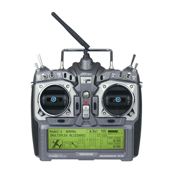
- Page 31 9 CHANNEL 2.4GHz AIRCRAFT COMPUTER RADIO SYSTEM The First Screen When you first turn on the Aurora 9X, the following screen will appear and you can find the information below. In AFHSS mode (with Maxima RX) : 1. The upper line has the number and name of the active model on the left.
- Page 32 9 CHANNEL 2.4GHz AIRCRAFT COMPUTER RADIO SYSTEM Multi I/O Screen Menu DataTran Radio A Radio B T.Pupil Note...
- Page 33 9. Receiver Battery Power Indicator 10. Active or Inactive Transmit Icon Touch Screen Lock function is not activated if Aurora 9X is not transmitting the frequency. When you find out Touch Screen Lock function is not working, please set frequency transmit on.
- Page 34 9 CHANNEL 2.4GHz AIRCRAFT COMPUTER RADIO SYSTEM Quick Start Guide to Set up a Simple Powered Airplane or Glider If you are setting up a powered or un-powered glider, we will be programming your plane into the ACRO menu for our demonstration.
- Page 35 9 CHANNEL 2.4GHz AIRCRAFT COMPUTER RADIO SYSTEM System Programming Menu 5. At the model selection screen press, New. We are programming a new model into the model memory slot number two, not the model memory slot one. For the purpose of this exercise it will ensure a fresh model memory with no existing programming. Note 6.
- Page 36 9 CHANNEL 2.4GHz AIRCRAFT COMPUTER RADIO SYSTEM System Programming Menu 11. Here is the screen that will tell the transmitter what kind of wing your plane has. There is a icon in the upper right of the screen. This means there are two pages in this menu. Touch the icon and note the second screen has even more wing type selections.
- Page 37 9 CHANNEL 2.4GHz AIRCRAFT COMPUTER RADIO SYSTEM System Programming Menu 16. The Aurora 9X’s channel can be changed easily. If you want to change the channel, select the “No” icon. If there’s no changes, select the“Yes” icon then it will go to the main screen.
- Page 38 Throttle Lock The Aurora 9X features a "throttle lock" function that can be activated when the transmitter is transmitting a signal. We encourage you to apply the throttle lock as a safety precaution against "accidental throttle application".
- Page 39 Using the following functions is not mandatory. For the purpose of our quick set-up guide tutorial they will explain most of the fundamental programming techniques available in the Aurora 9X. We highly suggest you follow along with program- ming the EPA, dual and exponential rate functions. Doing so will teach you valuable lessons and the basics you need to Note get the most out of your Aurora 9X.
- Page 40 7. Select D/R&EXP from the model menu 8. At the intermediary switch screen press the icon. 9. This is a map of the Aurora 9X switch layout. You can put the aileron dual rate function on any of the switches shown.
- Page 41 9 CHANNEL 2.4GHz AIRCRAFT COMPUTER RADIO SYSTEM Model Programming Menu 10. Now we are back to the D/R&EXP screen. 11. Follow steps 7 - 9 to program a 75% value for the elevator dual rate. Select the elevator dual rate to be active by assigning it on the same switch, “A”...
- Page 42 9 CHANNEL 2.4GHz AIRCRAFT COMPUTER RADIO SYSTEM Quick Start Guide to Setting Up a Simple Heli Channel assignments are: System Programming Menu 1. Turn on the transmitter; do not turn on the Heli. For safety reasons during this set-up exercise on an electric powered heli please remove the blades and/or un-plug the motor from the speed control.
- Page 43 9 CHANNEL 2.4GHz AIRCRAFT COMPUTER RADIO SYSTEM System Programming Menu We are programming a new model into the #2 model memory slot, not the model memory one slot. For the purpose of this exercise it will ensure a fresh model memory with no existing programming. Note 6.
- Page 44 9 CHANNEL 2.4GHz AIRCRAFT COMPUTER RADIO SYSTEM System Programming Menu There is a1/2 icon in the upper right of the screen. This means there are two pages in this menu. Touch the1/2 icon and note the second screen has even more swash type selections. Many function menus will have more than one screen of options.
- Page 45 Throttle Lock The Aurora 9X features a "throttle lock" function that can be activated when the transmitter is transmitting a signal. We encourage you to apply the throttle lock as a safety precaution against "accidental throttle application". 2. At the home page, let’s select some model...
- Page 46 9 CHANNEL 2.4GHz AIRCRAFT COMPUTER RADIO SYSTEM Model Programming Menu Sure there are many more functions you may wish to try, but for our example please follow along and do the ones we suggest for your first model set-up. Note 4.
- Page 47 9 CHANNEL 2.4GHz AIRCRAFT COMPUTER RADIO SYSTEM Model Programming Menu When making the following fundamental adjustments, the blades should be on the heli, and a pitch adjustment device showing the degrees of blade pitch should be used to set the collective end points correctly according to the heli manufacturer’s specs.
- Page 48 Using Exponential Rates 10. At the intermediary switch screen press the SEL. icon. 11. This is a map of the Aurora 9X switch layout. You can put the AILE expo select switch on any of the switches shown. then press Exit icon.
- Page 49 9 CHANNEL 2.4GHz AIRCRAFT COMPUTER RADIO SYSTEM Model Programming Menu 12. Back at the D/R&EXP screen For more advanced users, different expo and D/R values can be applied under different flight conditions. Note...
- Page 50 9 CHANNEL 2.4GHz AIRCRAFT COMPUTER RADIO SYSTEM System Menu If you have not already programmed a model with the preceding quick start guide, we encourage you to do so before tackling the System and Model programming sections of the manual. Model Select menu MDL Type Timer...
- Page 51 9 CHANNEL 2.4GHz AIRCRAFT COMPUTER RADIO SYSTEM System Menu Depending on the signal modulation being used, the home screen will have slightly different functions. Note Model Select Menu From the MDL Sel. menu you can: 1. Create a new model 2.
- Page 52 9 CHANNEL 2.4GHz AIRCRAFT COMPUTER RADIO SYSTEM Model Select Menu 3. Copy one model’s data into a new model memory slot 4. Reset the active model memory slot to factory default settings You can’t delete the active model. Note 5. Rename a model...
- Page 53 The model type screen defines the features of the active model. These are the features we told the radio our model had during the “create a new model” process plus all the default features. Here we define all the choices you have while setting up your aircraft in the Aurora 9X. Model Type ACRO...
- Page 54 9 CHANNEL 2.4GHz AIRCRAFT COMPUTER RADIO SYSTEM Model Type Menu If you select, Yes to the retract question, “Gear” will be associated with a channel shown in the channel function menu. You will have to associate a control or switch to the “Gear” function. Note This is the end of the acro model type menu.
- Page 55 9 CHANNEL 2.4GHz AIRCRAFT COMPUTER RADIO SYSTEM Model Type Menu Model Type GLID Menu Programming...
- Page 56 9 CHANNEL 2.4GHz AIRCRAFT COMPUTER RADIO SYSTEM Model Type Menu Model Type HELI Menu Programming...
- Page 57 9 CHANNEL 2.4GHz AIRCRAFT COMPUTER RADIO SYSTEM Model Type Menu...
- Page 58 9 CHANNEL 2.4GHz AIRCRAFT COMPUTER RADIO SYSTEM Timer Menu The AURORA 9X has three timers and one counter. Also, it supports two built-in timers which display total time and flight time. Timer 1 and Timer 2 Set-up...
- Page 59 9 CHANNEL 2.4GHz AIRCRAFT COMPUTER RADIO SYSTEM Timer Menu Flight Counter Flight counter is a function that can count the number of flights.
- Page 60 9 CHANNEL 2.4GHz AIRCRAFT COMPUTER RADIO SYSTEM Timer Menu We now have selected the throttle to activate the #2 timer when the throttle is “up”. When the throttle is back at idle, the timer is not running. The Integral Timer To reset the integral timer back to 00:00:00...
- Page 61 This menu has two screens. Note the icon, press it to see screen two. Note This level of choice defines the Aurora 9X's “open” software architecture. Experiment to find what you can do here, as there is no “right” or “wrong” way to do it.
- Page 62 9 CHANNEL 2.4GHz AIRCRAFT COMPUTER RADIO SYSTEM Trimstep At the Trim Step screen we can change the size of each step the digital trims move with one “beep”, or “movement step value” of a digital switch. a. Press the TrimStep icon from the system menu.
- Page 63 Press the Exit icon. HTS-SS Advance sensor station and the Aurora 9X The Aurora 9X transmitter is designed to show a variety of information in real time on the screen of the transmitter when connected to the HTS-SS Advance sensor station accessory.
- Page 64 9 CHANNEL 2.4GHz AIRCRAFT COMPUTER RADIO SYSTEM Sensor Menu a. Once the HTS-SS advance is connected to the Aurora 9X properly, select “Sensor” from the system b. You can change the settings for each sensor. mode which can see a variety data.
- Page 65 The Aurora9X can be used to help teach students how to fly with a variety of different features defined in the following section. Among the trainer features will be: The Aurora 9X is compatible with all other Hitec transmitter products using the 3.2mm stereo plug or the DINN connector plug. When using the transmitter in the trainer mode: Check this all before take-off.
- Page 66 Press the icon, toggle the H switch on and off to activate the student transmitter or return control to the master Aurora 9X. l. Press the Exit and return to the trainer menu screen. m. Next, press the...
- Page 67 9 CHANNEL 2.4GHz AIRCRAFT COMPUTER RADIO SYSTEM Spectra Control Menu Selecting the receiver type. a. Select Spectra from the system menu. b. Select the arrow icon to change the type of the receiver. c. After changing to Maxima, press the “SEL” icon. d.
- Page 68 9 CHANNEL 2.4GHz AIRCRAFT COMPUTER RADIO SYSTEM System Management Menu The System Management menu allows you to choose; a. From the system menu, select System Management. the backlight, the backlight time can be set. of the touch-lock, the touch-lock time can be set.
- Page 69 Change to a Li-Po battery, the Li-Po Option The nominal voltage of a two cell Li-Po or Lithium Polymer battery pack is 7.4V. The user has the option to power the Aurora 9X with a 2S formatted Li-Po but accepts full responsibility to do so safely. To use a Li-Po transmitter battery safely, you must remove the battery from the transmitter case for charging, and reinstall it after charging.
- Page 70 The mode or “stick” mode menu lets you easily select what mode you wish to use. The Aurora 9X supports Mode 1, 2, 3, 4 and two custom modes. In America, stick mode 2 is the most popular with at least 95% preferring it. Followed by stick mode 1 users and a fractional number preferring modes 3 and 4.
- Page 71 9 CHANNEL 2.4GHz AIRCRAFT COMPUTER RADIO SYSTEM Hardware Reverse Menu The Aurora 9x hardware reverse feature is the ability to invert the signal of the operation of the stick, switch, etc. a. Click the hardware reverse in system menu. b. Select which gimbal to reverse.
- Page 72 9 CHANNEL 2.4GHz AIRCRAFT COMPUTER RADIO SYSTEM Information Menu The transmitter info screen contains the following information about the Aurora 9X. To add your name to the Aurora 9X a. From the system menu, select b. Press the Rename icon.
- Page 73 9 CHANNEL 2.4GHz AIRCRAFT COMPUTER RADIO SYSTEM Information Menu f. Press the “Password” icon. g. Enter your password and press Enter. h. Check password once again and press Enter. i. Press Exit to back out to the system menu.
- Page 74 Reset just are not working the way they should, start over. There are thirty model memories in the Aurora 9X. Start a new model or Reset the current one in the System-MDL Sel. menu. You will lose all the programming you have done for that model up to that point, but starting over is the best “cure”...
- Page 75 Adjustment Menu Many of the Aurora 9X's features offer a switch selection process. One of the options presented in several of these features is to choose an “adjustment” switch. Most often this is VR switch LT, CT, RT or a slider, LS or RS.
- Page 76 2. Two and three position switch selection There are both two and three position switches on the Aurora 9X. They are used to do two things, turn a function on and off or, each switch position can be a travel rate value on multiple rate value functions.
- Page 77 9 CHANNEL 2.4GHz AIRCRAFT COMPUTER RADIO SYSTEM Selecting a Switch Two position on and off We will use the aileron to rudder mix to set up a two position switch on or off function. a. Select the icon from the model menu. b.
- Page 78 9 CHANNEL 2.4GHz AIRCRAFT COMPUTER RADIO SYSTEM Selecting a Switch Three position switch multiple value set-up For this example we will set three aileron movement value rates on a three position switch. Follow this method to set multiple values on any two position switch. Note a.
- Page 79 9 CHANNEL 2.4GHz AIRCRAFT COMPUTER RADIO SYSTEM Selecting a Switch g. Press the icon to get a 125% value for both the left and right aileron. h. Move switch C to the or (all the way towards you) position, bypassing the middle position.
- Page 80 9 CHANNEL 2.4GHz AIRCRAFT COMPUTER RADIO SYSTEM Adjust Function switch set-up c. Press the Adjust Function icon. d. Select SET. e. Press SEL. f. Let’s choose the switch to adjust the aileron to rudder mix. g. Press the Exit icon to go back to the adjustment range the LT switch is capable of, press the + RST-...
- Page 81 9 CHANNEL 2.4GHz AIRCRAFT COMPUTER RADIO SYSTEM Additional camber and launch mode adjust function menu (GLID) This is the Launch mix screen. Helicopter throttle and pitch curve adjust functions, hover trim and more and pitch trim. The pitch curve also includes a high pitch adjust, and a low pitch adjust switch option. In throttle curve adjust function menu you can choose: In the pitch curve adjust function menu you can choose: improve the performance of your heli without the expense of hardware upgrades.
- Page 82 Modern computer radios use a digital trim system. The Aurora 9X features four trim controls for the throttle and the three main axis of There are occasions when you may want to link the trim of one control to another control. The Aurora 9X offers two different trim link features;...
- Page 83 9 CHANNEL 2.4GHz AIRCRAFT COMPUTER RADIO SYSTEM Trim Link Activation T.APP primarily a feature of critical mixing functions. Again we use the aileron to rudder mix as an example. The default is to have the trims separate. To activate a trim link between aileron and rudder, so that adjusting the aileron trim will also adjust the rudder trim: a.
- Page 84 9 CHANNEL 2.4GHz AIRCRAFT COMPUTER RADIO SYSTEM Launch Cut switch set-up The launch mode features the option to have the cut control be applied to a stick movement. The launch function must have a switch assigned to it for the cut function to work. Note a.
- Page 85 9 CHANNEL 2.4GHz AIRCRAFT COMPUTER RADIO SYSTEM Model Menu and More - Menu Functions Common to all ACRO, GLID and HELI models. The following features are common to the ACRO, GLID and Heli model programs. Depending on the active model features as you defined them during the model set-up process, these functions may or may not be in the model menu.
- Page 86 9 CHANNEL 2.4GHz AIRCRAFT COMPUTER RADIO SYSTEM D/R & EXP (Dual Rates and Exponential Rates) This menu contains three valuable features. We will first discuss and show a dual rate set-up, then discuss and demonstrate exponential, or “expo”. The OST (Offset) feature can be applied to any channels “movement graph” as required.
- Page 87 9 CHANNEL 2.4GHz AIRCRAFT COMPUTER RADIO SYSTEM Sub-Trim (Servo Sub-Trim Adjustment) Your servo control arms should be as close to 90 degrees as possible, and the control surfaces as close to level as you can make them by adjusting the control linkages. Use the sub-trim feature to make very small adjustments to “center” the control surface.
- Page 88 9 CHANNEL 2.4GHz AIRCRAFT COMPUTER RADIO SYSTEM S. Speed (Servo Speed Adjustmemt) The servo speed menu will allow the manipulation of the servo speed through its travel. Servo speed can also be modified in several other menus using the ACC (acceleration) feature and the Speed option. ### This function can be influenced by the flight condition feature ### Note a.
- Page 89 9 CHANNEL 2.4GHz AIRCRAFT COMPUTER RADIO SYSTEM T.Limit (Travel Limit) This function is to set the maximum End Point of the servo. a. Select T.Limit in model menu. b. Select the servo channel that you want to set up. c. Locate the Trim in L position by moving the aileron stick all the way to left.
- Page 90 P. Mixes (Programmable Mix Menu) The Aurora 9X is capable of eight P. Mixes. Due to the number of ways the nine channels can be mixed, we want to illustrate an example of P Mix or “programmable mixing”. For this example we will mix throttle to rudder. The goal is to apply a small amount of rudder as the throttle is advanced to counteract the P-factor.
- Page 91 9 CHANNEL 2.4GHz AIRCRAFT COMPUTER RADIO SYSTEM P. Mixs (Programmable Mix Menu) if the throttle is moved the rudder will move. We must add the amount or “rate” value we want the rudder to move. Move the throttle stick up and down, the H and L values will alternately be highlighted and the throttle line will cross the graph.
- Page 92 It is often desirable to use a gyro on one or more flight control surfaces of both fixed wing aircraft and the on the tail rotor of helicopters. The Aurora 9X features up to three gyro sensitivity and switch control options per model memory, GY-1, GY-2 and GY-3.
- Page 93 9 CHANNEL 2.4GHz AIRCRAFT COMPUTER RADIO SYSTEM Gyro (on/off and Sensitivity Adjustment) j. Press to activate the gyro sensitivity menu. Switch Option k. Here we can choose a two or three position switch to apply different sensitivity values. Switch type Function 2 or 3 position Multiple values...
- Page 94 Flight Conditions The Flight Condition feature is clearly the most sophisticated and flexible of all the Aurora 9X functions. There are 7 flight conditions, condition 2 through 8. This is in addition to the NORMAL condition for a total of 8 different flight conditions you can program for the active model’s memory.
- Page 95 The flight condition tutorial To show you how to set-up, and use the Aurora 9X flight condition feature, follow along with this tutorial. You can change the switch location and other options when you choose to do this on your own later.
- Page 96 9 CHANNEL 2.4GHz AIRCRAFT COMPUTER RADIO SYSTEM FLT.COND (ACRO) l. Now we set-up “condition 3” the same way. Press INSERT m. Press Cond-3 n. Press o. Select NULL p. Press q. Press the icon for the 3 position switch C r.
- Page 97 9 CHANNEL 2.4GHz AIRCRAFT COMPUTER RADIO SYSTEM FLT.COND (ACRO) To set up by Switch Set up the Flight condition On/Off on elevator by Stick. a. Select b. Select STIC icon c. Select ELEV icon d. Select the Exit to return to the flight condition switch menu.
- Page 98 FLT.COND (GLID) The Aurora 9X offers a specific flight condition menu for glider functions. While all 8 conditions are available, we have named the first 5 for the most common conditional glider functions. The following shows the switch assignments of these 5 common conditions. Please review the next sections on how to manipulate these functions.
- Page 99 9 CHANNEL 2.4GHz AIRCRAFT COMPUTER RADIO SYSTEM FLT.COND (ACRO and GLID) At this point we can choose to modify the existing flight conditions we made. 1. Change the settings and copying existing flight condition 2. Delete any of the flight conditions you made 3.
- Page 100 C and S, Combination and Separate “movement value” set-ups. This is a huge feature. Take the time to understand it, as using the C and S option will expand the Aurora 9X’s capability in a dramatic way. When you have several different flight modes set-up, as you program control surface movement values into any of the following features, you can choose to have those values be associated with the C or S icon.
- Page 101 9 CHANNEL 2.4GHz AIRCRAFT COMPUTER RADIO SYSTEM Spoiler (GLID) Spoiler Function and Landing Mode. The Spoiler function will be used for a switch to deploy a spoiler flight surface. a slider control, use the spoiler to Elevator function on page 92. deployment feature will not work.
- Page 102 9 CHANNEL 2.4GHz AIRCRAFT COMPUTER RADIO SYSTEM SPO-ELE (GLID) Spoiler to Elevator Mix. Spoiler to elevator mix is used to progressively deploy a Spoiler and/or a landing configuration. The elevator compen- sation will counter the pitching of the aircraft when an airbrake is deployed. The default is the spoiler on the RS(right slider) control.
- Page 103 Press to access the menu screen. k. The Aurora 9X offers a 7 point curve on many of our adjustable mix menu items. To adjust the travel values, move the corresponding control stick or slider to align the moving line with the point you wish to adjust.
- Page 104 On or Off Yes, T.APP Fine tuning control choice d. The Aurora 9X offers a 7 point curve on many of our adjustable mix menu items. To adjust the travel values, move the corresponding control stick or slider to align the moving line with the point you wish to adjust.
- Page 105 As in many of the Aurora 9X’s model menu options, there are several airframe variables that are selected and appear in the different menu screens. In the case of the elevator to camber mix, the number of flaps and ailerons will appear as a variable based on the airframe type you told the radio you had at the time of initial model set-up in the system menu.
- Page 106 9 CHANNEL 2.4GHz AIRCRAFT COMPUTER RADIO SYSTEM RUD-AIL (ACRO and GLID) Rudder to Aileron Mix. If you wish to mix aileron into a rudder input, follow the directions below. ### This function can be influenced by the flight condition feature ### a.
- Page 107 9 CHANNEL 2.4GHz AIRCRAFT COMPUTER RADIO SYSTEM AIL DIFF (ACRO and GLID) Aileron Differential. Aileron differential is generally used to provide more up aileron, than down aileron travel. This will help prevent adverse yaw conditions when banking and rolling the aircraft. ### This function can be influenced by the flight condition feature ### a.
- Page 108 On or off Yes, T.APP Fine tuning control choice d. The Aurora 9X offers a 7 point curve on many of our adjustable mix menu items. To adjust the travel values, move the corresponding control stick or slider to align the moving line with the point you wish to adjust.
- Page 109 2 position On or Off Fine tuning control choice e. The Aurora 9X offers a 7 point curve on many of our adjustable mix menu items. To adjust the travel values, move the corresponding control stick or slider to align the moving line with the point you wish to adjust.
- Page 110 2 or 3 position On or off Fine tuning control choice d. The Aurora 9X offers a 7 point curve on many of our adjustable mix menu items. To adjust the travel values, move the corresponding control stick or slider to align the moving line with the point you wish to adjust.
- Page 111 9 CHANNEL 2.4GHz AIRCRAFT COMPUTER RADIO SYSTEM FLAPTRIM (ACRO) Flap Trim Mix. Typically, the function of flap trim is used to fine tune the up/down the two flaps. a. Select the Flap Trim icon from the model menu. b. Press to activate the Flap trim menu.
- Page 112 9 CHANNEL 2.4GHz AIRCRAFT COMPUTER RADIO SYSTEM V.Tail (ACRO and GLID) V.Tail Set up Aircraft with a V tail can use this function to limit the travel of the tail control servos up, down or both directions. It is not necessary to access or change this menu to fly a V tail aircraft. The default values are 100% movement in all directions.
- Page 113 9 CHANNEL 2.4GHz AIRCRAFT COMPUTER RADIO SYSTEM AILEVATOR (ACRO and GLID) Split Elevator and Aileron Mix Controls. The ailevator feature allows the adjustment of a two servo or split elevator. It also features an “aileron to split elevator” mix so when ailerons are applied, the elevators move in opposite directions. This is useful for advanced “taileron” aircraft, notably jets.
- Page 114 Elevon (ACRO and GLID) Flying Wing Mix. Flying wing aircraft will most often be set up using elevons. The Aurora 9X mixes the aileron and elevator functions to provide these controls in just one flight control surface per wing panel.
- Page 115 Throttle Cut Position. Many would agree a throttle cut function is required to safely fly glow and gas aircraft. The Aurora 9X’s throttle cut feature will bring the throttle servo to a programmed position allowing the motor to drop to low idle or to kill the power entirely.
- Page 116 There are many options for the throttle curve feature. It can be one of the most complicated features of the Aurora 9X. You can choose to use many or as few of the functions on this menu as you wish too.
-
Page 117: Idle Adjustment
9 CHANNEL 2.4GHz AIRCRAFT COMPUTER RADIO SYSTEM Idle Down (ACRO ) Idle Adjustment. The Idle Down function will apply a rate value to the throttle channel raising or lowering the throttle to a position determined by the user when a switch is activated. This position will become the low throttle point for as long as the switch is selected. - Page 118 9 CHANNEL 2.4GHz AIRCRAFT COMPUTER RADIO SYSTEM B-fly (GLID) Butterfly or Crow Mix. Butterfly, also known as “Crow” mixing is used to land slippery gliders easier and with greater accuracy. The mix is usually activated with the linear action of the throttle stick which drops the flaps, raises the ailerons and employs a bit of up elevator to compensate for the pitch down created by all the additional control surface drag.
- Page 119 NULL and follow the switch activation process. Normally throughout the Aurora 9X manual we don’t recommend a switch location. However, to trigger the snap roll feature we believe the “dead man” switch is the most practical location for the snap roll master switch function.
- Page 120 NULL and follow the switch activation process. Normally throughout the Aurora 9X manual we don’t recommend a switch location. However, to trigger the snap roll feature we believe the “dead man” switch is the most practical location for the snap roll master switch function.
- Page 121 9 CHANNEL 2.4GHz AIRCRAFT COMPUTER RADIO SYSTEM SnapRoll (ACRO) e. Choose a snap “type” for right inside, for left inside, for right outside and for left outside. f. Select a switch for the snap type you selected. Note the switch you selected appears on the direction part of the screen associated with the snap type you wanted.
- Page 122 9 CHANNEL 2.4GHz AIRCRAFT COMPUTER RADIO SYSTEM Knife Edge Mix(ARCO) Knife Edge Mix This mixing is helpful function on flight when operating Knife function more easily. ### This function can be influenced by the flight condition feature ### a. Select Knife Edge Mix from the model menu. b.
- Page 123 9 CHANNEL 2.4GHz AIRCRAFT COMPUTER RADIO SYSTEM Motor (GLID) Motor Control Menu. Use the motor function available in the GLID programming to turn an electric motor on or off using a two position switch. ### This function can be influenced by the flight condition feature ### a.
- Page 124 Check the On/Off by SW C set as initial value in the glider g. Select the Exit icon and return to the model menu The “Cut” function for the launch mode is different than any other cut function in the Aurora 9X.
- Page 125 9 CHANNEL 2.4GHz AIRCRAFT COMPUTER RADIO SYSTEM Offset (GLID) Offset Menu. This Offset is a function to fine-tune the aileron, elevator, and flap when using Glider. ### This function can be influenced by the flight condition feature ### a. Select Offset from the model menu. b.
- Page 126 4. Section five, common features of all model types After setting the heli up in the Aurora 9X system menu through the MDL. Sel. feature as described in section two, visit section five for all the basic set-up functions, then skip back to this section for the rest of the information.
- Page 127 Reset, the best hint of all As you program a model into any computer radio, especially one as sophisticated as the Aurora 9X, it is easy to make a mistake. If “things” just are not working the way they should, start over. There are thirty model memories in the Aurora 9X. Start a new model or Reset the current one in the System-MDL Sel.
- Page 128 Governor Aurora 9X sets 1/2 Idle up Hold by default. Once you are familiar with settings for the Aurora 9X, choose your preferred switch options. This is an additional condition for Normal condition when idle up is 1/2. It is set to hold when switch E is located at the bottom in normal condition and idle up 1 is pulling up to the top and idle up 2 and switch G are pulling in middle step.
- Page 129 9 CHANNEL 2.4GHz AIRCRAFT COMPUTER RADIO SYSTEM FLT.COND (HELI) c. Idle-up 2 has been set by default as follows: d. Hold has been set by default as follows e. Click to the Exit icon to return to model menu. At this point we can choose to modify the existing flight conditions we made: 1.
- Page 130 P. Curve and T. Curve In the Aurora 9X, both the pitch AND throttle curve functions are on the same menu, IF both pitch and throttle curve functions are “active”. Additionally both menus are defined the same way, so to avoid repetition we will explain both throttle and pitch curve menus here.
- Page 131 9 CHANNEL 2.4GHz AIRCRAFT COMPUTER RADIO SYSTEM Pitch and Throttle Curves (HELI) f. Note the THRO arrow NORMAL line on the menu. Pressing the arrow will cycle you to the Throttle Curve menu. Switch Option and in flight Fine Trim Adjustment Switch Function. g.
- Page 132 9 CHANNEL 2.4GHz AIRCRAFT COMPUTER RADIO SYSTEM Needle (HELI) Carburetor Mixture Adjustment. The Needle function is really two features: one is a manual needle adjustment independent of a mix. This is done by moving the LS slider control. The goal is to lean or richen the fuel mixture in relation to the blade pitch values. The second is a switched, automatic mix between a mixture control servo of a glow or gas heli motor, and the blade pitch.
- Page 133 9 CHANNEL 2.4GHz AIRCRAFT COMPUTER RADIO SYSTEM SWH-THR (HELI) Swash to Throttle Mix. A swash to throttle mix is typically used to increase the throttle RPM when a swash input is given to the heli. The increased RPM compensates for loss of rotor disk lift as a result of the rotor disk tilt. ### This function can be influenced by the flight condition feature ### a.
- Page 134 9 CHANNEL 2.4GHz AIRCRAFT COMPUTER RADIO SYSTEM RUD-THR (HELI) Tail Rotor to Throttle Mix. This mix is between the rudder, or tail rotor input and the throttle. It is generally used to raise or lower the throttle RPM slightly to compensate for tail rotor dynamics. ### This function can be influenced by the flight condition feature ### a.
- Page 135 9 CHANNEL 2.4GHz AIRCRAFT COMPUTER RADIO SYSTEM T. HOLD (HELI) Throttle Hold Position Throttle hold is used to set the throttle at a programmed position when throttle hold is selected. This Function is often used to faciliate auto rotation maneuvers. ### This function can be influenced by the flight condition feature ### To use the Auroras throttle hold feature;...
- Page 136 9 CHANNEL 2.4GHz AIRCRAFT COMPUTER RADIO SYSTEM Swash Mix (HELI) Swash Plate Adjustment Menu. Use the swash mix feature to apply a fine adjustment to the swash plate travel. For the very best accuracy, we recommend the use of a swash plate leveling set-up tool. As this is a set-up feature, swash mix is one of the few functions that is NOT influenced by flight conditions, idle-up or hold conditions.
- Page 137 9 CHANNEL 2.4GHz AIRCRAFT COMPUTER RADIO SYSTEM Calibration menu The use of a swash leveling tool is mandatory for the super fine adjustment provided in this menu. . Select the Calibration icon. i. From this intermediate menu, select the function to adjust. For our example select Pitch.
- Page 138 9 CHANNEL 2.4GHz AIRCRAFT COMPUTER RADIO SYSTEM Swash Mix (HELI) Switch Option o. To select a 2 or 3 position switch that will allow multiple mix values, press NULL and follow the switch activation process. Switch type Function 2 or 3 position Multiple values p.
- Page 139 9 CHANNEL 2.4GHz AIRCRAFT COMPUTER RADIO SYSTEM REVO Mix (HELI) Revolution Mix. Revo, or revolution mixing is used to dampen the torque created by the main rotor speed and pitch variations during flight. Revo mix is not used when a modern heading hold gyro is installed in the heli. The heading hold function of the gyro will correct the issue.
- Page 140 Gyro on/off and Sensitivity Adjustment. Almost all modern helicopters use a gyro on the tail rotor control. The Aurora 9X offers you the ability to use a switch to have three different gyro “rates” per flight condition or “idle-up” and hold condition.
- Page 141 Governor (HELI) RPM Governor Device Menu. The Aurora 9X features up to three Governor and switch control rate values per model memory. ### This function can be influenced by the flight condition feature ### To effectively set up the governor function, you should have the governor manufacturer’s instruction manual available to you.
- Page 142 9 CHANNEL 2.4GHz AIRCRAFT COMPUTER RADIO SYSTEM Governor (HELI) % Unit of Value operation b. The default sensitivity value is 50% (1500RPM) and the Maxium value is 110%(2100 RPM). According to the governor manufacturer's guidelines, apply an appropriate % value with the + RST –...
- Page 143 9 CHANNEL 2.4GHz AIRCRAFT COMPUTER RADIO SYSTEM...
Need help?
Do you have a question about the Aurora 9X and is the answer not in the manual?
Questions and answers