Table of Contents
Advertisement
Quick Links
Advertisement
Table of Contents

Related Manuals for HITEC Flash8


Summary of Contents for HITEC Flash8
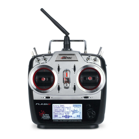
- Page 1 8 Channel 2.4 GHz Aircraft Computer Radio System...
-
Page 2: Table Of Contents
Important Notices Safety Information........................7 Please note that Hitec reserves the right to make production changes during the life of our product lines Product Support..........................8 that may impact the information in this manual. For the most up-to-date information on this and any Steps for Successfully Programming the Flash 8 Radio...........9... - Page 3 8 Channel 2.4 GHz Aircraft Computer Radio System 8 Channel 2.4 GHz Aircraft Computer Radio System Table of Contents Table of Contents Common Model Programming Menu Helicopter Programming Working with the Common Model Function Menus........45 Helicopter Programming Menu..............91 Servo Reverse....................46 Gyro........................91 Sub Trims......................46 Throttle Cut.......................94...
-
Page 4: Introduction
Introduction Safety Information Thank you for purchasing the Flash 8 radio by Hitec. Designed for all popular aircraft types, the Flash 8 Flying models can be dangerous if proper safety precautions are not followed. Here are a few critical delivers lightning fast response with its 7ms frame rate and 4096 step resolution. You can trust Hitec’s safety suggestions to keep you and others safe. -
Page 5: Product Support
7. Using the Flash 8’s Telemetry Capabilities. Hitec Web Site Make plans to visit the Hitec web site on a regular basis at www.hitecrcd.com. There you will find specs Warning, Caution, Note and Tip Boxes and other information about the entire Hitec product line, and soon our FAQ pages will hold valuable Throughout the manual, you will see important information inside a labeled box. -
Page 6: System Component Specifications
We recommend that you read the introductory information in section one, then proceed to one of the AFHSS 2.4GHz Signal: Hitec’s 2.4GHz R/C signal protocol. Adaptive Frequency Hopping Spread Spectrum. quick start guides and start programming. After following along with the quick start guide you will have a Telemetry: Data signal from the model, transmitted to the transmitter. -
Page 7: Warning
Right Gimbal J3/J4 J1/J2 The supplied Hitec LiFe battery has a built-in protection circuit. This circuit could be damaged if you attempted to perform a high current quick charge or discharge. The supplied battery should Left Gimbal Trims Right Gimbal Trims Warning only be charged with the supplied charger. -
Page 8: Main Menu
8 Channel 2.4 GHz Aircraft Computer Radio System 8 Channel 2.4 GHz Aircraft Computer Radio System Main Menu Maxima Series Receivers Model Name Battery Voltage Battery Capacity Remaining The Maxima series is designed for use with G2 AFHSS radios such as the Aurora 9X and Flash series. -
Page 9: Optima And Minima Receivers
(6L utilizes a soft case and exposed output block) exposed output block 1. Function Button: Used for binding the receiver to a module or Hitec 2.4 built-in transmitters, entering Press and hold the link button on the Receiver and turn on the power. - Page 10 Optima and Minima Series Receiver Link (ID-Setting or Bind) Compatibility: Your Hitec AFHSS system uses a communication protocol that links and binds the Hitec 2.4GHz receiver to The OPTIMA & MINIMA receivers are compatible with transmitters using the Hitec AFHSS 2.4 GHz system, your transmitter.
- Page 11 8 Channel 2.4 GHz Aircraft Computer Radio System 8 Channel 2.4 GHz Aircraft Computer Radio System Optima and Minima Series Receiver Link (ID-Setting or Bind) cont. FAIL-SAFE and Hold Mode Setup If the FAIL-SAFE function is set up and used properly but the receiver signal is somehow interrupted, the servos will move to your previously stored FAIL-SAFE setup.
-
Page 12: Telemetry System
30 meters, to test the effective range. The Hitec offers a wide variety of telemetry sensors designed to work with both fuel and electric powered model should exhibit no signs of signal loss during the range check. -
Page 13: Scan Mode Function
Firmware Updates in scan mode. Firmware updates can be loaded to the Flash 8 with a Hitec HPP-22 PC Interface module. The Flash 8 should be connected to the HPP-22 through the transmitter’s trainer port using the connector included with the interface module. Follow the HPP-22 manual to complete the firmware update. -
Page 14: Quick Start Guides
8 Channel 2.4 GHz Aircraft Computer Radio System 8 Channel 2.4 GHz Aircraft Computer Radio System Airplane Quick Start Guide Airplane Quick Start Guide cont. The following information is designed to guide you through a simple setup of a standard sport plane or We are programming a new model into the model memory slot number two, not the model unpowered glider. -
Page 15: Helicopter Quick Start Guide
8 Channel 2.4 GHz Aircraft Computer Radio System 8 Channel 2.4 GHz Aircraft Computer Radio System Airplane Quick Start Guide cont. Helicopter Quick Start Guide cont. 5. Select the first default model (NONAME-1) and press the jog If your receiver is not bound/linked to your transmitter you will need to follow the procedures dial to bring up the model maintenance prompts. -
Page 16: System Menu Programming
8 Channel 2.4 GHz Aircraft Computer Radio System 8 Channel 2.4 GHz Aircraft Computer Radio System System Menu Model Select Menu There are two primary menus in the Flash 8 programming structure: the System Function Menu, and Create a new model: When you create a new model you are the Model Function Menu. -
Page 17: Model Type Menu
8 Channel 2.4 GHz Aircraft Computer Radio System 8 Channel 2.4 GHz Aircraft Computer Radio System Model Select Menu cont. Model Select Menu cont. Reset the active model memory slot to factory default settings: Rename a model: a. In the model select menu, highlight the model you wish to a. -
Page 18: Model Type Acro Menu Programming
8 Channel 2.4 GHz Aircraft Computer Radio System 8 Channel 2.4 GHz Aircraft Computer Radio System Model Type ACRO Menu Programming Model Type ACRO Menu Programming cont. 1. From the System Menu select MDL TYPE. 6. Scroll to “TAIL” and press the jog dial to activate the menu. The choices for tail type are dependent on the type of wing you selected. -
Page 19: Model Type Heli Menu Programming
8 Channel 2.4 GHz Aircraft Computer Radio System 8 Channel 2.4 GHz Aircraft Computer Radio System Model Type GLID Menu Programming cont. Model Type HELI Menu Programming 4. In the GLID setup menu, you will set your wing and tail choices. 1. -
Page 20: Channel Selection Menu
Trainer the jog dial to activate the selection menu. The Flash 8 can be paired with another Hitec transmitter to create a master/slave setup that is useful 4. Scroll through the choices to select the desired function of when instructing student pilots. -
Page 21: Trainer Function
8 Channel 2.4 GHz Aircraft Computer Radio System 8 Channel 2.4 GHz Aircraft Computer Radio System Section 3: System Menu Programming Trainer cont. Trainer cont. Within the trainer menu, you can set the Flash 8 as a “Master radio”, set the trainer switch and activate 9. -
Page 22: Control Modes
8 Channel 2.4 GHz Aircraft Computer Radio System 8 Channel 2.4 GHz Aircraft Computer Radio System Control Modes Management Menu cont. The Flash 8 is capable of operating in control Modes 1 - 4. The default is “Mode 2” for radios sold in North 4. -
Page 23: Common Model Programming Menu
8 Channel 2.4 GHz Aircraft Computer Radio System 8 Channel 2.4 GHz Aircraft Computer Radio System Management Menu cont. Common Model Programming Menu 15. Scroll to highlight “FLIGHT CONDITION” and press the jog dial The Model Function menu contains options that relate to all model types (common) as well as options to activate the menu. -
Page 24: Servo Reverse
8 Channel 2.4 GHz Aircraft Computer Radio System 8 Channel 2.4 GHz Aircraft Computer Radio System Servo Reverse Dual Rates The Reverse screen allows you to specify the direction of servo rotation for channels 1-8 of the active The Dual Rate (D/R) feature provides a method to define two different values of servo movement (“rates”) model. -
Page 25: Exponentials
8 Channel 2.4 GHz Aircraft Computer Radio System 8 Channel 2.4 GHz Aircraft Computer Radio System Exponential Exponential cont. 9. Scroll to highlight the “EXP” field and press the jog dial to 16. Scroll to select the switch you have chosen to control dual activate the menu. -
Page 26: Servo Speed
8 Channel 2.4 GHz Aircraft Computer Radio System 8 Channel 2.4 GHz Aircraft Computer Radio System End Point Adjustments cont. Servo Speed cont. 5. Scroll to highlight the “L/U” (left/up) field and press the jog dial 3. Rotate the jog dial clockwise or counter-clockwise to alter the to activate the menu. - Page 27 8 Channel 2.4 GHz Aircraft Computer Radio System 8 Channel 2.4 GHz Aircraft Computer Radio System Programmable Mixes cont. Programmable Mixes cont. 6. Scroll to select the desired function to be the slave function 13. Scroll to highlight the “OST” (offset) field and press the jog for the mix and press the jog dial to confirm your selection.
-
Page 28: Timers
8 Channel 2.4 GHz Aircraft Computer Radio System 8 Channel 2.4 GHz Aircraft Computer Radio System Programmable Mixes cont. Timers 21. Press the jog dial again to enable selections in the S/W menu. The Flash 8 features two customizable timers that can be triggered by switches or the throttle position. Downward counting timers can be helpful in making sure that you land before running out of fuel or 22. -
Page 29: Servo Monitors
8 Channel 2.4 GHz Aircraft Computer Radio System 8 Channel 2.4 GHz Aircraft Computer Radio System Timers cont. Timers cont. 10. Scroll to highlight “MODE” and press the jog dial to activate the - Scroll to select “ON” and press the jog dial to confirm your menu. -
Page 30: Throttle Lock
8 Channel 2.4 GHz Aircraft Computer Radio System 8 Channel 2.4 GHz Aircraft Computer Radio System THRO Lock cont. Servo Monitors cont. 3. Scroll to select a switch used to activate the throttle lock function. Press the jog dial to confirm your selection. If you are configuring an electric-powered model, remove the propeller(s) or secure the aircraft before performing the next steps. -
Page 31: Acro And Glider Programming
8 Channel 2.4 GHz Aircraft Computer Radio System 8 Channel 2.4 GHz Aircraft Computer Radio System Acro and Glider Programming Menu Working with the Acro/Glid Model Function Menu When the active model is configured as fixed-wing (ACRO or GLID) model type, the Model Function menu contains programming options which are useful for fixed-wing aircraft. -
Page 32: Aileron Differentials
8 Channel 2.4 GHz Aircraft Computer Radio System 8 Channel 2.4 GHz Aircraft Computer Radio System Flight Conditions cont. Flight Conditions cont. 1. From the model menu, rotate the jog dial to highlight 5. Scroll to highlight the “SPEED” field and press the jog dial to “F.COND”... -
Page 33: Elevon Mixing
8 Channel 2.4 GHz Aircraft Computer Radio System 8 Channel 2.4 GHz Aircraft Computer Radio System Aileron Differentials cont. Elevon Mixing cont. 4. Scroll to the “S/W” field and press the jog dial to activate the 3. Scroll to highlight the “L/U” (left/up) field and press the jog dial to menu. -
Page 34: V-Tail Mixing
8 Channel 2.4 GHz Aircraft Computer Radio System 8 Channel 2.4 GHz Aircraft Computer Radio System Elevon Mixing cont. V-Tail Mixing cont. 15. If aileron or elevator functions operate in the incorrect 5. Scroll to highlight the “R/D” (right/down) field and press the jog direction, highlight the direction field (“nor”) under the function dial to activate the menu. -
Page 35: Ailevator Mixing
8 Channel 2.4 GHz Aircraft Computer Radio System 8 Channel 2.4 GHz Aircraft Computer Radio System V-Tail Mixing cont. Ailevator Mixing cont. 16. Scroll to select “rev” and press the jog dial to confirm your selection. Verify that the control surfaces now 7. -
Page 36: Aileron To Rudder Mixing
8 Channel 2.4 GHz Aircraft Computer Radio System 8 Channel 2.4 GHz Aircraft Computer Radio System Aileron to Rudder Mixing Aileron to Rudder Mixing cont. Many models (especially large-scale aircraft) fly through turns more smoothly when aileron and rudder 11. The “I/O” (input/output) field is display only. It shows the value of the aileron and rudder channels as commands are used simultaneously. -
Page 37: Elevator To Camber Mixing
8 Channel 2.4 GHz Aircraft Computer Radio System 8 Channel 2.4 GHz Aircraft Computer Radio System Aileron to Rudder Mixing cont. Elevator to Camber Mixing cont. 19. To set up aileron to rudder mixing in accordance with a Flight 4. Scroll to the function field (“AILE” or “FLAP”). If “AILE” is not Condition: the current function, press the jog dial to activate the menu. - Page 38 8 Channel 2.4 GHz Aircraft Computer Radio System 8 Channel 2.4 GHz Aircraft Computer Radio System Elevator to Camber Mixing cont. Elevator to Camber Mixing cont. 14. Scroll to highlight the “SPEED” field and press the jog dial to 24. To set-up Elevator to Camber mixing in accordance with a activate the menu.
- Page 39 8 Channel 2.4 GHz Aircraft Computer Radio System 8 Channel 2.4 GHz Aircraft Computer Radio System Camber Mix cont. Camber Mixing cont. 6. If the model has a second aileron servo, repeat step 5 in the 16. Scroll to select a switch to activate the camber mix. Press the jog dial to confirm your selection. “AIL2”...
-
Page 40: Flap Control
8 Channel 2.4 GHz Aircraft Computer Radio System 8 Channel 2.4 GHz Aircraft Computer Radio System Flap Control Flap Control cont. Flap Control is used to mix elevator control with flap movements. This is an effective way of avoiding pitch 11. -
Page 41: Landing Mix
8 Channel 2.4 GHz Aircraft Computer Radio System 8 Channel 2.4 GHz Aircraft Computer Radio System Flap Control cont. Landing cont. To disable flap control: 12. If a second flap set up for the aircraft is needed, repeat the 1. Scroll to highlight the “MIX” field in the flap control menu and steps 10 and 11 to change the “FLAP2”... -
Page 42: Butterfly Mixing (Glid Only)
8 Channel 2.4 GHz Aircraft Computer Radio System 8 Channel 2.4 GHz Aircraft Computer Radio System Landing cont. Butterfly Mixing (B. FLY GLID Only]\) cont. To disable the landing mix: 7. Scroll to highlight the “ELEV” field and press the jog dial to 1. -
Page 43: Gyro
8 Channel 2.4 GHz Aircraft Computer Radio System 8 Channel 2.4 GHz Aircraft Computer Radio System Butterfly Mixing (B. FLY GLID Only) cont. Butterfly Mixing (B. FLY GLID Only) cont. - Scroll to select “ON” and press the jog dial to confirm your If you are using multiple flight conditions, you must define butterfly values for each flight selection. -
Page 44: Throttle Cut (Acro Only)
8 Channel 2.4 GHz Aircraft Computer Radio System 8 Channel 2.4 GHz Aircraft Computer Radio System Throttle Cut (Acro Only) Gyro cont. 7. Scroll to highlight “S/W” and press the jog dial to activate the Throttle Cut is a vital safety feature when flying glow or gas-powered models. This feature will command switch menu. -
Page 45: Throttle Curve
8 Channel 2.4 GHz Aircraft Computer Radio System 8 Channel 2.4 GHz Aircraft Computer Radio System Throttle Cut (Acro Only) cont. Throttle Curve (Acro Only) cont. - Scroll to select “ON” and press the jog dial to confirm your 4. Scroll to the “1” field and press the jog button to activate the selection. -
Page 46: Helicopter Programming Menu
8 Channel 2.4 GHz Aircraft Computer Radio System 8 Channel 2.4 GHz Aircraft Computer Radio System Throttle Curve cont. Helicopter Programming Menu 15. Rotate the jog dial to select a switch to activate the throttle curve. Press the jog dial to confirm your When the active model is configured as a helicopter model type, the model function menu contains selection. - Page 47 8 Channel 2.4 GHz Aircraft Computer Radio System 8 Channel 2.4 GHz Aircraft Computer Radio System Gyro cont. Gyro cont. 1. From the Model menu, rotate the jog dial to highlight “GYRO” 6. Scroll to highlight “S/W” and press the jog dial to activate the and press the jog dial once to enter the activation menu.
-
Page 48: Throttle Cut
8 Channel 2.4 GHz Aircraft Computer Radio System 8 Channel 2.4 GHz Aircraft Computer Radio System Throttle Cut Throttle Cut cont. Throttle Cut is a vital safety feature when flying glow or gas-powered models. This feature will command 8. To disable Throttle Cut: the throttle servo to a preprogrammed position with a switch movement. -
Page 49: Revolution Mixing
8 Channel 2.4 GHz Aircraft Computer Radio System 8 Channel 2.4 GHz Aircraft Computer Radio System Revolution Mixing Revolution Mixing cont. The revolution mix is used to prevent yaw effects caused by changes in head speed or blade pitch on the 9. -
Page 50: Swash To Throttle Mixing
8 Channel 2.4 GHz Aircraft Computer Radio System 8 Channel 2.4 GHz Aircraft Computer Radio System Revolution Mixing cont. Swash to Throttle Mixing b. If you choose a switch: A swash to throttle mix is typically used to increase main rotor RPM when a swash control command is - The switch position menu will appear. - Page 51 8 Channel 2.4 GHz Aircraft Computer Radio System 8 Channel 2.4 GHz Aircraft Computer Radio System Swash to Throttle Mixing cont. Swash to Throttle Mixing cont. 11. Scroll to highlight the “OST” (Offset) field and press the jog 22. To set up the Swash to Throttle mixing in accordance with a dial to activate the menu.
-
Page 52: Throttle Curve
8 Channel 2.4 GHz Aircraft Computer Radio System 8 Channel 2.4 GHz Aircraft Computer Radio System Throttle Curve cont. Swash Mix cont. 6. Scroll to the “2” field and press the jog button to activate the 3. Rotate the jog dial clockwise or counter-clockwise to alter the menu. -
Page 53: Pitch Curve
8 Channel 2.4 GHz Aircraft Computer Radio System 8 Channel 2.4 GHz Aircraft Computer Radio System Throttle Curve cont. Pitch Curve The Pitch Curve function allows you to modify the normally-linear servo rate movement for collective Throttle Adjust Feature: Program the LS, RS, LT, or RT switches to work as in-flight adjustment pitch by defining five different points along the pitch response curve. -
Page 54: Flight Conditions
8 Channel 2.4 GHz Aircraft Computer Radio System 8 Channel 2.4 GHz Aircraft Computer Radio System Pitch Curve cont. Pitch Curve cont. 13. Scroll to highlight “S/W” and press the jog dial to bring up the 18. To set up Pitch Curve in accordance with a Flight Condition switch sub-menu. -
Page 55: Swash Ring
8 Channel 2.4 GHz Aircraft Computer Radio System 8 Channel 2.4 GHz Aircraft Computer Radio System Flight Conditions cont. Flight Conditions cont. 2. Scroll to the flight condition to be configured and press the 6. Rotate the jog dial to define the amount of time (0.0 to 10.0 jog dial to confirm your selection. -
Page 56: Throttle Lock
When paired with an Optima 7, Optima 9, or Optima SL receiver, the Flash 8 is fully compatible with a signal. We encourage you to use the throttle lock feature as a safety precaution against “accidental Hitec’s suite of telemetry sensors. The ability to receive important data from the model is critical to throttle application”. -
Page 57: Gps
8 Channel 2.4 GHz Aircraft Computer Radio System 8 Channel 2.4 GHz Aircraft Computer Radio System RPM cont. The GPS screen displays real-time latitude, longitude, altitude and speed data. 2. Scroll to the top “UNIT” field and press the jog dial to confirm Required Sensor: HTS-GPS GPS Sensor your selection. -
Page 58: Battery
Advanced the menu. The Advanced screen displays airspeed data collected from Hitec’s dedicated airspeed sensor (not GPS), as well as rate-of-climb data collected by a variometer. Required Sensor: HTS-AS Air Speed Sensor and HTS-VM Variometer Sensor (both sensors are compatible only with the HTS-SS Advanced Sensor Station) 3. -
Page 59: Viewing Telemetry Data
8 Channel 2.4 GHz Aircraft Computer Radio System 8 Channel 2.4 GHz Aircraft Computer Radio System Advanced cont. Stick Length Adjustment 5. Scroll to select “ON” if you would like the transmitter to emit a Hands come in all sizes so, to accommodate everyone, we use a two piece stick “top” that can be adjusted tone when the model is losing altitude.
Need help?
Do you have a question about the Flash8 and is the answer not in the manual?
Questions and answers