Yamaha MT100II Operation Manual
Yamaha mt100ii multitrack cassette recorder
Hide thumbs
Also See for MT100II:
- Operation manual (80 pages) ,
- Operation manual (80 pages) ,
- Operation manual (80 pages)
Table of Contents
Advertisement
Quick Links
Download this manual
See also:
Operating Manual
Advertisement
Table of Contents

Related Manuals for Yamaha MT100II


Summary of Contents for Yamaha MT100II
- Page 1 YAMAHA ® AUTHORIZED PRODUCT MANUAL MULTITRACK CASSETTE RECORDER...
- Page 2 YAMAHA MULTITRACK CASSETTE RECORDER OPERATION MANUAL...
-
Page 3: Table Of Contents
THE CONTROLS AND CONNECTORS ..... 2 MT100II CONTROLS AND THEIR FUNCTIONS ....2 CONNECTION EXAMPLES . -
Page 4: Precautions
Also avoid locations which are subject 7. ALWAYS USE THE CORRECT POWER SUPPLY to excessive dust accumulation or vibration which could The MT100II should only be powered using the supplied cause mechanical damage. YAMAHA PA100 AC Adaptor. The use of other adaptors can cause serious damage to the MT100II. -
Page 5: The Controls And Connectors
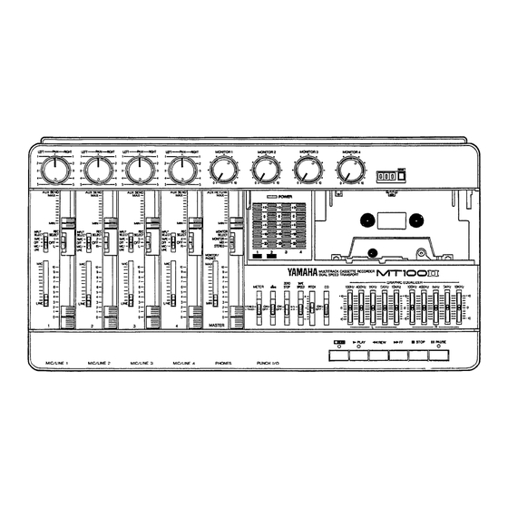
THE CONTROLS AND CONNECTORS MT100II MULTlTRACK CASSETTE RECORDER... -
Page 6: Mt100Ii Controls And Their Functions
MT100lI’s mixer section has four “channels.” The term “track” refers to the magnetic bands on tape used to store signals recorded by MT100II's recorder section. Since MT100II records four separate bands of audio on tape, it is a four-“track” recorder. - Page 7 The MASTER fader sets the overall output level of the effects such as reverberation or echo to the sound of a MT100II mixer section, and thus the level of the output channel or track. The AUX SEND control on each mixer signal appearing at the STEREO OUT jacks.
- Page 8 The TAPE SPEED switch selects either the standard 4.8- LED will flash when the REC button is pressed, and cm/sec cassette tape speed, or the MT100II's special 9.5- the orange PAUSE indicator will light. If any REC SE- cm/sec high tape speed. Use the standard (4.8) speed...
- Page 9 OUT jacks can also be used to feed each of the recorder’s tracks to external signal processors, the output of which [Note] Since the MT100II uses the entire width of the cas- can then be returned to the MT100lI’s mixer inputs.
- Page 10 Press the POWER switch once to turn power ON, a second time to turn power OFF. When the power is ON, the POWER LED above the LED peak meters on the MT100II top panel will light. Make sure that the input faders are set to “0”...
-
Page 11: Connection Examples
CONNECTION EXAMPLES —- BASIC CONNECTIONS —- Make sure the power to all equipment is OFF when making connections. Monitor Power Amp/Speaker 8 MT100Il MULTITRACK CASSETTE RECORDER... -
Page 12: About Cassette Tapes
ABOUT CASSETTE TAPES This unit is designed to be used only with Chromeposition tape, and will not work properly with Ferrichrome tape formulations. tape (Bias: HIGH; EQ: 70µs) should be used. Also, the use of C-120 tapes is not recommended because they exhibit poorer performance, and can be the cause of equipment failure. -
Page 13: The Recording Process
For details pertaining to the operation of MT100lI controls, please refer to page 3, “MT100II CONTROLS AND THEIR FUNCTIONS”. Recording with the MT100II is a very simple process. All you need is the MT100II, a pair of monitor headphones, and an instrument, microphone, or other signal source. -
Page 14: Recording The First Track
Depending on what you are recording, you might want to record a single instrument or other source on a single track of the tape, or you might want to combine several instruments or other sources and record them on a single track. The MT100II offers two “channel-to-track assignment”... -
Page 15: Step 2: Monitor Setup
The MT100II allows you to monitor the material being recorded either via a pair of headphones connected to the PHONES jack or via a sound system with speakers connected to the MONITOR OUT jacks. The level appearing at the PHONES jack and MONITOR OUT jacks is controlled by the MONITOR/PHONES control. -
Page 16: Step 3: Setting Recording Levels
This is to ensure the best possible signal-to-noise ratio and allow plenty of plus and 3. Press transport RECORD button, this activates MT100II’s minus leeway for later adjustment. If the fader setting is record circuit, and puts the transport in RECORD/PAUSE way off, try adjusting the volume control on the instrument mode. -
Page 17: Overdubbing
MONITOR select switch to the MIX position. 7. Make sure the tape is rewound to the beginning of the piece and start recording. These steps are simply repeated to overdub tracks 3 and 4. 14 MT100II MULTITRACK CASSETTE RECORDER... -
Page 18: Ping-Pong Recording
4-track recorder. While mixing the first 3 tracks down onto less you go back and record the original tracks all track 4 you can also mix in a live instrument via the MT100II over again. mixer section. That would give you 4 parts recorded on track 4 of the tape. -
Page 19: A Ping-Pong Recording Example
“L”, the output of the effect processor connected to the LEFT AUX RETURN jack will be recorded. If the RECORD SELECT switch is set to “R”, the output of the effect processor connected to the RIGHT AUX RETURN jack will be recorded. 16 MT100II MULTITRACK CASSETTE RECORDER... -
Page 20: Mixdown
Mixdown is the last stage in the recording process at which time you can blend and polish the sounds to create the final product. A ‘MIX” is created by finely balancing the four tracks to achieve just the right sound. This final balance is achieved using MT100II’s mixer section and is re-recorded onto a conventional stereo tape deck. -
Page 21: Using The Graphic Equalizer
USING THE GRAPHIC EQUALIZER The MT100II has a stereo 5-band graphic equalizer built in. As the block diagram below makes clear, signals assigned to the left Therefore, can be and right channels by the PAN control and level adjusted using the MASTER fader are sent to the equalizer. -
Page 22: Using The Tape Out Jacks
USlNG THE TAPE OUT JACKS The tape out jacks can be used to feed the tape outputs to an external mixer. In mixdown, individual tracks can be processed using a signal processor, which receives signal from the TAPE OUT jack and the output of which is returned to a channel’s INPUT jack. -
Page 23: Using The Aux Send/Return Loop
USlNG THE AUX SEND/RETURN LOOP The MT100II’s AUX SEND controls function like a secondary mixer that derives its input signals from the main mixer’s four channels and combines them into a mono signal which is delivered via the AUX SEND jack (refer to the diagram below). You can use the AUX SEND controls to create an “effect mix”, independent of the main mix, thus adding the required degree of effect to each channel... -
Page 24: Punch-In/Out Recording
Footswitch Punch-in/out Punch-in/out Using the REC SELECT Switches 1. Plug a YAMAHA FS-1 (optional) footswitch into the 1. With all REC SELECT switches set to OFF, start the re- MT100II PUNCH I/O jack. -
Page 25: Maintenance
MAINTENANCE The MT100II recording & playback head has been precision-constructed to extremely fine tolerances in order to make high-quality 4- track recording possible. Optimum performance can only be achieved if the head surface is kept immaculately clean. Cleaning should be carried out at regular intervals — at least after every 10 hours of use. -
Page 26: Specifications
SPECIFICATIONS TAPE TRANSPORT Chrome (70 microsec. EQ) Tape Type 4-channel Permalloy rec/play head Heads 4-channel ferrite erase head 4.8 cm/sec 9.5 cm/sec Tape Speed ± 10% Pitch Control Less than 0.15% WRMS Wow & Flutter Rewind Time Approx. 100 sec., for C-60 tape DC servo motors (2) Motor CONNECTORS... -
Page 27: Block Diagram
BLOCK DIAGRAM... - Page 28 YAMAHA SERVICE This product is supported by YAMAHA’s worldwide network of f a c t o r y t r a i n e d and qualified dealer service personnel. event of a problem, contact your nearest YAMAHA dealer. YAMAHA CORPORATION P.O.
- Page 29 YAMAHA Yamaha Corporation of America 6600 Orangethorpe Avenue, P.O. Box 6600, Buena Park, CA 90622-6600 25536 4/18/97...
Need help?
Do you have a question about the MT100II and is the answer not in the manual?
Questions and answers