Table of Contents
Advertisement
Quick Links
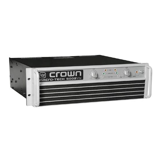
Model: Macro-Tech 5002VZ
Some models may be exported under the name Amcron .
©2000 by Crown International, Inc., P.O. Box 1000, Elkhart, IN 46515-1000 U.S.A. Telephone: 219-294-
8000. Fax: 219-294-8329. Macro-Tech amplifiers are produced by the Professional Audio Unit of Crown
International, Inc. Trademark Notice: PIP,
Amcron ,
®
Crown ,
®
Macro-Tech ,
International, Inc. Other trademarks are the property of their respective owners.
Approved for
THX Theatre
Systems
™
SmartAmp
™
and Grounded Bridge
®
IOC ,
®
ODEP
®
, IQ System
®
and P.I.P.
®
™
are trademarks and
®
are registered trademarks of Crown
128313-2
8/00
Advertisement
Table of Contents

Related Manuals for Crown Macro-Tech 5002VZ


Summary of Contents for Crown Macro-Tech 5002VZ
- Page 1 Some models may be exported under the name Amcron . ® ©2000 by Crown International, Inc., P.O. Box 1000, Elkhart, IN 46515-1000 U.S.A. Telephone: 219-294- 8000. Fax: 219-294-8329. Macro-Tech amplifiers are produced by the Professional Audio Unit of Crown International, Inc. Trademark Notice: PIP, ™...
-
Page 2: North America
SUMMARY OF WARRANTY The Crown Audio Division of Crown International, Inc., 1718 West The Crown Audio Division of Crown International, Inc., 1718 West Mishawaka Mishawaka Road, Elkhart, Indiana 46517-4095 U.S.A. warrants to you, the Road, Elkhart, Indiana 46517-4095 U.S.A. warrants to you, the ORIGINAL... -
Page 3: Important Safety Instructions
Macro-Tech 5002VZ Power Amplifier Important Safety Instructions 1) Read these instructions. 2) Keep these instructions. 3) Heed all warnings. 4) Follow all instructions. 5) Do not use this apparatus near water. 6) Clean only with a dry cloth. 7) Do not block any ventilation openings. Install in ac- cordance with the manufacturer’s instructions. -
Page 4: Magnetic Field
The information furnished in this manual does not include all of the details of design, production, or variations of the equipment. Nor does it cover every possible situation which may arise during installation, operation or mainte- nance. If your unit bears the name “Amcron,” please substitute it for the name “Crown” in this manual. If you need special assistance beyond the scope of this manual, please contact our Technical Support Group. -
Page 5: Table Of Contents
Macro-Tech 5002VZ Power Amplifier CONTENTS 1 Welcome ................. 8 1.1 Why So Much Power? ............8 1.2 Unpacking ................ 8 1.3 Features ................9 2 Facilities ................10 3 Installation ................13 3.1 Mounting ................ 13 3.2 Cooling ................13 3.3 Wiring ................ - Page 6 3.12 Wire Size Nomograph ............. 19 3.13 Loudspeaker Fuse Nomograph ..........20 Indicators ................22 Macro-Tech 5002VZ Indicator States ........23 Input Sensitivity, LOI and Compressor Switches ..... 26 Channel 1 VZ Mode Switch (Behind Filter) ......27 A Typical Power Supply ............29 Music Waveforms ..............
-
Page 7: Welcome
1.1 Why So Much Power? do, save all packing materials so you will have them The Macro-Tech 5002VZ can deliver up to 2,500 watts if you ever need to transport the unit. NEVER SHIP per channel into 2-ohm stereo loads or 5,000 watts THE UNIT WITHOUT THE FACTORY PACK. -
Page 8: Features
Macro-Tech 5002VZ Power Amplifier 1.3 Features The Macro-Tech 5002VZ uses the very latest technology sor that can be set for fast or slow attack and release and miniaturized design to provide the highest power and times. value for its size, weight and price. Its patented Grounded ❏... -
Page 9: Facilities
Macro-Tech 5002VZ Power Amplifier Fig. 2.1 Front Facilities 2 Facilities A. Dust Filters parator) indicators, they flash brightly with a 0.1 second The dust filters remove large particles from air drawn in hold delay if there is a difference of 0.05% or more be- by the cooling fans. -
Page 10: Front Facilities Behind The Filter Grille
Macro-Tech 5002VZ Power Amplifier Fig. 2.2 Front Facilities behind the Filter Grille mode for each power supply. The switches are located amplifier should be off for at least 10 seconds be- behind the top dust filter about 1.75 inches (4.5 cm) fore changing this switch (see Section 3.3). -
Page 11: Rear Facilities
Macro-Tech 5002VZ Power Amplifier Fig. 2.3 Rear Facilities P. Balanced Phone Jack Inputs N. Output Connectors This high-current output block is provided for output A balanced ¼-inch (6.35-mm) phone jack for each channel is provided on the PIP2-FXQ. These phone connection. -
Page 12: Installation
3.1 Mounting levels. Refer to Section 7 for detailed information on ther- The Macro-Tech 5002VZ is designed for standard mal dissipation. 19 inch (48.3 cm) rack mounting and “stack” mounting When mounting the amplifier in a rack cabinet, the back without a cabinet. -
Page 13: Wiring
Macro-Tech 5002VZ Power Amplifier 3.3 Wiring reo/mono switch. Turn off the amplifier and wait at least 10 seconds before changing this switch or in- The following instructions describe the most common ternal damage to the circuitry may result. There are ways to install your amplifier in a sound system. -
Page 14: Bridge-Mono Operation
Macro-Tech 5002VZ Power Amplifier Note: A method for paralleling multiple amplifiers for fail- Note: The Channel 2 input jack and level control are safe redundancy is available from Crown’s Technical disconnected in Bridge-Mono mode. A signal feeding Support Group. Channel 2 will have no effect on the output. -
Page 15: Parallel-Mono Operation
Macro-Tech 5002VZ Power Amplifier 3.3.3 Parallel-Mono Operation input. Both outputs will now receive the signal from the Parallel-Mono mode is intended for driving loads with a Channel 1 input. total impedance of less than 4 ohms (see Section 3.3.2 Note: The Channel 2 input jack and level control are if the load is 4 ohms or greater). -
Page 16: Input Connection
Macro-Tech 5002VZ Power Amplifier 3.3.4 Input Connection Both the XLR and ¼-inch phone jack inputs are bal- anced. They have a minimum impedance of 10 K ohms (5 K ohms with unbalanced wiring) and will accept the line-level output of most devices. The XLR connectors... -
Page 17: Output Connection
Macro-Tech 5002VZ Power Amplifier SOLVING INPUT PROBLEMS The LOI circuitry will also help to avoid this potential problem. It includes a second-order Bessel low-pass Sometimes large infrasonic (subaudible) frequencies filter with a –3 dB frequency of 50 kHz. are present in the input signal. This can cause output clipping and off-center woofer cone movement. -
Page 18: Wire Size Nomograph
Macro-Tech 5002VZ Power Amplifier .0002 .0002 Source Resistance (Ohms) Use Good Connectors .0004 .0006 1. To prevent possible short circuits, do not .001 expose the loudspeaker cable connectors. 2. Do not use connectors that might acciden- .002 Damping Factor tally tie two channels together when making 20,000 .004... -
Page 19: Additional Load Protection
Macro-Tech 5002VZ Power Amplifier 3.3.6 Additional Load Protection 7. If the size of the cable exceeds what you want to use, (1) find a way to use shorter cables, like using an IQ Your amplifier can generate high power levels. If your... -
Page 20: Ac Mains Power Requirements
The proper procedures are outlined inside 3.4 AC Mains Power Requirements the top cover of the amplifier. Contact Crown’s Techni- Each Macro-Tech 5002VZ is supplied from the factory cal Support Group for more information. with an appropriate AC cord. Units configured for 100 WARNING: Risk of severe electric shock. -
Page 21: Operation
4.1 Precautions that can be used to help to identify a problem that The Macro-Tech 5002VZ is protected from internal and causes a power supply to be put in “standby.” These external faults, but you should still take the following indicators are described in Section 4.3.2. -
Page 22: Macro-Tech 5002Vz Indicator States
Macro-Tech 5002VZ Power Amplifier Fig. 4.2 Macro-Tech 5002VZ Indicator States Page 23 Reference Manual... -
Page 23: Protection Systems
0.1 second hold delay to show that an input sig- nal is too large and must be compressed at the input. The Macro-Tech 5002VZ provides extensive protection and diagnostics capabilities. Protection systems in- The indicators will also stay on brightly for a channel clude ODEP , “standby”... -
Page 24: Transformer Thermal Protection
4.3.4 Power Supply Fuses If the OVER-VOLT/THERM indicator is lit for one channel, transformer thermal protection has been An internal fuse protects the Macro-Tech 5002VZ’s low- activated. An overvoltage condition always causes voltage power supply. The low-voltage power supply both indicators to light. If both indicators are lit, test fuse will not blow unless something is wrong with the your AC mains voltage. -
Page 25: Controls
Macro-Tech 5002VZ Power Amplifier The high-voltage power supplies are also protected by The three-position input sensitivity switches are lo- internal fuses. With rated loads and output levels, a fuse cated on the back panel and are factory set to should only shut down its channel in the rare instance of 0.775 volts for standard 1 kHz power*. -
Page 26: Filter Cleaning
Macro-Tech 5002VZ Power Amplifier brightly, and the compressor to compress the input sig- The switch for Channel 1 is located on the left side, and nal (if it is turned on). If an input signal has too much the switch for Channel 2 is on the right. -
Page 27: Technical Information
This patented approach is called ODEP or Output Device Emulation Protection. It maximizes the The heat sinks for the Macro-Tech 5002VZ are fabri- available output power and eliminates overheating, the cated from custom milled fin stock that provides an ex- major cause of output device failure. -
Page 28: The Vz Supply
Macro-Tech 5002VZ Power Amplifier VZ POWER SUPPLY pate. Also, the lower the mode of the VZ resistance of the power power supply. POWER POWER TRANSISTOR transistors, the more TRANSISTOR STAGE When the voltage re- voltage you can deliver quirements are high, –... -
Page 29: Circuit Block Diagram
Macro-Tech 5002VZ Power Amplifier Fig. 5.5 Circuit Block Diagram Page 30 Reference Manual... - Page 30 Macro-Tech 5002VZ Power Amplifier also activated any time the first stage is about to be world conditions. These conditions are high instanta- overdriven. The compressor control circuit also sends neous current, excessive temperature, and operation of signals to the display module to indicate IOC or input the output devices outside safe conditions.
-
Page 31: Bridge-Mono Operation
Macro-Tech 5002VZ Power Amplifier 5.3.3 Parallel-Mono Operation The VZ mode switch (S700) has four positions which control how the articulated supply functions. (Two of the With the stereo/mono switch set to PARALLEL MONO, four switch positions are identical because there are the output of Channel 2 is paralleled with that of Chan- only three VZ modes.) In the VZ position, the supply will... -
Page 32: Specifications
Macro-Tech 5002VZ Power Amplifier Signal-to-Noise Ratio: A-weighted: Better than 105 Specifications dB below rated 1 kHz power. The following applies to 120 VAC, 60 Hz units in Stereo Total Harmonic Distortion (THD): 1 kHz rated power, mode with 8-ohm loads and an input sensitivity of 26 0.05% or less true THD. - Page 33 Macro-Tech 5002VZ Power Amplifier Signal/IOC: Each channel has a green front panel Parallel-Mono: Unbalanced, single-channel. Chan- indicator that flashes to show amplifier output. If a nel 1 controls are active; Channel 2 controls are channel’s output waveform differs from its input by removed from operation.
-
Page 34: Minimum Power Matrix
Macro-Tech 5002VZ Power Amplifier Crown specifications are guaranteed for three years. In an effort to provide you with as much information as possible about the high power-producing capabilities of your amplifier, we have created the following power matrices. Minimum Guaranteed Power Specifications Crown’s minimum power specifications represent the absolute smallest amount of output power you can expect from your... -
Page 35: Maximum Power Matrix
The burst power specifications are provided at 0.05% THD which is a practical low distortion condition. Operating the amplifier at levels higher than 0.05% THD can result in output power levels that are higher than those listed in the maximum power matrices. Macro-Tech 5002VZ – Maximum Power (Watts) Maximum Power Notes: Single Cycle Tone Burst... -
Page 36: Typical Frequency Response
Macro-Tech 5002VZ Power Amplifier Fig. 6.3 Typical Frequency Response Fig. 6.4 Typical Damping Factor Fig. 6.5 Typical Output Impedance Page 37 Reference Manual... -
Page 37: Typical Phase Response
Macro-Tech 5002VZ Power Amplifier Measurement +45˚ 0˚ –45˚ ® 10 K 20 K FREQUENCY (Hz) Fig. 6.6 Typical Phase Response –60 Measurement –66 –72 –78 –84 –90 –96 ® 10 K 20 K FREQUENCY (Hz) Fig. 6.7 Typical Crosstalk Page 38... -
Page 38: Ac Power Draw And Thermal Dissipation
This section provides detailed information about the amount of power and current drawn from the AC power The following equation converts power draw in watts to line by the Macro-Tech 5002VZ, and the amount of heat current draw in amperes: produced under various conditions. The calculations presented here are intended to provide a realistic and reliable depiction of the amplifier. -
Page 39: Accessories
Macro-Tech 5002VZ Power Amplifier 8 Accessories 8.1 PIP and PIP2 Modules One advantage of Crown PIP2 compatible amplifiers is For more information on these or other PIPs under de- the ability to customize them using PIP (Programmable velopment, contact your local dealer or Crown’s Techni- Input Processor) and PIP2 modules. - Page 40 Macro-Tech 5002VZ Power Amplifier cluded is a bass-cut (high-pass) filter for each channel. The equalization and bass-cut filters can be bypassed, if desired. Balanced inputs and “daisy-chain” outputs use removable barrier block connectors for quick, solderless connections. P.I.P.-BEQX Same as P.I.P.-BEQC but with XLR connec- IQ-PIP-USP2 is an IQ2 -series component.
-
Page 41: Level Control Security Kit
Macro-Tech 5002VZ Power Amplifier “duck” level, 84 dB of attenuation. A 10-volt DC source for remote control capability is provided. The P.I.P.-EXT (Part M44731-4), available from service, allows the P.I.P.-RPA and other PIP cards to be “extended” outside the amplifier for easy set up. -
Page 42: Service
Macro-Tech 5002VZ Power Amplifier 9 Service This unit has very sophisticated circuitry which should Your repaired unit will be returned via UPS ground. only be serviced by a fully trained technician. This is Please contact us if other arrangements are required. - Page 43 Crown Factory Service Information Shipping Address: Crown International, Inc., Factory Service, Plant 2 SW, 1718 W. Mishawaka Rd., Elkhart, IN 46517 Phone: 1-800-342-6939 or 1-219-294-8200 Fax: 1-219-294-8301 Owner’s Name: _________________________________________________________________________ Shipping Address: ______________________________________________________________________ Phone Number: _____________________________ Fax Number: _____________________________ Model: ________________________ Serial Number: ______________ Purchase Date: ___________ NATURE OF PROBLEM (Be sure to describe the conditions that existed when the problem occurred and what attempts were made to correct it.)
Need help?
Do you have a question about the Macro-Tech 5002VZ and is the answer not in the manual?
Questions and answers