Table of Contents
Advertisement
Quick Links
Download this manual
See also:
Reference Manual
Advertisement
Table of Contents

Subscribe to Our Youtube Channel
Related Manuals for US Robotics Courier USR3500


Summary of Contents for US Robotics Courier USR3500
- Page 1 Courier M2M 3G Cellular Modem USR3500 Getting Started R24.0796.00...
-
Page 2: Important Notice
Limitations of Liability This manual is provided “as is”. Neither Sierra Wireless nor USRobotics makes any warranties of any kind, either expressed or implied, including any implied warranties of merchantability, fitness for a particular purpose, or noninfringement. The recipient of the manual shall endorse all risks arising from its use. - Page 3 HAVE BEEN ADVISED OF THE POSSIBILITY OF SUCH DAMAGES OR THEY ARE FORESEEABLE OR FOR CLAIMS BY ANY THIRD PARTY. Notwithstanding the foregoing, in no event shall Sierra Wireless or USRobotics and/or their respective affiliates aggregate liability arising under or in connection with the Sierra...
-
Page 4: Contact Information
InterDigital Group and MMP Portfolio Licensing. Copyright © 2014 USRobotics. All rights reserved. Trademarks ® USRobotics , Courier and the USRobotics logo are registered trademarks of USRobotics. ® ® ® ® Sierra Wireless , AirPrime... -
Page 5: Document History
Getting Started Document History Version Date Updates 9/25/13 Creation 11/1/2013 First review edits Rev 1.1 9/22/14... -
Page 6: Table Of Contents
4.3. Expansion Interface ................... 20 4.4. Over-Voltage and Over-Current Protection ..........21 4.4.1. Power Supply Input ................21 4.4.2. Electrostatic Discharge ..............21 4.4.3. Main Serial Port ................21 5. USING THE USR3500 ..................22 5.1. Mounting the USR3500 ................22 Rev 1.1 9/22/14... -
Page 7: Rev 1.1 9/22/14 7
6.10. Main AT Commands for the USR3500 ............ 34 6.11. IP Data Connection ................. 35 7. TROUBLESHOOTING THE USR3500 ............... 36 7.1. No Communications with the USR3500 through the Serial Port....36 7.2. Receiving “ERROR” .................. 37 7.3. Receiving “NO CARRIER” ................. 37 8. -
Page 8: Rev 1.1 9/22/14 8
Getting Started 10. REFERENCE DOCUMENTS ................46 10.1. Firmware Documentation ................ 46 10.2. Ethernet Card Documentation ..............46 10.3. Firmware Upgrade Documentation ............46 11. LIST OF ABBREVIATIONS ................47 12. PRODUCT LABELING ..................50 Rev 1.1 9/22/14... -
Page 9: List Of Figures
Getting Started List of Figures Figure 1. Mounting Bracket Dimensions ..............13 Figure 2. USR3500 ....................16 Figure 3. Mounting Brackets .................. 22 Figure 4. Mounting the Modem ................22 Rev 1.1 9/22/14... -
Page 10: List Of Tables
Table 16. AT+CPIN Main Responses ..............33 Table 17. Main AT Commands used for the USR3500 .......... 34 Table 18. No Communications with the USR3500 Through the Serial Port ... 36 Table 19. Receiving a “No Carrier” Message ............38 Table 20. -
Page 11: Overview
Getting Started Overview Overview The USR3500 is a programmable modem bundled with our USRobotics Courier M2M Open AT application. The USR3500 industrial grade USB and serial modem supports penta-band 3G HSPA+ with dual antenna receive diversity and quad band 2G GSM/GPRS/EDGE. -
Page 12: Packaging
Getting Started Packaging Packaging 2.1. Contents The table below summarizes the list of items delivered with the USR3500. Table 1. Included contents with the USR3500 Standard Package Penta Band Antenna Universal Power Supply Serial Data Cable Mounting Brackets Quick Installation Guide 2.2. -
Page 13: Serial Data Cable
Table 3. Serial Data Cable Description Length: 1.5M Connection: DB9F (PC) to HD15M 2.2.3. Two Mounting Brackets Please refer to section 5.1 Mounting the USR3500 for more information regarding the mounting brackets. Figure 1. Mounting Bracket Dimensions Rev 1.1 9/22/14... -
Page 14: Power Supply
Getting Started Packaging 2.2.4. Power Supply Table 4. Power Supply Description Rev 1.1 9/22/14... - Page 15 Getting Started Packaging Input Voltage 100-240VAC Output Voltage 12VDC Output Current 2.08A, No Minimum Load required Output Power (Rated) 25W MAX Rev 1.1 9/22/14...
-
Page 16: Hardware
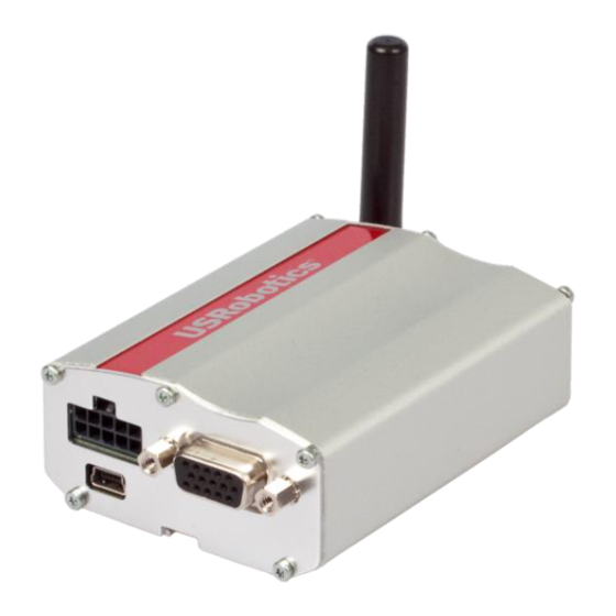
Getting Started Hardware Hardware 3.1. Overall Dimensions Table 5. USR3500 Physical Dimensions Length 89 mm Width 60 mm Thickness 30 mm Weight 125g Figure 2. USR3500 Rev 1.1 9/22/14... -
Page 17: Connections
Audio Interface 2 GPIOs LED Status Indicator 3.3.2. Internal Expansion Interface 1 Secondary Serial Port (UART2) 6 GPIOs 2 SPI Bus 1 ADC 1 PCM 1 Interrupt Reset access to the embedded module 2.8V supply from the USR3500 Rev 1.1 9/22/14... -
Page 18: Environmental Compliance
Environmental Compliance 3.4.1. RoHS Directive Compliant The USR3500 is compliant with RoHS Directive 2011/65/EC which sets limits for the use of certain restricted hazardous substances. This directive states that “from 1st July 2006, new electrical and electronic equipment put on the market does not contain lead, mercury, cadmium, hexavalent chromium, polybrominated biphenyls (PBB) or polybrominated diphenyl ethers (PBDE)”. -
Page 19: Features
Features This section details the features available on the USR3500. 4.1. Features Refer to the table below for the list of basic features available on the USR3500. Table 6. USR3500 Basic Features Features Description AT command programmable Allows standalone operation... -
Page 20: Supported Bands
4.3. Expansion Interface The USR3500 offers a 50-pin expansion interface. It is an additional interface for customers who wish to expand their application features by simply plugging in a card through the mating connector of the interface. -
Page 21: Over-Voltage And Over-Current Protection
Over-Voltage and Over-Current Protection 4.4.1. Power Supply Input The USR3500 power supply input is protected against transient voltage peaks over +32V. When the input voltage exceeds 32V, the supply voltage is automatically disconnected in order to protect the internal electronic components from over-voltage. -
Page 22: Using The Usr3500
Mounting the USR3500 The mounting brackets help hold and secure the USR3500 on a support. Figure 3. Mounting Brackets To mount the USR3500 on its support, fasten it using the mounting brackets as shown in the figure below. Mounting brackets Figure 4. -
Page 23: Setup
Extracting the SIM Card for more details on how to insert and extract the SIM card from the USR3500.) 2. Slide the SIM lock switch to lock the SIM card in the USR3500. 3. Connect the main antenna to the main RF connector. -
Page 24: Inserting The Sim Card
Refer to section 6.10 Main AT Commands for the list of commands used to configure the USR3500. Note: For automotive applications, it is recommended to connect the DC-IN line of the USR3500 directly to the positive terminal of the battery. 5.2.1. -
Page 25: Extracting The Sim Card
4. Slide the SIM lock switch to lock the SIM card in the USR3500. 5.2.2. Extracting the SIM Card In order to extract the SIM card from the USR3500, follow the procedures below: 1. Open the SIM lock switch by sliding it to the left. Rev 1.1... -
Page 26: Operational Status
4. Extract the SIM card from the USR3500. 5.3. Operational Status The USR3500’s operational status is defined by a red LED, which is located between the back plate and the secondary RF interface. Rev 1.1 9/22/14... - Page 27 Getting Started Using the USR3500 Status LED If the LED of the USR3500 is flashing slowly, the modem is switched ON and is registered in a network (Idle mode). Refer to the Reference Guide at http://www.usr.com/support/3500 for more information about the LED status indicator.
-
Page 28: Communicating With The Usr3500
AT Commands Interface Guide at http://www.usr.com/support/3500. 6.1. Communications Testing To perform a communications test after the USR3500 has been setup using the RS232 serial port connection, do the following: Connect the RS232 port between the external application COM port (DTE) and the USR3500 (DCE). -
Page 29: Verifying The Received Signal Strength
No measure available 6.3. Verifying the Network Registration Using a communication software such as HyperTerminal, enter AT+CREG? to verify the network registration of the USR3500. Refer to the table below for the list of main responses returned. Table 9. AT+CREG? Main Reponses... -
Page 30: Checking The Band Selection
Quad-band mode 850/900E (extended)/1800/1900MHz is selected Where: When x = 0, the band has not been modified since the last boot of the USR3500; When x = 1, the band has been modified since the last boot of the USR3500, and will have to be reset in order to take any previous modification(s) into account. -
Page 31: Switching Bands
Switch to quad band mode 850/900E (extended)/1800/1900MHz Where: When x = 0, the USR3500 will have to be reset to start on the specified band(s); When x = 1, the band switch is effective immediately. However, this mode is forbidden while in Communication mode and during the USR3500’s initialization. -
Page 32: Table 14. At+Wubs Band Selection
Where: y = Band frequency configuration (bit field) in HEX format. x = Optional reset parameter (0 means the USR3500 will have to be reset to start on the specified band(s), and 1 means the band switch is effective AT+WUBS=y, x immediately. -
Page 33: Checking The Pin Code Status
6.8. Enabling/Disabling the Flash LED The USR3500 has a red LED indicator that shows the status of the GSM network. It is possible to disable this LED during Sleep mode in order to reduce power consumption. Using a communication software such as HyperTerminal, enter:... -
Page 34: Firmware Upgrade Procedure
6.10. Main AT Commands for the USR3500 The table below lists the main AT Commands required for starting the USR3500. For other available AT Commands, refer to the AT Commands Interface Guide at http://www.usr.com/support/3500. -
Page 35: 6.11. Ip Data Connection
Communicating with the Getting Started USR3500 Feature/Function AT Command Response Description Communication established. ATD<phone number>; PIN code not entered (with +CMEE = +CME ERROR: 11 1 mode*). Initiate a call (Do not forget the « ; AOC credit exceeded or »... -
Page 36: Troubleshooting The Usr3500
7.1. No Communications with the USR3500 through the Serial Port If the USR3500 does not respond to AT commands through the serial port, refer to the table below for possible causes and the corresponding solutions. Table 18. No Communications with the USR3500 Through the Serial Port... -
Page 37: Receiving "Error
Troubleshooting the USR3500 Receiving “ERROR” 7.2. The USR3500 returns an “ERROR” message (in reply to an AT command) in the following cases: The AT command syntax is incorrect. In this case, check the command syntax (refer to the AT Commands Interface Guide at http://www.usr.com/support/3500). -
Page 38: Table 19. Receiving A "No Carrier" Message
AT command: network? AT+CBST=0,0,3 If the USR3500 returns a “NO CARRIER” message, you may retrieve the extended error code by using the AT Command AT+CEER. Refer to the following table for the interpretation of extended error codes. - Page 39 Getting Started Troubleshooting the USR3500 Error Code Diagnosis Hint Check your subscription. (Is data subscription Requested facility not subscribed available?) ACM equal or greater than ACMmax The credit of your pre-paid SIM card has expired. Call barring on outgoing calls...
-
Page 40: Usr3500 Accessories
6-Wire Cable Accessory Color Coding Cable Accessory Color DC-IN BLACK VREF GREEN GPIO35 ORANGE ON/OFF YELLOW GPIO25/INT1 BROWN Note: The above items are ONLY considered as optional accessories of the USR3500. They are NOT considered as part of the USR3500. Rev 1.1 9/22/14... -
Page 41: Gps Antenna
8.1.2. GPS Antenna Table 23. GPS Antenna Description Weight < 110 grams Size 49x39x14mm Cable RG174/U 3meters Mechanical Connector MMCx m. right angle Mounting Magnetic base Housing Black Center Frequency 1575.42MHz ± 3 MHz V.S.W.R 1.5 : 1 Band Width ±5 MHz 50Ω... -
Page 42: Safety Recommendations
Getting Started Safety Recommendations Safety Recommendations 9.1. General Safety For the efficient and safe operation of your programmable modem, please read the following information carefully. It is important to follow any special regulations regarding the use of radio equipment due in particular to the possibility of radio frequency (RF) interference. - Page 43 There may be a hazard associated with the operation of your USR3500 close to inadequately protected personal medical devices such as hearing aids and pacemakers.
-
Page 44: Rf Safety
9.3. Vehicle Safety Do not use your USR3500 while driving, unless equipped with a correctly installed vehicle kit allowing ‘Hands-Free’ Operation. Respect national regulations on the use of cellular telephones in vehicles. Road safety always comes first. -
Page 45: Care And Maintenance
Do not expose the USR3500 to any extreme environment where the temperature or humidity is high. Do not use or store the USR3500 in dusty or dirty areas. Its moving parts can be damaged. Do not attempt to disassemble the modem. There are no user serviceable parts inside. -
Page 46: 10. Reference Documents
10. Reference Documents The documents referenced herein are provided by USRobotics. Visit the USRobotics website at for the latest documentation available. http://www.usr.com/support/3500 10.1. Firmware Documentation AT Commands Interface Guide Customer Release Notes for Firmware 7.52 A1 10.2. Ethernet Card Documentation Ethernet Card User Guide 10.3. -
Page 47: 11. List Of Abbreviations
11. List of Abbreviations Abbreviation Definition Alternating Current Accumulated Call Meter Adaptive Multi-Rate ® ATtention (prefix for Wireless CPU commands) Clock CMOS Complementary Metal Oxide Semiconductor Coding Scheme Clear To Send Decibel Decibel relative to the Carrier power Decibel relative to an Isotropic radiator Decibel relative to one milliwatt Direct Current Data Carrier Detect... - Page 48 Getting Started List of Abbreviations Abbreviation Definition HSPA High Speed Packet Access HSUPA High Speed Uplink Packet Access Input International Electrotechnical Commission Internal Expansion Socket IESM Internal Expansion Socket Module IMEI International Mobile Equipment Identification Input / Output Light Emitting Diode MAXimum Mobile Equipment MICrophone...
-
Page 49: Getting Started
Getting Started List of Abbreviations Abbreviation Definition SRAM Static RAM TCP/IP Transmission Control Protocol / Internet Protocol TDMA Time Division Multiple Access Typical Urban fading profile TUHigh Typical Urban, High speed fading profile Transmit TYPical UMTS Universal Mobile Telecommunications System VSWR Voltage Stationary Wave Ratio Rev 1.1... -
Page 50: 12. Product Labeling
12. Product Labeling A product label is located at the back of the USR3500 and provides additional information about the modem. The labels provide the following information: Serial number and barcode Product Name Model number WEEE logo Qualcomm CDMA logo... - Page 51 Rev 1.1 9/22/14...
Need help?
Do you have a question about the Courier USR3500 and is the answer not in the manual?
Questions and answers