
Related Manuals for ICP TSTAT0710


Summary of Contents for ICP TSTAT0710
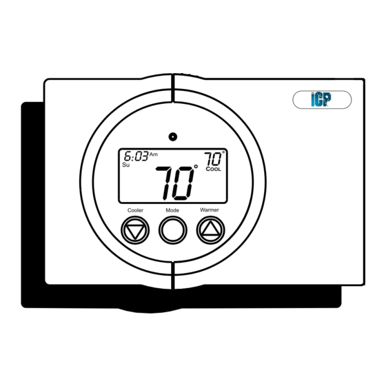
- Page 1 DIGITAL THERMOSTAT P/N TSTAT0710 Installation Instructions HEAT COOL 6:03 & Warmer Cooler Mode HEAT PUMP MULTI-STAGE PROGRAMMABLE International Comfort Products 2003...
-
Page 2: Table Of Contents
WARNING THE NEW THERMOSTAT. International Comfort Products 2003 P/N TSTAT0710 This device complies with Part 15 of the FCC rules. Operation is subject to the following 2 conditions: (1) This device may not cause harmful interference, and (2) This device must accept any interference received, including interference that may cause undesired operation. -
Page 3: Preparation
STEP #1 PREPARATION Proper installation of the thermostat will be 6:03 accomplished by following these step Cooler Mode Warmer by step instructions. If you are unsure about any of these steps, call a qualified technician for assistance. Assemble tools 6:03 Cooler Mode Warmer... -
Page 4: Remove Old Thermostat
STEP #2 REMOVE & REPLACE OLD THERMOSTAT Remove the cover of the old thermostat. 6:03 If it does not come off easily check for Cooler Mode Warmer screws. Loosen the screws holding the thermostat 6:03 base or subbase to the wall, and lift away. Cooler Mode Warmer... -
Page 5: Wire Connections
STEP #3 WIRE CONNECTIONS If the terminal designations on your old 6:03 thermostat do not match those on the Cooler Mode Warmer new thermostat, refer to the chart below, or the wiring diagrams that follow. Install on the Wire from the old thermostat new thermostat Function... -
Page 6: Wiring Diagrams
Sample Wiring Diagrams 5 Wire, 1 Stage Cooling, 1 Stage Gas Heat Residential Gas or Electric Heat *, Electric Cool, split systems & package units Thermostat 24 vac common fan relay compressor relay 1st stage heat circuit 24 vac return * If using electric heat this option must be selected on during advanced setup. - Page 7 Sample Wiring Diagrams 6 Wire, 2 Stage Cooling, 1 Stage Heat Residential 2 Stage Cooling, with Gas or Electric Heat* Thermostat 24 vac common fan relay compressor relay 1st stage heat circuit 24 vac return 2nd stage compressor relay * If using electric heat, this option must be selected during advanced setup.
- Page 8 Sample Wiring Diagrams Commercial Gas or Electric Heat ***, 7 Wire, 2 Stage Cooling, 2 Stage Heat Electric Cool, split systems & package units including Commercial Heat Pumps ** Thermostat 24 vac common fan relay compressor relay 1st stage heat circuit 24 vac return 2nd stage compressor relay 2nd stage heat circuit...
-
Page 9: Calibration
Sample Wiring Diagram 6 Wire, 1 Stage Cooling, 2 Stage Heat, Heat Pump * Most residential split and package heat pumps with auxiliary heat Thermostat 24 vac common fan relay compressor relay 1st stage heat circuit 24 vac return 2nd stage heat circuit * The heat pump option must be selected on during advanced setup. -
Page 10: Test Operation
STEP #4 TEST OPERATION 6:03 Turn the power on to the Heating/Air Cooler Mode Warmer Conditioning system. Press the MODE button repeatedly until 6:03 the HEAT icon appears on the display. Cooler Mode Warmer Press the Up or Down buttons until the set temperature is 10 degrees above room temperature. -
Page 11: Troubleshooting
TROUBLESHOOTING 6:03 SYMPTOM: When using 4 wires (R, G, W, Y), Cooler Mode Warmer the air conditioning equipment tries repeatedly to turn on, but cannot. At times the display dims or disappears. CAUSE: There is not enough power available to "power share". REMEDY: Connect a 270 ohm, 10 watt power resistor at the furnace as shown below. - Page 12 TROUBLESHOOTING 6:03 SYMPTOM: The air conditioning does not Cooler Mode Warmer attempt to turn on. CAUSE: The cooling setpoint is set too high. REMEDY: Consult the Owner's Manual in the Setup section to lower the cooling setpoint limit. 6:03 SYMPTOM: The heating does not attempt Cooler Mode Warmer...
- Page 13 "conventional" (non heat pump) system. REMEDY: Consult the Owner's Manual in the Advanced Setup section to turn off the heat pump. Slimline P/N TSTAT0710 Tested to Comply with FCC Standards FOR HOME OR OFFICE USE 4Z95 P/N 88-416 Page 12...
Need help?
Do you have a question about the TSTAT0710 and is the answer not in the manual?
Questions and answers