Sign In
Upload
Download
Table of Contents
Contents
Add to my manuals
Delete from my manuals
Share
URL of this page:
HTML Link:
Bookmark this page
Add
Manual will be automatically added to "My Manuals"
Print this page
×
Bookmark added
×
Added to my manuals
Manuals
Brands
Audi Manuals
Engine
V8
Service
Audi V8 Service
Self-study programme 217
Hide thumbs
1
2
Table Of Contents
3
4
5
6
7
8
9
10
11
12
13
14
15
16
17
18
19
20
21
22
23
24
25
26
27
28
29
30
31
32
33
34
35
36
37
38
39
40
41
42
43
44
45
46
47
48
49
50
51
52
page
of
52
Go
/
52
Contents
Table of Contents
Bookmarks
Table of Contents
Table of Contents
Introduction
Technical Data
Engine - Mechanics
Crankgear
Engine Mounting
Engine Lubrication
Cooling Circuit
Cylinder Head
Five-Valve Technology
Roller Rocker
Camshaft Adjuster
Toothed-Belt Drive; Cylinder-Head Seal
Cylinder-Head Cover Seal
Exhaust Manifold
Engine - Motronic Subsystems
Variable Intake Manifold
Secondary Air System
Engine Management
System Overview
Function Diagram
Quick-Start Functions
Camshaft Position Sensor
Engine Run-Down Sensor
Electronic Throttle Function
CAN Bus Interfaces
Additional Signals/ Interfaces
Service
Advertisement
Quick Links
1
Technical Data
2
Crankgear
3
Engine Mounting
4
Cooling Circuit
5
Variable Intake Manifold
6
Service
Download this manual
Service.
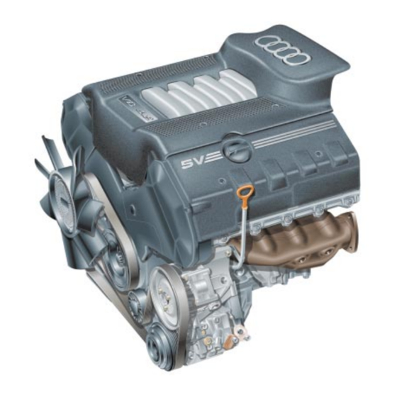
The V8-5V Engine
Construction Features and Functions
Self-Study Programme 217
For internal use only
Table of
Contents
Previous
Page
Next
Page
1
2
3
4
5
Advertisement
Table of Contents
Need help?
Do you have a question about the V8 and is the answer not in the manual?
Ask a question
Questions and answers
Related Manuals for Audi V8
Engine AUDI V6 BITURBO Manual
Self-study programme 198 (73 pages)
Engine Audi V5 Service
Self-study programme 217 (52 pages)
Engine Audi 4.2-litre V8 FSI Service Training
(48 pages)
Engine Audi 4.2-liter V8 FSI Service Training
(48 pages)
Engine Audi AMB Service Manual
A4 quattro 2005 (650 pages)
This manual is also suitable for:
V5
V8-5v
Table of Contents
Save PDF
Print
Rename the bookmark
Delete bookmark?
Delete from my manuals?
Login
Sign In
OR
Sign in with Facebook
Sign in with Google
Upload manual
Upload from disk
Upload from URL


Need help?
Do you have a question about the V8 and is the answer not in the manual?
Questions and answers