Table of Contents
Advertisement
Advertisement
Table of Contents

Related Manuals for Audi 4.2-litre V8 FSI


Summary of Contents for Audi 4.2-litre V8 FSI
- Page 1 Service Training Audi 4.2-litre V8 FSI engine Self-Study Programme 377...
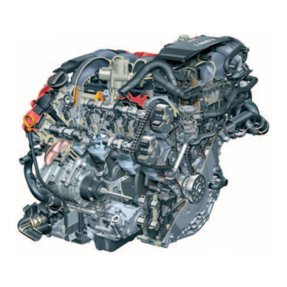
- Page 3 Special features of the current Audi vee engine family are the 90-degree included angle between the cylinder banks and the spacing of 90 mm between the cylinders. The first member of the family was the 3.2-litre V6 FSI engine. The 4.2-litre V8 FSI engine is also a member of this family.
-
Page 4: Table Of Contents
Vacuum hoses in the Audi RS4 ........ - Page 5 System overview, Audi Q7 (Bosch MED 9.1.1) ......36 System overview, Audi RS4 (Bosch MED 9.1) ......38 Operating modes .
-
Page 6: Introduction
Introduction The 4.2-litre V8 FSI engine is supplied in the new The following main objectives were set for Audi Q7, Audi A6, Audi A8 and in the RS4. the development of the Q7 engine: – High specific engine power: 257 kW/350 bhp out of 4.2 litres (15 bhp more than MPI engines) –... - Page 7 The main technical differences between the base Technical features engine and the high-revving engine lie in the – Petrol direct injection following modules: – Homogeneous-charge mode – Roller cam followers with hydraulic backlash – Cranktrain compensation – Timing gear – Flywheel-side chain drives for camshafts and –...
-
Page 8: Specifications
Introduction Torque/power curve Max. torque in Nm V8 FSI basic engine in Q7 V8 FSI high-revving engine in RS4 Max. power output in kW V8 FSI basic engine in Q7 V8 FSI high-revving engine in RS4 5000 2000 7000 9000 Engine speed in RPM Specifications Engine code... -
Page 9: Engine Mechanicals
Engine mechanicals Cranktrain Cylinder block The cylinder crankcase has a closed-deck design. *Aluminium alloys are classed as hypoeutectic or The closed-deck design is stronger than the open- hypereutectic, depending on their silicon content. deck design. "Alusil" has a hypereutectic silicon content of 16 to In an open-deck cylinder block, the water jacket for 18 % so that primary silicon is precicipated on cooling the cylinders is open at the top. - Page 10 Engine mechanicals Crankshaft Modifications to high-revving engine The crankshaft runs on five bearings and is made of At the very high engine speeds, axial vibration high-alloy tempering steel (42CrMoS4). It is 90° occurs due to the unbalance in the single-mass cranked and has no conrod journal offset.
- Page 11 Con-rod Cracked con-rods made of 36MnVS4 are used in the basic engine while the conventionally split con-rods in the RS4 engine are made of 34CrNiMo8 for strength. In addition, the geometry of the con-rods was reduced for the high-revving engine and the toler- ances were reduced.
-
Page 12: Crankcase Ventilation
Engine mechanicals Crankcase ventilation The crankcase is ventilated through both cylinder After the blow-by gas has passed through the fine heads. oil separator, the gas flows into the intake manifold The valve hoods incorporate a large settling space. downstream of the throttle valve. This space acts as a gravity-type oil separator. - Page 13 Function of fine oil separator Blow-by gas volume is dependent on engine load The separated oil is collected in an oil reservoir and RPM. The fine oil ("oil spray") is separated by beneath the cyclones. The oil cannot drain out of means of a cyclone separator.
-
Page 14: Chain Drive
Chain drive B Chain drive C 377_012 Chain drive D The timing gear concept is identical in all Audi vee- engine series. The chain drive runs on two planes. The camshafts in the basic engine are driven by 3/8“ simplex roller chains. -
Page 15: Drive, Ancillary Units
Ancillary units drive The oil pump, water pump, power steering pump and the compressor are driven by chain drive D. The chain is driven directly by the crankshaft, deflected by an idler gear and drives the chain sprocket seated on the gear module. Air conditioner compressor Chain drive D Coolant pump... -
Page 16: Cylinder Head
Engine mechanicals Cylinder head Different features of the high-revving engine The cylinder heads are based technically on the well-known Audi four-valve FSI cylinder heads. To match the higher engine power output and RPM, the following cylinder head components were Specifications modified:... - Page 17 Crankcase breather Valve hood Hall sensor High-pressure fuel pump with fuel metering valve 377_015 Intake adjuster Assembled camshafts Exhaust adjuster with return spring 377_080...
-
Page 18: Oil Circulation System
Cylinder bank 1 Cylinder bank 2 Oil filter module Chain tensioner Hydraulic camshaft adjustment Oil cooler (coolant) Oil pressure regulator Oil pump (gear) Thermostat Features exclusive to the Audi RS4 377_028 Oil cooler (air) -
Page 19: Oil Pump And Oil Filter Module
Oil pump The oil pump is situated above the oil pan. The oil is drawn in through the filter in the bottom of the sump and simultaneously through the engine return duct while driving. All engine lubrication points are swept from the pressurised oil side. -
Page 20: Oil Pan Audi Rs4
Oil circulation system Sump in the Audi RS4 Especially in a sports car, a reliable supply of oil in all driving situations is vitally important. The oil supply system in the high-revving engine was designed for racing applications in which it is subjected to lateral acceleration of up to 1.4 g. -
Page 21: Oil Circuit
Oil circulation system 377_059 Pressurised oil downstream of filter Pressurised oil upstream of filter... -
Page 22: Cooling System
Cooling system Cooling system in the Audi Q7 Heater heat exchanger Expansion tank Coolant temperature sender Coolant pump Alternator Oil cooler Thermostat Radiator 377_030 The cooling system in the new V8 engines was A map-controlled coolant thermostat is used in the configured as a longitudinal-flow cooling system. -
Page 23: Cooling System In Audi Rs4
Cooling system in the Audi RS4 Coolant run-on pump V51 Non-return valve Coolant thermostat for additional cooler 377_031 Additional cooler, right Additional cooler, left Coolant pump and thermostat No map-controlled coolant thermostat is used in the high-revving engine. To achieve more effective cooling, two additional coolers are used. -
Page 24: Air Circulation System
In the upper RPM range, the short intake manifold path is activated. This positionproduces an increase in engine power output. Intake system in the Audi Q7 Throttle valve module Variable inlet manifold Hot-film air mass meter (HFM5) Hot-film air mass meter (HFM5) - Page 25 At this engine speed, the intake manifold change- speeds higher than 200 kph. over valve would be switched to the short path for higher power output. Intake system in the Audi RS4 Air intake Hot-film air mass meter (HFM5) Throttle valve module...
-
Page 26: Vacuum Hoses In The Audi Rs4
Air circulation system Vacuum hoses in the Audi RS4 The conventional method of supplying vacuum to This means that connecting a vacuum line down- the brake servo and the engine components is stream of the throttle valve would offer little pros- problematic in the case of FSI engines. - Page 27 For this reason, in both engine versions, the requi- In this case, the vacuum produced by the suction jet site vacuum is produced by a suction jet pump and, pump is not enough to sufficiently evacuate the if necessary, additionally by an electrical vacuum brake servo.
-
Page 28: Vacuum Hoses In The Audi Q7
Air circulation system Vacuum hoses in the Audi Q7 Secondary air pump Air filter Evaporator casing extraction valve Vacuum pump for brakes V192 Suction jet pump (entrainment pump) with non-return valve Combination valve Brake servo Brake servo Brake servo pressure sensor G294... - Page 29 Note The illustrations show the vacuum hoses. The fitting locations may deviate from those shown here. Secondary air pump relay J299 Evaporator casing from fuel tank 377_068...
-
Page 30: Fuel System
Fuel system Fuel system in the Audi Q7/RS4 Fuel metering valve -2- N402 Fuel metering valve N290 High-pressure fuel pump 2 High-pressure fuel pump 1 Fuel pressure sender, low pressure G410 Leakage line Low-pressure system in the Audi Q7 Reference... - Page 31 Fuel pressure sender, high pressure G247 Fuel distributor (rail) 2 to the injectors of cylinders 5-8 N83-N86 Pressure limiting valve (136 bar) Fuel distributor (rail) 1 Injectors, cylinders 1-4 N30-N33 377_033 Fuel filter integrated in tank 377_036 Return line Fuel tank Fuel pump (pre-supply pump) G6 Fuel pump...
-
Page 32: Exhaust System
During the development of the exhaust system, special emphasis was placed on optimising flow resistance. The clamping flange system used in the 2.0-litre FSI engine has proved highly advantageous in this regard. Audi Q7 Audi RS4 Each cylinder bank has its own exhaust pipe. -
Page 33: Exhaust Flap Control In The Audi Rs4
Exhaust flap control Audi RS4 A further difference is the layout; one exhaust flap is Function located downstream of each of the rear silencers. The exhaust flaps are fitted to give the engine a The exhaust flaps are switched by a vacuum sporty sound. -
Page 34: Secondary Air System
Exhaust system Secondary air system The secondary air system ensures that the catalytic Operating mode in the Q7 converter heats up more quickly and is available sooner after a cold start. During the warm-up phase, the engine control unit J623 activates secondary air pump V101 via the Principle secondary air pump relay J299. - Page 35 Operating mode in the RS4 The secondary air system operates in much the The basic engine in Q7 and the high-revving engine same way as that in the Q7 engine. The difference in RS4 have different fitting locations for the here lies in the way the combination valves open secondary air system.
-
Page 36: Engine Management
Engine management System overview - Audi Q7 (Bosch MED 9.1.1) Sensors Air mass meter G70 Air mass meter 2 G246 Intake air temperature sensor G42 Accelerator pedal position sender G79 Accelerator pedal position sender 2 G185 Engine speed sender G28 Knock sensors 1–4... - Page 37 Actuators Starter motor relay J53, starter motor relay -2- J695 Motronic current supply relay J271 Engine component current supply relay J757 Fuel pump control unit J538 Fuel pump (pre-supply pump) G6 Injectors, cylinders 1-8 N30-N33, N83-N86 Throttle valve module J338 Throttle valve drive (electric power control) G186 Ignition coils N70, N127, N291, N292, N323-N326 Cylinders 1-8...
-
Page 38: System Overview, Audi Rs4 (Bosch Med 9.1)
Engine management System overview - Audi RS4 (Bosch MED 9.1) Sensors Air mass meter G70 Intake air temperature sensor G42 Accelerator pedal position sender G79 Accelerator pedal position sender 2 G185 Powertrain CAN data bus Engine speed sender G28 Knock sensors 1+2... - Page 39 Actuators Fuel pump control unit J538 Fuel pump (pre-supply pump) G6 Ignition coils N70, N127, N291, N292 Cylinders 1–4 Fuel metering valve N290 Activated charcoal filter solenoid valve 1 N80 Electro/hydraulic engine mounting solenoid valve, right N145 Intake manifold flap air flow control valve N316 Starter motor relay J53, starter motor relay -2- J695 Exhaust flap 1 valve N321 Fuel system diagnostic pump (USA) V144...
- Page 40 Engine management Engine management in the new V8 FSI is by two The processor operates at a clock frequency of versions of the Bosch MED 9.1.1. 56 MHz. The internal memory has a storage capacity A single control unit is used in the Q7 engine. of 512 Kbytes.
-
Page 41: Operating Modes
Communications between control units in the RS4 The engine control unit (master) J623 computes Master and slave control units are identical in and controls the signals from the actuators for design and have the same part number. cylinder bank 1. A voltage code in the control unit determines Most sensors are connected to the engine control whether the control unit in the master or the slave. -
Page 42: Can Data Bus Interfaces (Powertrain Can Data Bus) In The Audi Q7
Engine management CAN data bus interfaces (powertrain CAN data bus) in the Audi Q7 The messages listed here are transmitted from the control units to the powertrain CAN data bus. However, only a few of the important messages are listed. In reality, there are many more. Of course, these messages are subject to change due to software updates. -
Page 43: Can Data Bus Interfaces (Powertrain Can Data Bus) In The Audi Rs4
CAN data bus interfaces (powertrain CAN data bus) in the Audi RS4 Engine control unit (master) J623 ABS control unit J104 Control unit with display in dash TCS request Idle information panel insert J285 Accelerator pedal angle EBC request Rear light... -
Page 44: Start Mode Of The Audi Rs4
Engine management Start mode of the Audi RS4 Start button (starter button E378) The RS4 is equipped with a Start button (except When a repeat attempt is made to start the models for USA, Canada and Korea). (e. g. stalled) engine, the ignition key does not have It is located in the centre console adjacent the to be turned back. - Page 45 E378 F194 J623 J624 J695 377_076 Legend of function diagram Starter Engine speed sender Ignition switch Starter motor relay E378 Starter button J623 Engine control unit (master) J624 Engine control unit 2 (slave) Clutch pedal switch J695 Starter motor relay -2- F194 Clutch pedal switch for engine start...
-
Page 46: Sport Mode Of The Audi Rs4
Engine management Sport mode of the Audi RS4 To accentuate the sporty character of the RS4, the Depending on steering wheel type, the spor t driver can switch Sport mode "on" of "off" using a program button is fitted in different locations. - Page 47 CAN bus. The engine control unit adapts the throttle progression and exhaust flap control based on this Reference information. Foe details of the bus topology, please refer to SSP 343 - The new Audi A4 ‘05.
- Page 48 Vorsprung durch Technik www.audi.co.uk All rights reserved. Technical specifications subject to change without notice. Copyright AUDI AG I/VK-35 Service.training@audi.de Fax +49-841/89-36367 AUDI AG D-85045 Ingolstadt Technical status: 03/06 Printed in Germany A06.5S00.23.20...
Need help?
Do you have a question about the 4.2-litre V8 FSI and is the answer not in the manual?
Questions and answers