Table of Contents
Advertisement
Quick Links
Instruction Manual
Form 1041
November 2005
2506 Series Multi-Trol
(Type 2506, 2516, 2516F)
Contents
. . . . . . . . . . . . . . . . . . . . . . . . . . . . . . .
. . . . . . . . . . . . . . . . . . . . . . . . . .
. . . . . . . . . . . . . . . . . . . . . . . . . . . . . . .
. . . . . . . . . . . . . . . . . . . . . . . . . . . .
. . . . . . . . . . . . . . . . . . . . . . . . . . . . . . . .
. . . . . . . . . . . . . . . . . . . . . . . . . . .
. . . . . . . . . . . . . . . . . . . . . . . . . . . .
. . . . . . . . . . . . . . . . . . . . . . . . . . . . .
. . . . . . . . . . . . . . . . . . . . . . . . . . . . . . . . .
. . . . . . . . . . . . . . . . . . . . . . . . . . . . . . . . . .
. . . . . . . . . . . . . . . . . . . . . . . . . . . . . .
. . . . . . . . . . . . . . . . . . . . . . . . . . . . . . .
. . . . . . . . . . . . . . . . . . . . . . . . . . . . .
. . . . . . . . . . . . . . . . . . . . . . . . .
. . . . . . . . . . . . . . . . . . . . . . . . . . . .
. . . . . . . . . . . . . . . . . . . . . . . . . . . . . . . .
www.Fisher.com
. . . . . . . . . . . . . . . . . . . . . .
. . . . . . . . . . . . . . . . . . . .
. . . . . . . . . . . . . . . . . .
. . . . . . . .
. . . . . . . . . . . . . . . . . . . . . .
. . . . . . . . . . . . . . . . . . . . . . .
. . . . . . . . . . . . . . . . . . . . . .
. . . . . . . . . . . . . . . . . .
. . . . . . . . . . . .
. . . . . . . . . . . . . . . . . . . . .
. . . . . . . . . . . . . .
. . . . . . . . . . . . .
. . . .
. . .
. . . . . . . . . . . . . . . . . . . . . .
. . . . . . . . . . .
. . . .
. . . . . . . . . . . . . . . .
. . . . . . . . . . . . . . . . . .
. . . . . . . .
. . . . . . . . . . . . . . . . . . .
. . . . . . . . . . . . . . . . . . . . .
. . . . .
2506 Series Receiver/Controllers
R
Receiver/Controllers
2
2
2
2
4
4
5
5
5
6
7
7
W4687 / IL
8
8
9
10
10
11
11
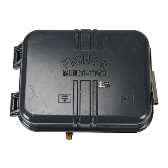
Figure 1. Type 2506 Multi-Trol
12
12
12
12
13
13
13
14
15
15
16
16
17
17
17
17
W4688 / IL
18
19
19
19
Figure 2. Type 2516 Multi-Trol
R
Receiver-Controller
R
Receiver-Controller
Advertisement
Table of Contents

Related Manuals for Fisher 2506


Summary of Contents for Fisher 2506
-
Page 1: Table Of Contents
........Figure 1. Type 2506 Multi-Trol Receiver-Controller Adjustments . -
Page 2: Introduction
Changing this A 2506 Series receiver/controller is often used with a adjustment changes the position of the nozzle in ® relationship to the beam/flapper assembly. In turn, 2502 Series Level-Trol controller/transmitter. -
Page 3: See Table
(S) control or for either direct or reverse (R) action Performance Type 2516: A Type 2506 that also provides Hysteresis: 0.6 percent of output pressure proportional-plus-reset control change at 100 percent of proportional band for... -
Page 4: Educational Services
7 scfh 42 scfh 1. Consult your Fisher sales office for gauges calibrated in other units of measurement. 2. Control and stability may be impaired if this pressure is exceeded. 3. At zero or maximum proportional band or span setting. -
Page 5: Mounting The Controller
Instruction Manual Form 1041 2506 Series Receiver/Controllers November 2005 MOUNTING (9.25) (2.75) (2.75) HOLES (2 PLACES) 5/16-18 UNC (2.25) TAPPED VENT FOR VENT LINE (1.75) (OPTIONAL) (6.76) (1.62) BELLOWS VENT OR REMOTE (9.12) SET POINT CONNECTION INSTRUMENT CONNECTION OUTPUT CONNECTION... -
Page 6: Actuator Diaphragm Case Mounting
(KEY 78) (KEY 164) To mount a receiver/controller to the diaphragm casing of a standard Fisher diaphragm actuator, remove two hex nuts and hex head cap screws securing the upper and lower diaphragm casings. If necessary, refer to the appropriate actuator... -
Page 7: Pipestand Mounting
CAP SCREW 3. Locate the receiver/controller mounting position LOCKWASHER on the horizontal edge of the diaphragm case. A (KEYS 39 typical Fisher diaphragm actuator features upper AND 83) and lower diaphragm casings held together with hex PIPE CLAMP head cap screws and hex nuts. Remove the hex... -
Page 8: Connections
FRONT VIEW 3V7594-B B2115-1 / IL Figure 9. 2500 Series Controller-Transmitter and 2506 Series Receiver-Controller Mounting 1. Install lock washers (key 83) on the cap screws exceeds the maximum safe working (key 39). Then, insert the cap screws through the pressure of any connected equipment. -
Page 9: Output Connections
40 damage, provide pressure-relieving or microns in diameter will suffice in pressure-limiting devices if supply or most applications, check with a Fisher input pressure could exceed the Field office and Industry Instrument air maximum allowable pressures listed in quality standards for use with table 3. -
Page 10: Instrument Connection
Instruction Manual Form 1041 2506 Series Receiver/Controllers November 2005 INDICATOR CONTROLLER/ 2500 SERIES TRANSMITTER CONTROLLER/ SUPPLY TRANSMITTER SUPPLY PANEL LOADER REMOTE SET POINT ADJUSTMENT CENTRALIZED CONTROL PANEL CONTROLLER OUTPUT PIPING 2506 SERIES REMOTE RECEIVER/CONTROLLER DIAPHRAGM ACTUATOR RECEIVER/ CONTROLLER SUPPLY CONTROL VALVE... -
Page 11: Remote Set Point Connection
D To make the proper level or output pressure remove particles larger than 40 setting for a Type 2506 receiver/controller, go to microns in diameter will suffice in step 3. To make the proper level or output... -
Page 12: Adjustments
Instruction Manual Form 1041 2506 Series Receiver/Controllers November 2005 Adjustments output pressure change. Operate the receiver/controller with the proportional band setting To adjust the receiver/controller, open the cover and as small as possible. locate the appropriate adjustment. See figures 14, 4. -
Page 13: Reset Adjustment (Type 2516 Receiver/Controller Only)
(Type 2516F Receiver/Controller Only) controller arrangement such as the The anti-reset windup valve provides differential Type 2500 with the Type 2506 or 2516 pressure relief. Its adjustment control extends from (figure 9), calibrate the Type 2500 the back of the receiver/controller case (figure 16). -
Page 14: Principle Of Operation
0.2 to 1 bar (3 to 15 psig) or 2 bar (30 psig) for a 0.4 to 2 bar (6 to 30 psig) receiver/controller. The 2506 Series uses a basic pressure balance relay system (figure 12). The relay is connected so 9. -
Page 15: Type 2506 Receiver/Controllers
Instruction Manual Form 1041 2506 Series Receiver/Controllers November 2005 TRANSMITTER INPUT REVERSING SWITCH REMOTE SETPOINT BELLOWS BELLOWS VENT OR REMOTE SETPOINT CONNECTION RESET RELIEF PROPORTIONAL BELLOWS VALVE SPRING BEAM/FLAPPER ADJUSTING ASSEMBLY SCREW RESET SENSING BELLOWS BELLOWS BEAM/ FLAPPER ASSEMBLY RESTRICTION... -
Page 16: Maintenance
Establish a maintenance cycle to regularly clean the either direct or reverse action. The vents (figure 3). Also, establish a maintenance cycle receiver/controller (Type 2506 or 2516) can be to clear the relay orifice (key 88, not shown) by changed between direct and reverse action by pushing in the plunger of the core assembly (key repositioning the switch plate (key 132) on the left. -
Page 17: Troubleshooting
PROPORTIONAL BAND position the switch plate so the P is visible. For Type adjustment assembly. 2506 receiver/controllers, to obtain snap action, position the switch plate so the S is visible. Replacing Receiver/Controller Parts See figure 14 for key number locations, unless Troubleshooting otherwise indicated. -
Page 18: Changing The Relay
Instruction Manual Form 1041 2506 Series Receiver/Controllers November 2005 Table 4.Troubleshooting Chart Fault Possible Cause Check Correction 1. Process wanders or cycles 1.1 Proportional band or specific 1.1 Insure that the prestartup 1.1 If stable control cannot be around setpoint. -
Page 19: Changing Proportional Or Reset Valve
Additional option: Case pressure-tested responsibility for the selection, use, to 0.1 bar (2 psig). Contact your Fisher sales office to order pressure testing. and maintenance of any product. Label (key 179) is added to the case. 2E355544012... - Page 20 1K674838072 Machine screw, stainless steel (4 req’d) 1C899028982 Relay tubing assembly, Spring (not shown) 1J423437022 Type 2506 and 2516, stainless steel 1K674738072 Bellows stud, brass (2 req’d) (not shown) 1D397814012 Orifice cap, brass 0X0843X0012 Bellows beam, steel pl...
- Page 21 2506 Series Receiver/Controllers November 2005 30A8956-B TYPE 2506 SETPOINT ADJUSTMENT USE W/THREADED CASE VENT RESET VALVE ADJUSTMENT PROPORTIONAL BAND VALVE VIEW A ADJUSTMENT WITH SWITCH PLATE REMOVED TYPE 2516 C0670-2 / IL Figure 14. Types 2506 and 2516 Receiver-Controller Assemblies...
- Page 22 Instruction Manual Form 1041 2506 Series Receiver/Controllers November 2005 Description Part Number Bellows screw (4 req’d) brass 1D3976X0012 stainless steel 1D3976X0022 External vent assembly (not shown) for bellows vent opening when remote set point connection is not made plastic/stainless steel...
- Page 23 Instruction Manual Form 1041 2506 Series Receiver/Controllers November 2005 RESET VALVE ADJUSTMENT RECEIVER/ CONTROLLER BACK 15A7608-B A3841 / IL ANTI-RESET WINDUP ADJUSTMENT Figure 16. Type 2516F Reset and Anti-Reset Windup Valve Assembly Description Part Number Description Part Number Mounting Parts...
- Page 24 Multi-Trol, Level-Trol and Fisher are marks owned by Fisher Controls International LLC, a member of the Emerson Process Management business division of Emerson Electric Co. Emerson and the Emerson logo are trademarks and service marks of Emerson Electric Co. All other marks are the property of their respective owners.
Need help?
Do you have a question about the 2506 and is the answer not in the manual?
Questions and answers