Table of Contents
Advertisement
Quick Links
Instruction Manual
Form 1041
September 1993
2506 Series Multi-Trol Receiver/Controllers
(Types 2506, 2516, 2516F)
Contents
. . . . . . . . . . . . . . . . . . . . . . . . . . . . . . .
. . . . . . . . . . . . . . . . . . . . . . . . . . . . .
. . . . . . . . . . . . . . . . . . . . . . . . . . . . . . . . . .
. . . . . . . . . . . . . . . . . . . . . . . . . . . . . . .
. . . . . . . . . . . . . . . . . . . . . . . . . . . . . . .
. . . . . . . . . . . . . . . . . . . . . . . . . .
. . . . . . . . . . . . . . . . . . . . . . . . . . . . . .
. . . . . . . . . . . . . . . . . . . . . . . . . . .
. . . . . . . . . . . . . . . . . . . . . . . . . .
. . . . . . . . . . . . . . . . . . . . . . . . . . . . . . . . . . . . . . .
. . . . . . . . . . . . . . . . . . . . . . . . . . . . . . . . . . .
. . . . . . . . . . . . . . . . . . . . . . . . . . . . .
. . . . . . . . . . . . . . . . . . . . . . . . . . . . . . .
. . . . . . . . . . . . . . . . .
. . . . . . . . . . . . . . . . . . . . . .
. . . . . . . . . . . .
. . . .
. . . . . . . . . . . . . . . . . . . . . . . .
. . . . . . . . . . . . . . . . .
. . . . . . . . . . . . . . . . . . . . . . .
. . . . . . . . . . . . . . .
. . . . . . . . . . . . . . .
. . . . . .
. . . . .
. . . . . . . . . . . . . . . . . .
. . . . . . . . . . . . . .
. . . . . .
Types 2506, 2516, 2516F
2
2
2
2
2
4
4
5
6
6
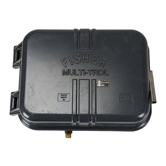
W4687 / IL
6
Figure 1. T ype 2506 Multi-T rol Receiver-Controller
7
8
8
8
9
10
10
10
10
11
11
11
11
12
W4688 / IL
12
Figure 2. T ype 2516 Multi-T rol Receiver-Controller
13
Advertisement
Table of Contents

Subscribe to Our Youtube Channel
Related Manuals for Fisher 2506


Summary of Contents for Fisher 2506
-
Page 1: Table Of Contents
......Figure 1. T ype 2506 Multi-T rol Receiver-Controller Supply Connection . -
Page 2: Introduction
Receiver/Controller Common Parts ... When a Type 2506 receiver/controller is used to pro- Relay Assembly ...... - Page 3 (S) control or for either direct or reverse (R) action Steady State Air Consumption Type 2516: A Type 2506 that also provides propor- See table 3 tional-plus-reset control Type 2516F: A Type 2516 that also provides anti-...
-
Page 4: Actuator Yoke Mounting
0 to 60 psig 7 scfh 42 scfh 1. Consult your Fisher Controls sales office or representative for gauges calibrated in 4. At setting in middle of proportional band or span range. other units of measurement. 5. If air consumption is desired in normal m /hr at 0 C and 1.01325 bar, multiply scfh... -
Page 5: Actuator Diaphragm Case Mounting
To mount a receiver/controller to the diaphragm casing from two hex head cap screws joining the upper and of a standard Fisher Controls diaphragm actuator, re- lower casing. Then, remove the cap screws. move two hex nuts and hex head cap screws securing the upper and lower diaphragm casings. -
Page 6: Pipestand Mounting
Types 2506, 2516, 2516F Add the nuts and tighten to secure the mounting bracket with receiver/controller to the casing. 5. If supply pressure is piped through a filter/regulator, the regulator may be attached in one of two locations: Attach the regulator directly to the upper yoke boss using the cap screws (key 85) for yoke mounting. -
Page 7: Supply Connection
Types 2506, 2516, 2516F AR5748-B 3V7594-A B2115-1 / IL Figure 9. 2500 Series Controller -T ransmitter and 2506 Series Receiver -Controller Mounting To complete the installation of a receiver/controller, or filter regulator capable of removing make connections with tubing and fittings between the particles 40 microns in diameter should receiver/controller and the actuator. -
Page 8: Output Connections
Types 2506, 2516, 2516F DF5357-A A3701-2 / IL Figure 10. T ypical Transmitter with Receiver and Control V alve Installation Assembly Output Connections or property damage could also result from contact with the flammable, toxic, See figure 3. corrosive, or reactive gas. -
Page 9: Remote Set Point Connection
Types 2506, 2516, 2516F DF5379-A A3702-2 / IL Figure 1 1. T ypical T ransmitter and Receiver Installation with an Indicator and Remote Set Point Connection Optional, with tapped vent, for applications re- Remote Set Point Connection quiring vent line attachment to receiver/controller case. -
Page 10: Startup
Adjustments To make the proper level or output pressure setting for a Type 2506 receiver/controller, go to To adjust the receiver/controller, open the cover and step 3. To make the proper level or output pres- locate the appropriate adjustment. See figures 15, 18, sure setting for a Type 2516 receiver/controller, go 19 for the location of adjustments. -
Page 11: Proportional Band Adjustment
Types 2506, 2516, 2516F Proportional Band Adjustment To adjust the reset action, rotate the adjustment clock- wise to decrease, or counterclockwise to increase the For proportional and proportional-plus-reset receiver/ minutes per repeat. Increasing the minutes per repeat controllers, the proportional band adjustment deter- provides a slower reset action. -
Page 12: Principle Of Operation
A3849 / IL 30 psig (0.4 to 2 bar) receiver/controller. 5. For Type 2516 only, turn the reset valve adjust- Figure 12. T ype 2506 Multi-T rol Direct Action ment fully counterclockwise (to the CLOSED position). Receiver/Controller Schematic This locks 9 psig (0.6 bar) or 18 psig (1.2 bar) in the reset bellows. -
Page 13: Types 2516, 2516F Receiver/Controllers
Types 2506, 2516, 2516F B2116 / IL Figure 13. T ype 2516 and 2516F Multi-T rol Direct Action Receiver-Controller Schematic ters the relay through the fixed restriction. A change in Users can adjust the reset valve on the Type 2516... -
Page 14: Maintenance
WITHIN 0.005 INCHES (0.1) INCH 15A3519-B (mm) Due to the care Fisher Controls takes in meeting all A5871 / IL manufacturing requirements (For example: heat treat- ing, dimensional tolerances, and other manufacturing Figure 14. Relay Alignment T ool (Part Number 15A3519 X012) specifications), use only genuine replacement parts manufactured or furnished by Fisher Controls. -
Page 15: Troubleshooting
1/8-inch NPT pipe plug according to lers, to obtain proportional action, position the switch the sections for changing proportional, reset, or anti- plate so the P is visible. For Type 2506 receiver/con- trollers, to obtain snap action, position the switch plate reset windup valves. -
Page 16: Replacing Receiver/Controller Parts
Types 2506, 2516, 2516F output pressure change just begins. Record the value 3. Secure the screws (key 96) and replace the tubing. of the process variable at this detection point. 4. Check all tubing connections and the bellows screws for leaks. Tighten as necessary and proceed to 4. -
Page 17: Changing Proportional Or Reset Valve
Whenever corresponding with the Fisher Controls lined up. For a high temperature relay, also install a sales office or representative, include the receiver/con- gasket over the top diaphragm. -
Page 18: Parts List
1K674838072 Type 2516F Note Copper 1D3984000A2 Bellows Assembly Relay tubing assembly, Type 2506, 2516, and 2616F, copper 1H2744000A2 Select specific bellows assembly by application pres- Type 2506 and 2516, stainless steel 1K674738072 sure range. * Recommended spare part. 1. Trademark of Metalimphy, Inc. - Page 19 Types 2506, 2516, 2516F 30A8956-B C0670-2 / IL Figure 15. T ypes 2506 and 2516 Receiver -Controller Assemblies...
-
Page 20: Relay Assembly
Types 2506, 2516, 2516F Description Part Number Bellows assembly Brass Range: 3 to 15 psig (0.2 to 1 bar) Gray color code 14A5726X072 6 to 30 psig (0.4 to 2 bar) Green color code 14A5726X082 Stainless steel Range: 3 to 15 psig (0.2 to 1 bar) - Page 21 Types 2506, 2516, 2516F Figure 17. T ypical Relay Assembly 22B0462-A / DOC Description Part Number Diaphragm assembly Standard temperature, nitrile/nylon 18A2451X012 High temperature, polyacrylate/nylon 18A2451X092 Inner valve, brass 1H825114012 Orifice assembly, brass 12B0468X012 O-Ring (2 req’d) Standard temperature, nitrile...
-
Page 22: Anti-Reset Windup Valve For Type 2516F Only
Types 2506, 2516, 2516F 15A7608-B A3841 / IL Figure 19. T ype 2516F Reset and Anti-Reset Windup V alve Assembly Description Part Number Description Part Number Anti-Reset Windup Valve for Mounting Parts Type 2516F Only (figure 18) Yoke Mounting (figures 3, 4) -
Page 23: Case Mounting
1A368324052 Cap screw (2 req’d) 1C631224052 Mounting bracket, steel pl 1F401225072 Regulator mounting on Types 2506, 2516. W/separate supply sources and separate regulators Regulator mounting. To actuator case (not shown) Hex nut (2 req’d) 1E944024112 Nipple, to join regulator to receiver/controller Lock washer (2 req’d) - Page 24 Types 2506, 2516, 2516F Multi-Trol, Level-Trol, Fisher, Fisher-Rosemount, and Managing The Process Better are marks owned by Fisher Controls International, Inc. or Fisher-Rosemount Systems, Inc. All other marks are the property of their respective owners. Fisher Controls International, Inc. 1978, 1993; All Rights Reserved...
Need help?
Do you have a question about the 2506 and is the answer not in the manual?
Questions and answers