Table of Contents
Advertisement
INSTALLER/CONSUMER
SAFETY INFORMATION
PLEASE READ THIS MANUAL
BEFORE INSTALLING AND
USING APPLIANCE
WARNING!
IF THE INFORMATION IN THIS
MANUAL IS NOT FOLLOWED
EXACTLY, A FIRE OR
EXPLOSION MAY RESULT
CAUSING PROPERTY
DAMAGE, PERSONAL INJURY
OR LOSS OF LIFE.
FOR YOUR SAFETY
Installation and service must
be performed by a qualified
installer, service agency or
the gas supplier.
WHAT TO DO IF YOU SMELL GAS:
•
Do not try to light any appliance.
•
Do not touch any electric switch;
do not use any phone in your
building.
•
Immediately call your gas
supplier from your neighbor's
phone. Follow the gas suppliers
instructions.
•
If you cannot reach your gas
supplier call the fire department.
DO NOT STORE
OR USE GASOLINE OR
OTHER FLAMMABLE VAPORS
AND LIQUIDS IN THE VICINITY
OF THIS OR ANY OTHER
APPLIANCE.
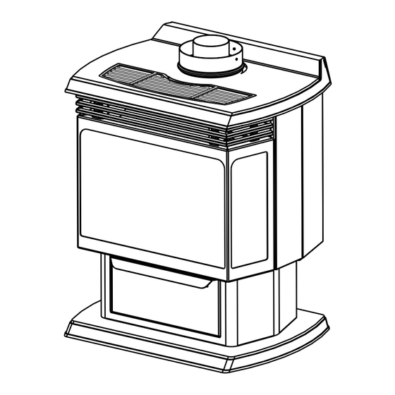
Freestanding Direct
Vent Gas Stove
Models:
RFSDV24, RFSDV34
RFSDV_24_34_line
1_3550
Installation Instructions and
rev. 0602 rjs
Homeowner's Manual
INSTALLER: Leave this manual with the appliance.
CONSUMER: Retain this manual for future reference.
10003550 2/10 Rev. 10
Advertisement
Table of Contents
Troubleshooting

Subscribe to Our Youtube Channel
Related Manuals for MHSC RFSDV24


Summary of Contents for MHSC RFSDV24
- Page 1 Freestanding Direct Vent Gas Stove Models: RFSDV24, RFSDV34 INSTALLER/CONSUMER SAFETY INFORMATION PLEASE READ THIS MANUAL BEFORE INSTALLING AND USING APPLIANCE WARNING! IF THE INFORMATION IN THIS MANUAL IS NOT FOLLOWED EXACTLY, A FIRE OR EXPLOSION MAY RESULT CAUSING PROPERTY DAMAGE, PERSONAL INJURY OR LOSS OF LIFE.
-
Page 2: Table Of Contents
Table of Contents PLEASE READ THE INSTALLATION & OPERATING INSTRUCTIONS BEFORE USING THIS APPLIANCE. Thank you and congratulations on your purchase of an MHSC gas stove. IMPORTANT: Read all instructions and warnings carefully before starting installation. Failure to follow these instructions may result in a possible fire hazard and will void the warranty. -
Page 3: Installation & Operating Instructions
RFSDV24/34 Freestanding Direct Vent Gas Stove Installation & Operating Instructions This gas stove should be installed by a qualified installer in 12. This unit requires adequate ventilation and combustion air to accordance with local building codes and with current CSA- operate properly. -
Page 4: Requirements For The Commonwealth Of Massachusetts
RFSDV24/34 Freestanding Direct Vent Gas Stove Installation & Operating Instructions Inspection Requirements for the Commonwealth of Massachusetts The state or local gas inspector of the side wall horizontally vented gas fueled equipment shall not All gas fitting and installation of this heater shall only be approve the installation unless, upon inspection, the done by a licensed gas fitter or licensed plumber. -
Page 5: Unit Dimensions
RFSDV24/34 Freestanding Direct Vent Gas Stove Stove Dimensions Fig. 1 Stove specifications and framing dimensions. 3550 Ref. RFSDV24 RFSDV34 RFSDV34 dims 23” (584 mm) 26Z\v” (667 mm) 28C\v” (730 mm) 31Z\x” (800 mm) 16B\,” (422 mm) 19C\,” (492 mm) 27C\,”... -
Page 6: Locating Your Stove
RFSDV24/34 Freestanding Direct Vent Gas Stove Locating Your Stove Gas Specifications 12” Max. Min. (305 mm) Input Input Model Fuel Gas Control BTU/h BTU/h RFSDV24SRN Millivolt Manual 20,000 14,000 12” (305 mm) RFSDV24SRP Prop Millivolt Manual 20,000 15,000 RFSDV34TSRN Millivolt Hi/Lo... -
Page 7: Remote Switch Installation
RFSDV24/34 Freestanding Direct Vent Gas Stove 1/2” Gas Supply Screw 1/2” x 3/8” Reducer (through existing ON/OFF Switch hole) Assembly Screw 3/8” Nipple Clips 3/8” Union 3/8” Nipple 3/8” x 3/8” Shut-Off Valve CFM106 3/8” Nipple Wiring for Fig. 3 Typical gas line connection. -
Page 8: General Venting Information-Termination Location
2. The special venting system used on Direct Vent Stoves are certified as part of the appliance, with clearances tested and approved by the listing agency. 3. MHSC assumes no responsibility for the improper performance of the appliance when the venting system does not meet these requirements. -
Page 9: General Information On Assembling Vent Pipes
Direct Vent systems. of the twist lock pipe prior to assembly. Twist Lock Pipes When using MHSC twist-lock pipe it is not necessary to Female End Male End use sealant on the joints. The only areas of the venting... -
Page 10: How To Use The Vent Graph
• The maximum number of 90° elbows per side wall installations is three (3). • For RFSDV24 and RFSDV34 models, the maximum horizontal rn for a minimum 12” (305 mm) vertical rise is 3’ (914 mm). (Fig. 9) 36” (914 mm) - Page 11 RFSDV24/34 Freestanding Direct Vent Gas Stove Example: Elbow 1 = 90° Elbow 2 = 45° Elbow 3 = 45° Elbow 4 = 90° Total angular variation = 270° 7.5ʼ (2286 mm) 1 + 2 + 3 + 4 = 270°...
- Page 12 RFSDV24/34 Freestanding Direct Vent Gas Stove STEP 2 Bead of Sealant Measure wall thickness and cut zero clearance sleeve parts to proper length (MAXIMUM 12”/305 mm). As- semble sleeve and attach to firestop with #8 sheet metal screws (supplied). Install firestop assembly. (Fig.
-
Page 13: Below Grade Installations
RFSDV24/34 Freestanding Direct Vent Gas Stove Below Grade Installations When it is not possible to meet the required vent ter- minal clearances of 12” (305 mm) above grade level a snorkel vent kit is recommended. It allows installation depth of down to 7” (178 mm) below grade level. The 7”... -
Page 14: Vertical Through-The-Roof Applications & Installations
RFSDV24/34 Freestanding Direct Vent Gas Stove Do not back fill around snorkel. A clear- ance of at least 4” (102 mm) must be main- tained between snorkel and the soil. Max. If the foundation is recessed, use recess brackets (not 8’... - Page 15 RFSDV24/34 Freestanding Direct Vent Gas Stove If there is a room above ceiling level, Vertical Through-the-Roof Installation firestop spacer must be installed on both 1. Locate your stove. the bottom and the top side of the ceiling joists. If an attic is above ceiling level a 2.
-
Page 16: Venting Components
RFSDV24/34 Freestanding Direct Vent Gas Stove Twist Lock Venting Components Starter Kit - Model 7TFSMSK Starter Kit - Model 7TFSDVSK Starter Kit - Model 7TDVSKV - Vertical Venting for 7TDVSKV-A, order 1/12 to 6/12 roof pitch for 7TDVSKV-B, order 7/12 to 12/12 roof pitch... -
Page 17: Operating Instructions
After the initial cleaning process the glass should be Glass Information cleaned two or three times during each operating Only glass approved by MHSC may be used for season depending on the environment in the house. replacement. The use of substitute glass will void Clean the glass after the first two weeks of all product warranties. - Page 18 RFSDV24/34 Freestanding Direct Vent Gas Stove For Model RFSDV34 (Refer to Fig. 28) Figure 27 Log Rear Left (KR15) RFSDV24 1. Remove window frame assembly. (Refer to Window Frame Assembly Log Rear Right (KR16) Removal section) 2. Remove logs from packaging.
-
Page 19: Flame & Temperature Adjustment
RFSDV24/34 Freestanding Direct Vent Gas Stove Flame & Temperature Adjustment Flame Characteristics It is important to periodically perform a visual check SRN/SRP Models of the pilot and burner flames. Compare them to the For units equipped with ‘HI/LO’ valves the flame pictorials illustrated below (Fig. -
Page 20: Lighting & Operating Instructions
RFSDV24/34 Freestanding Direct Vent Gas Stove Lighting and Operating Instructions FOR YOUR SAFETY READ BEFORE LIGHTING WARNING: If you do not follow these instructions exactly, a fire or explosion may result causing property damage, personal injury or loss of life. -
Page 21: Troubleshooting Nova Sit 820 Millivolt Valve
RFSDV24/34 Freestanding Direct Vent Gas Stove Troubleshooting the Gas Control System SIT NOVA 820 MILLIVOLT VALVE NOTE: Before trouble shooting the gas control system, be sure external gas shut off is in the “On” position. Possible Causes Symptom Corrective Action 1. -
Page 22: Instructions For Rcsite
RFSDV24/34 Freestanding Direct Vent Gas Stove Instructions for RCSITEA 2. Slide the privacy code switches (1,2,3 & 4) on the transmitter and receiver to your choice of ON or OFF RFSDV34TSR Series position. All switches are preset to “ON” for both the CAUTION: The RCSITE is only certified for use on transmitter and receiver. -
Page 23: Thermostatic Mode
RFSDV24/34 Freestanding Direct Vent Gas Stove The transmitter will operate the remote receiver from 1 off the fireplace when the room temperature is above foot to a maximum of 30 feet. The distance is reduce the set temperature within 1 degree. - Page 24 RFSDV24/34 Freestanding Direct Vent Gas Stove Blower On Delay Time and OFF Delay Time Set- the ON and OFF buttons simultaneously for three (3) seconds to exit child proof mode. The Childproof ting (Default 5 ON / 8 OFF) indicator disappears from LCD.
- Page 25 RFSDV24/34 Freestanding Direct Vent Gas Stove Testing Remote Control System Blower Speed Level Adjustment 1. Light the gas appliance following the lighting instruc- 1. The three speed levels of blower can be fine tuned tions on Page xx. Confirm the pilot light is on; it must by using the blower switches.
-
Page 26: Troubleshooting
RFSDV24/34 Freestanding Direct Vent Gas Stove Troubleshooting Action Symptom Causes 1. Replace batteries. Change the bat- 1. Battery icon on LCD on transmit- 1. Low battery. teries every 6 months. ter. 2. LCD display is blank. 2. Check battery installation or replace batteries. -
Page 27: Maintenance
RFSDV24/34 Freestanding Direct Vent Gas Stove Maintenance Burner and Burner Compartment To obtain proper operation, it is imperative that the pilot and burner’s flame characteristics are steady, not lifting It is important to keep the burner and the burner or floating. -
Page 28: Wiring Diagrams
RFSDV24/34 Freestanding Direct Vent Gas Stove Wiring Diagrams - RFSDV24SR Optional Blower Kit MOTOR Schematic Diagram On/Off Switch Wiring SNAPSTAT TP/TH Millivolt Gas Valve ON/OFF Black RHEOSTAT ST124b Thermostat Thermostat (Optional) Optional Thermostat (Optional) ST236 Wiring Fig. 46 Fan circuit. - Page 29 RFSDV24/34 Freestanding Direct Vent Gas Stove Wiring Diagrams - RFSDV34TSR Black 120V AC Adapter Black T H mV Valve Receiver T P / T H 120V AC Plug Female Male SIT HI / LO 120V AC Valve Blower ST1091 Fig. 47 SIT Hi/Lo blower schematic.
-
Page 30: Replacement Parts
1h 1d 1b 1b 1c 1b 34 1a 9a,b MHSC reserves the right to make changes in design, materials, specifications, prices and discontinue colors and products at any time, without notice. RFSDV24/34 3550 RFSDV24/34 Ref. Description RFSDV24 RFSDV34 Parts 1. Log Set Complete... - Page 31 RFSDV24/34 Freestanding Direct Vent Gas Stove RFSDV24/34 (continued) Ref. Description RFSDV24 RFSDV34 1f. Log - Top Right KR12 1g. Log - Rear Left KR15 1h. Log - Rear Right KR16 2. Lava Rock 57897 57897 3. Burner Housing Assembly w/tiles...
- Page 32 RFSDV24/34 Freestanding Direct Vent Gas Stove RFSDV24/34 (continued) Fuel Conversion Kits Conversion Kit, NG to LP - RFSDV24SR Kit #RFSDV24CKPS Conversion Kit, NG to LP - RFSDV34TSR Kit #RFSDV34CKPS Conversion Kit, LP to NG - RFSDV24SR Kit #RFSDV24CKNS Conversion Kit, LP to NG - RFSDV34TSR...
-
Page 33: Optional Accessories
Check the fan and the area around the fan assembly and wipe or vacuum at least once per month during the operating season. Installation NOTE: The FK24 is an option for Model RFSDV24; standard with model RFSDV34. Install fan before FP1518 connecting gas line to stove. -
Page 34: Optional Gold Trim Kit
1. Unpack the kit and confirm all parts are present. A decorative gold-plated window trim kit, Model RFS- 2. It is very important to remove all the protective plas- DV24DG is available for the RFSDV24 Freestanding tic wrap from the brass components Stove. -
Page 35: Warranty
(2) years from date of installation. After installation, if any of the components manufactured by MHSC in the appliance are found to be defective in materials or workmanship, MHSC will, at its option, replace or repair the defective components at no charge to the original owner. -
Page 36: Energuide
RFSDV24/34 Freestanding Direct Vent Gas Stove Efficiency Ratings Model EnerGuide Ratings D.O.E. Stove Efficiency (%) (AFUE %) RFSDV24SRN 65.3 63.0 RFSDV24SRP 65.3 63.0 RFSDV34TSRN 72.1 70.0 RFSDV34TSRP 72.1 70.0 MHSC 149 Cleveland Drive • Paris, Kentucky 40361 www.mhsc.com 10003550...
Need help?
Do you have a question about the RFSDV24 and is the answer not in the manual?
Questions and answers