Table of Contents
Advertisement
Quick Links
Advertisement
Table of Contents

Related Manuals for Nuvico EV-8000


Summary of Contents for Nuvico EV-8000
-
Page 2: Content Verification
CONTENT VERIFICATION Before installing the DVR, please make sure that the following items are included in the box: 1. Digital Video Recorder 2. Remote Controller 3. DVR Client Software CD 4. Power Adapter 5. Two AAA Batteries 6. This Instruction Manual If any of these materials are missing, please contact your vendor. -
Page 3: Disclaimer
DISCLAIMER • While every effort has been made to ensure that the information contained in this guide is accurate and complete, no liability can be accepted for any errors or omissions. • We reserve the right to change the specifications of the hardware and software described herein at any time without prior notice. -
Page 4: Fcc Notice
FCC NOTICE Digital Video Recorder, Model MPEG4, 8 & 16-channel. This device complies with Part 15 of the FCC Rules. Operation is subject to the following two conditions; 1. This device may not cause harmful interference, and 2. This device must accept any interference received, including interference that may cause undesired operation. -
Page 5: Read This First
READ THIS FIRST TEST SESSIONS Before you try to record important subjects, we highly recommend that you make several test recording and playback sessions to ensure that the Digital Video Recorder is operating and being operated correctly. Please note that the manufacturer, its subsidiaries and affiliates, and its distributors are not liable for any consequential damages arising from any malfunction of a Digital Video Recorder or its accessory, including the hard disk drive, which results in the failure of an image to be recorded or to be recorded in a format that is machine sensible. -
Page 6: Safety Precautions
SAFETY PRECAUTIONS 1. Before using the Digital Video Recorder, please ensure that you read and understand the safety precautions described below. Always ensure that the Digital Video Recorder is operated correctly. 2. The safety precautions noted on the following pages are intended to instruct you in the safe and correct operation of the DVR and its accessories to prevent injuries or damage to the self, other persons and equipment. -
Page 7: Caution
14. Do not short-circuit the battery terminals with metallic objects, such as key holders. It could lead to overheating, burns and other injuries. 15. The supplied power supply and power cord are designed for exclusive use with the Digital Video Recorder. -
Page 8: Table Of Contents
TABLE OF CONTENTS CONTENT VERIFICATION..................1 DISCLAIMER......................2 FCC NOTICE ......................3 CANADIAN RADIO INTERFERENCE REGULATIONS..........3 READ THIS FIRST..................... 4 TEST SESSIONS............................ 4 THE PRIVACY ACT OF 1974(5 U.S.C. § 552a) ..................4 WARRANTY LIMITATIONS ........................4 SAFETY PRECAUTIONS ..................5 WARNING........................ - Page 9 IV. SETUP........................ 42 1. DISPLAY............................43 1.1 DISPLAY SETUP ................................43 1.1.1 STATUS BAR ............................... 43 1.1.2 CAMERA ................................43 1.1.3 BORDER LINE ..............................44 1.1.4 BACKGROUND..............................44 1.1.5 DISPLAY DEVICE ..............................44 1.2 SEQUENTIAL SETUP..............................45 1.2.1 SEQUENCE INTERVAL ............................45 1.2.2 SEQUENCE MODE ..............................
- Page 10 8.1 GENERAL..................................73 8.1.1 SYSTEM ID................................73 8.1.2 AUTO KEY LOOCK.............................. 73 8.1.3 KEY TONE................................74 8.1.4 KEYPAD MODEL ..............................74 8.1.5 RECORD SIZE..............................74 8.2 TIME ..................................... 75 8.2.1 TIME SYNC................................75 8.2.2 TIME SERVER..............................75 8.2.3 DATE ..................................75 8.2.4 TIME ..................................
-
Page 11: Quick Start Page
QUICK START PAGE The Factory Default password for the unit is “000000” SECURITY WARNING Please be sure to change the administrator and user’s password from the unit. Please refer to page - 10 -... -
Page 12: Digital Video Recorder Layout
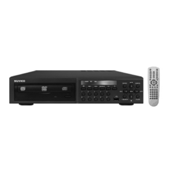
DIGITAL VIDEO RECORDER LAYOUT 1. FRONT PANEL LAYOUT 1. DVD/RW DVD/RW Drive is used to backup video files. 2. STATUS INDICATOR Three LEDs display the status of the DVR. From the left, Power, Recording, HDD. 3. NUMERIC BUTTONS (1~0) These buttons have a number of functions to enter data and to make selections. They are used to enter numerical data when prompted for the password, to make channel/camera selection, to choose the day in schedule option, and to enter alphabets to label each channel. - Page 13 12. + / LOG This button is used to select options from various menus. It is also used to access the Log screen. 13. RIGHT / FAST FORWARD This button is used to navigate right in some menus. It is also used to fast forward during the playback.
-
Page 14: Rear Panel Layout
2. REAR PANEL LAYOUT 1. CAMERA INPUTS BNC connectors for composite video inputs. 2. VIDEO OUT BNC connector for composite main/video output. 3. SPOT OUT BNC connector for spot monitor output. 4. VGA OUTPUT RGB connector for main VGA output. 5. - Page 15 12. AUDIO INPUT RCA connectors for audio inputs. 13. AUDIO OUTPUT RCA connector for audio output to a speaker. - 14 -...
-
Page 16: Ir Remote Controller
3. IR REMOTE CONTROLLER POWER DVR ID EXT. SEARCH TIME SEARCH INFORMATION BACK UP DISPLAY MODE PAN/TILT/ZOOM ENTER CANCEL / OSD OFF ZOOM MENU - BUTTON REWIND + BUTTON STOP FAST FORWARD SCHEDULE REC ON/OFF PLAY RECORD STEP NUMBERS & ALPHABET - 15 -... -
Page 17: Basic Settings
I. BASIC SETTINGS TIME & DATE SETTING When the DVR is powered on for the very first time, the time and date are set as default to January 1, 2006 Sunday 00:00:00. Before any other operation of the Digital Video Recorder, it is important to setup the time and the date as shown below. -
Page 18: Basic Operation
II. BASIC OPERATION This section will cover basic features of the DVR such as simple recording and playback. Also, it will cover the main screen explaining many alert, operational, channel, DVR status, the time and hard drive space counter. Moreover, it will also address live view mode that the DVR has to offer. Which include automatic sequence mode and digital zoom feature. -
Page 19: Live View
2. LIVE VIEW The live view displays each channel at 30 frames per second. 2.1 AUTOMATIC SEQUENCE Please refer to page 45 for selecting and activating the automatic sequence modes. Press the display button and hold onto to it for 1 second to activate the sequence mode. Pressing the display mode will change the display mode to the single channel display initially, and continue to sequence through all the channels in full screen mode. -
Page 20: Spot Out
Press the Enter button once more to zoom into the selected area on the screen. Use the directional buttons to move the zoomed window around the screen. Pressing + again will zoom in into 4x the mode, and once again to zoom in into the 8x mode. Press Enter button and Press – button to zoom out to 4x mode and again to 2x mode. -
Page 21: Log
3. LOG The log chart keeps record of all the events and alerts, 8 logs per page. The DVR keeps log from the initial power on of the DVR. The record of items are compiled and listed in five categories. 3.1 ALL All events related to the operation and alerts of the DVR are listed and sorted under ALL, in chronological order,... -
Page 22: Network
3.3 NETWORK Any network activity is listed and sorted under NETWORK in the same chronological order. 3.4 ALARM Any alarm activity is listed and sorted under ALARM in the same chronological order. 3.5 MOTION Any motion activity is listed and sorted under MOTION in the same chronological order. -
Page 23: Basic Recording
4. BASIC RECORDING The DVR comes with a certain preset settings from the factory. Therefore, once the DVR is installed, immediate recording is possible after pressing the record button. The DVR differentiates normal recording, alarm recording and schedule recording. Normal recording settings are used when the record button is pressed. -
Page 24: Playback
5. PLAYBACK 5.1 TIME SEARCH Press the TIME SEARCH button to access the time search calendar. Use the directional buttons to navigate to the desired date, and then press the Enter button to access selected date. Use the directional buttons to navigate to the desired hour and minute slot. - Page 25 To select a specific camera to review, select a slot from the numbered bars. The illustration to the left has selected channel 16 at 00:20 in the morning on January 4, 2006. Channel 1 will be displayed in full screen mode starting playback of the data exactly at 16:00:00 in the afternoon on October 12, 2007.
-
Page 26: Log Search
5.2 LOG SEARCH The logs can be used to search and review directly to a point in time of the recorded data. Alarm, motion, video loss and system related logs can be searched and played back directly from the time of the incident. -
Page 27: Play / Still / Stop / Fast Forward/ Fast Rewind / Frame By Frame
Alarm or motion related playback will display according icons during the playback. The illustration to the left is playing back channel 2, and is displaying the motion icon, showing that channel 2 was recorded based on the motion trigger. 5.3 PLAY / STILL / STOP / FAST FORWARD/ FAST REWIND / FRAME BY FRAME During the playback, the DVR may be played back in reverse, paused, speed search up to 16 times the normal... - Page 28 Press the STOP button once to return to the previous screen. If the DVR is not recording, it will return to the live screen. If the DVR is recording, then the DVR will return to the live screen, but it will display the REC icon on the upper left corner.
-
Page 29: Audio Playback
During the playback or still mode, press the FAST FORWARD button to fast forward to the desired location. Starting with normal playback speed (1X speed), each increment represent twice the previous speed, with the maximum playback speed of 16X. Press the FAST REVERSE button to rewind to the desired location. -
Page 30: Advanced Operation
III. ADVANCED OPERATION This section will cover advanced features of the DVR. This instruction manual will assume that the section on basic operation has been read and understood. The advanced operation will require occasional references to some of the features explained in the Advanced Settings section. This section will address the backup function, the motion and alarm recording and its combinations, Pan/Tilt/Zoom camera control and time search. - Page 31 Enter the time and date range of the desired backup. It is also possible to input Start Time and End Time from Time Search Screen by using - & + buttons. Highlight START button, then press the ENTER button to start the backup process.
-
Page 32: Mini Player
1.2 MINI PLAYER Upon Backup, Mini Player gets copied into the DVD automatically. There is no need to install separate software to view the clips. For advanced playback options, please use the CMS Software. - 31 -... -
Page 33: Pan / Tilt / Zoom Control
2. PAN / TILT / ZOOM CONTROL The DVR comes with an extensive list of PTZ cameras. Please read the PTZ manufacturer’s instruction manual and understand its settings fully prior to proceeding to any attempts to connect and control the PTZ camera through the DVR. Please refer to the PTZ Channel and PTZ Model Select under DISPLAY setup. -
Page 34: Iris Control
2.2 IRIS CONTROL Button Function Iris Open; TIME SEARCH on remote controller Iris Close; EXT. SEARCH on remote controller Auto Iris; LOG on remote controller 2.3 PRESET & TOUR Button Function Set preset position; SPOT OUT on remote controller 1. Move the PTZ into desired location. 2. -
Page 35: Menu / Exit / Movement Speed Slow & Fast
2.6 MENU / EXIT / MOVEMENT SPEED SLOW & FAST Button Function Enter Menu; REC on remote controller Exit Menu; SCHEDULE on remote controller Sets left pan speed; LEFT step button on remote controller Sets right pan speed; RIGHT step button on remote controller 2.7 MOVEMENT SPEED Function Configures the PTZ movement speed for the Remote Control and CMS. -
Page 36: Advanced Recording
3. ADVANCED RECORDING Advanced recording comprises of alarm, motion and schedule recording. Unlike the continuous recording mode which records 24 hours a day and seven days a week based on the same settings, these three recording options provides the user the flexibility of customizing the record settings, thus making the most of the hard disk drive usage. -
Page 37: Motion Recording
3.2 MOTION RECORDING Please verify that the motion option has been enabled under RECORD SETUP menu. Also, verify that the settings for motion grids, motion sensitivity level and record time have been configured under the MOTION SETUP menu. The motion grids are all activated by default, thus, unless it has been deactivated, the motion grid setting may be ignored. -
Page 38: Schedule Recording
3.3 SCHEDULE RECORDING Schedule recording processes the recording schedule configured from the SCHEDULE menu. Please note that if there are no schedules configured, then the DVR will not record. Please refer to page 71 for setting up schedule recording. Press the SCHEDULE button to start recording based on the preconfigured schedule. -
Page 39: Combination Recording
3.4 COMBINATION RECORDING If a need arises to record a combination of motion, alarm and scheduled recording, then the DVR can be configured so that all three features are used in conjunction with one another. Please make sure that the Normal Record is set to ON from the RECORD ENABLE tab. 3.4.1 CONTINUOUS RECORDING &... -
Page 40: Motion Recording & Alarm Recording
3.4.2 MOTION RECORDING & ALARM RECORDING For instances where a location needs to be recorded whenever motion detection occurs and also needs to be recorded in case of an alarm triggers. Both motion and alarm recording can be used to satisfy the requirement. -
Page 41: Schedule & Alarm Recording
3.4.3 SCHEDULE & ALARM RECORDING For instances where a location needs to be recorded at a predetermined schedule, but also needs to record in case of alarm triggers. Both schedule and alarm recording can be used in conjunction to meet the requirement. Any of the MODES within the schedule can be configured to be run during the scheduled recording time period. -
Page 42: Schedule Motion Recording & Alarm Recording
3.4.4 SCHEDULE MOTION RECORDING & ALARM RECORDING For instances where a location needs to be recorded using only motion recording at a predetermined schedule, but also needs to record in case of alarm triggers. Both schedule motion recording and alarm recording can be used in conjunction to meet the requirement. Any of the MODES within the schedule can be configured to be run during the scheduled recording time period. -
Page 43: Setup
IV. SETUP Press the menu button to access the main menu for the advanced settings of the DVR. The menu will display the following categories: Directional buttons are used to navigate through all the main categories and their submenus. ENTER button is used to access and save the settings and exit out of the submenus. -
Page 44: Display
1. DISPLAY DISPLAY menu allows the user to customize a variety of options related to the main display of the DVR. It allows the display of the STATUS BAR, the channel number and the camera title, selection of border line and background colors, output device, and the sequential display of display modes. 1.1 DISPLAY SETUP 1.1.1 STATUS BAR Select the display of the status bar containing various... -
Page 45: Border Line
1.1.3 BORDER LINE Select the border line color from the following available colors: • Black • Dark Gray • Gray • White The default border line color is White. 1.1.4 BACKGROUND Select the background color from the following available colors: •... -
Page 46: Sequential Setup
1.2 SEQUENTIAL SETUP 1.2.1 SEQUENCE INTERVAL Select the sequence delay time. Available delay time is from 1 second to 30 seconds per display. The default is five seconds. 1.2.2 SEQUENCE MODE Select what display modes to include in sequenced display. Single, quad, 6, 7, 8, 9, 10, 13 and 16 channel view modes can be included in the sequential display mode. -
Page 47: Camera
2. CAMERA CAMERA menu allows the user to customize the display parameters of each channel, such as the covert mode, brightness, contrast, color, channel title and the PTZ camera associated. 2.1 CAMERA SELECTION Select the camera that needs to be modified or adjusted. 2.2 COVERT Select between covert mode (YES) and normal mode (NO). -
Page 48: Brightness
2.3 BRIGHTNESS Adjust the brightness using – or + button. The default value is 50%. 2.4 CONTRAST Adjust the contrast using – or + button. The default value is 50%. 2.5 COLOR Adjust the color using – or + button. The default value is 50%. -
Page 49: Title
2.6 TITLE Customize the channel title with up to a combination of 12 alphanumeric digits. As entering the alphanumeric values on cellular phones or keypad driven input systems, press the appropriate numeric buttons on the remote controller or on the DVR to enter the desired letters and numbers. Refer to the following illustration for the sequence of values. -
Page 50: P/T/Z Id
List of compatible PTZ cameras, in the order of appearance Manufacturer Model Name NUVICO NV PROTOCOL 9600bps Merit Lilin Ent PIH-7000/7600: 9600bps Orbiter Microsphere : 9600bps SAMSUNG SCC641: 9600bps NC-21D: 9600bps SUNKWANG SK2107: 9600bps Reserved D-MAX PTZ Protocol: 9600bps LPT-A100L P/T/Z: 9600bps... -
Page 51: Motion
3. MOTION MOTION menu allows customization of motion related options. It includes post motion recording time settings, motion sensitivity level per camera, and motion grid selection. 3.1 RECORD TIME RECORD TIME determines the amount of the time the DVR records after the initial motion detection. The user may choose from 10 to 300 seconds in 10 second intervals. -
Page 52: Motion Level
3.2.1 MOTION LEVEL Use – or + button to adjust the motion sensitivity level. The necessary sensitivity can be immediately determined by looking into the grids and observing the green tracking of the movement. Sensitivity level 1 is the lowest setting and level 20 is the highest setting. -
Page 53: Record
4. RECORD RECORD menu allows customization of continuous record settings. The usage of camera, record quality as well as record rate, audio record and motion record options are available. 4.1 USE Select the usage of the camera. If the camera is set to ON, then that specific camera will be used to record. -
Page 54: Rate
4.3 RATE Adjust the record rate for each camera. Note that the maximum global record rate is 120 pictures per second at the resolution of 320 x 240, 60 pictures per second at the resolution of 720 x 240, and 30 pictures per second at the resolution of 720 x 480. -
Page 55: Alarm
5. ALARM ALARM menu allows customization of alarm related options. It includes alarm record settings, post alarm recording time setting, alarm response record option, alarm buzzer, and alarm output related options. 5.1 RECORD SETUP 5.1.1 USE Select the usage of the camera. If the camera is set to ON, then that specific camera will be used to record. -
Page 56: Rate
5.1.3 RATE Adjust the record rate for each camera. The maximum record rate is 30 pictures per second for CIF resolution. If the global record resolution is set to 720 x 240, then the maximum record rate is 15 pictures per second. Finally, if the global record resolution is set to 720 x 480, then the maximum record rate is 7 pictures per second. -
Page 57: Alarm Setup
5.2 ALARM SETUP 5.2.1 RECORD TIME RECORD TIME determines the amount of the time the DVR records after the initial alarm trigger. The user may choose from 10 to 300 seconds in 10 second intervals. If additional alarm is triggered during the post record duration, then the counter is reset, and will record for an additional set time of the RECORD TIME. -
Page 58: Alarm Buzzer
5.2.4 ALARM BUZZER The DVR emits a high pitched, continuous buzzer when the alarm is triggered and starts to record. The buzzer will sound for the duration of the RECORD TIME. The default setting is off. 5.2.5 ALARM OUT Configure relay to trigger in conjunction with any of the alarm inputs. -
Page 59: Record Enable
5.3 RECORD ENABLE Normal: Turn Alarm Recording On/OFF. Mode 1~4: Enable or disable the Mode 1~4 at the Schedule Setup. - 58 -... -
Page 60: Schedule
6. SCHEDULE Schedule setup configures a variety of timed recording settings to provide a fully automated recording option. Four additional recording groups are available in addition to NORMAL and ALARM recording. Remember to activate the schedule by pressing the Schedule button on the front panel after all the values have been entered. -
Page 61: Example
In order to facilitate the concept of the SCHEDULE recording, the following example is provided as references to schedule recording in real-life situations. 6.3 EXAMPLE A store owner needs to record from 10am through 8pm every day of the week using continuous recording. - Page 62 Enter the second part of the non-business hours, midnight through 9:59am, and then select the same mode. Press the ENTER button to save and exit to the CHART screen. Please note that pressing numerical button 16 deletes the entries from BEGIN, END and MODE section.
-
Page 63: Network
7. NETWORK The DVR utilizes widely available broadband internet connections such as T1, Cable, and DSL to allow remote access, monitoring and control of the DVR in a relatively reliable manner. 7.1 IP SETUP 7.1.1 CONFIG Select from the two types of available IP address types: •... -
Page 64: Port
7.1.3 PORT Enter the connection port for the client program, the Central Management Software (CMS). The default value is 7000. 7.2 GENERAL 7.2.1 BANDWIDTH Select the amount of network bandwidth that the DVR can utilize. 7.2.2 PING BLOCK Select On or Off to have the DVR block the ping request. - 63 -... -
Page 65: Scan Block
7.2.3 SCAN BLOCK Select On or Off to have the DVR block the Auto Scan request from the CMS Software. 7.2.4 DDNS UPDATE Select On or Off to use the DDNS Feature. 7.3 E-MAIL 7.3.1 USE Select between Off, Default or SMTP for your e-mail notification option. -
Page 66: Smtp Server
7.3.2 SMTP SERVER Enter the SMTP address. 7.3.3 SMTP PORT Enter the SMTP Port. 7.3.4 SMTP AUTH Turn the SMTP Authorization On or Off. - 65 -... -
Page 67: Smtp User Id
7.3.5 SMTP USER ID Enter the SMTP User ID information. 7.3.6 SMTP PASSWORD Enter the SMTP Password information. 7.3.7 E-MAIL ADDRESS The DVR can send e-mail notification to 5 different e-mail addresses. - 66 -... -
Page 68: Configuring The Dvr With A Router Into A Lan
7.3 CONFIGURING THE DVR WITH A ROUTER INTO A LAN The majority of any network will often consist of a single IP address which shares the internet access through a router. This IP address may be any external (public) static IP address or any dynamic IP address issued by the Internet Service Provider. - Page 69 Open Internet Explorer then type in http://192.168.1.1 to access the router. Enter the User Name and Password to access the router. You will then be taken to the main menu. The factory user name is blank and password is admin. - 68 -...
- Page 70 Click on Application & Gaming tab to access port forwarding configuration page. - 69 -...
- Page 71 Enter the three designated port: 7000 for the DVR. Point each port to the DVR. Illustration shows that the DVR’s IP address being 192.168.1.251. In the following examples, DVR7000 was used. Make sure you enable the port forwarding. Port 7000 is added as shown. - 70 -...
-
Page 72: Configuring The Dvr To Communicate With A Linksys Router
7.4 CONFIGURING THE DVR TO COMMUNICATE WITH A LINKSYS ROUTER Go to Network in Main Menu. Set the CONFIG as STATIC IP. Make sure to change the information to: IP ADDRESS: 192.168.001.251 NETMASK: 255.255.255.000 GATEWAY: 192.168.001.001 PORT: 7000 - 71 -... -
Page 73: Identifying The Network Address Of The Dvr
7.5 IDENTIFYING THE NETWORK ADDRESS OF THE DVR Go into, 1. SETUP 2. SYSTEM On the INFO Tab, Notice the HOSTNAME & NETWORK Section. For this DVR, they are as follows: HOSTNAME.: L50C298 Therefore, the Network Address of this DVR is as follows: L50C298.DVRHOST.COM:7000 :7000 <<... -
Page 74: System
8. SYSTEM System Setup allows modification of various system features such as System ID, Automatic Key Lock, Key Tone, HDD rewrite policy, overall system record resolution, Time and date related settings, Password for different levels of users, formatting various hard disk drives and the system information. 8.1 GENERAL 8.1.1 SYSTEM ID Select the DVR’s SYSTEM ID. -
Page 75: Key Tone
8.1.3 KEY TONE The DVR emits a beep every time a button is pressed. The default is ON. 8.1.4 KEYPAD MODEL Select the type of keypad to be used for the DVR. 8.1.5 RECORD SIZE Select the global record resolution. Values are 360 x 240, 720 x 480 and 720 x 480. -
Page 76: Time
8.2 TIME 8.2.1 TIME SYNC If the DVR is connected to the network, and if there are more than one DVR connected, then a DVR can be configured as the master DVR from which all other DVRs synchronize their time and date. The default is OFF. •... -
Page 77: Time
8.2.4 TIME Enter the time in 24 hour format. 8.3 ACCOUNT 8.3.1 USER The DVR can differentiate and recognize different rights to different users. Highlight the appropriate user and configure their privilege. 8.3.2 ACTIVATE Activate the User 1~5. - 76 -... -
Page 78: Privilege
8.3.3 PRIVILEGE Check or uncheck the privilege for the user. 8.3.4 PASSWORD Set the password for the users. 8.4 DISK 8.4.1 FORMAT Select Internal HDD to Format. - 77 -... -
Page 79: Start
8.4.2 START After selecting which device to format, highlight START and then press + to begin formatting. Formatting will begin, and the progress will be displayed at the bottom of the window. When formatting is finished, it will display COMPLETE, and also SUCCESS at the bottom of the window. -
Page 80: External Hdd
8.4.4 EXTERNAL HDD Select the record policy of the external hard disk drive. By default, the hard disk drive will overwrite from the beginning when it becomes full. 8.4.5 DISK MONITOR By factory default, the DVR is consistently monitoring the HDD for any malfunction and failures. -
Page 81: Info
8.5 INFO 8.5.1 INFORMATION The information screen displays the basic information about the DVR. Press MENU to access the main setup window, and then select SYSTEM to access system setup. When the MENU button is pressed, a prompt for the password will appear. You can also access the INFO by pressing INFO button form the Remote Control. - Page 82 Information Screen 1 of 2 • MODEL Displays the number of channels and the compression engine the DVR utilizes. • HOSTNAME NO. Displays the hostname of the unit, and the DVR’s MAC Address. • LANGUAGE Displays the current user interface language. •...
- Page 83 Information Screen 2 of 2 • INTERNAL HDD Displays the number of internal hard disk drives and their sizes. • RACK DEVICE Displays the removable device installed in the removable bay. • USB (FRONT) Displays information about the USB device that is attached. •...
-
Page 84: Cms Lite
V. CMS LITE The CMS Lite is a dedicated client program that connects and manages in real time. 1. SYSTEM REQUIREMENT The CMS Lite utilizes much resource from the computer as it draws video data from the DVR. Therefore, the PC must be equipped with a higher minimum requirement for its components and operating system. - Page 85 The setup dialog displays the installation options: the CMS Lite, Start Menu Shortcuts and Desktop Shortcuts. The Start Menu Shortcuts and Desktop Shortcuts may be unchecked if desired. Click on Next to continue. Select the folder in which the program will be installed.
-
Page 86: Executing Cms Lite
3. EXECUTING CMS LITE Double-click on the CMS Lite icon and the initial log-in screen will appear illustrated in below. 1. Enter the IP Address of the DVR or the hostname. 2. Enter the Port Number of the DVR. Port 7000 is the Default. 3. -
Page 87: Dvrplayer
4. DVRPLAYER Locate the CMS Lite icon from the desktop and double-click on it, or locate the CMS Lite icon in Start – Programs – CMS Lite. 1. MAIN CAMERA DISPLAY WINDOW Live or playback video is displayed up to 16 cameras in the main window. When the actual video is displayed, it will display the channel number and title as well as the frame rate. -
Page 88: File Open
4. FILE OPEN Open any downloaded or saved images from CD/DVD for playback. 5. CAPTURE AND PRINT Takes a snapshot of the live or playback video. These images can be saved in JPEG or BMP file format. In addition, you can print the image from your local printer. - Page 89 - 88 -...
-
Page 90: Cms Lite - Live Mode
5. CMS LITE – LIVE MODE 5.1 LIVE DVR MONITORING 1. Displays the Camera Title 2. Displays the Local Time of the DVR. 3. Displays DVR Status: • REC: Normal Recording • Wait: Initial Connection • Loss: Video Loss • Close: Disconnected from the DVR. -
Page 91: Cms Lite - Playback Mode
LITE 6. CMS – PLAYBACK MODE Click on the Mode Selector button to switch to Playback Mode. 1. Select Channel During the remote or local playback, any camera can be accessed and viewed in single channel view mode by clicking on any camera number. The same can be done by double-clicking on any channels. 2. -
Page 92: Search
6.1 SEARCH 1. Year and Month 2. Days 3. Hour 4. Minute 5. Recorded Video Category. Displays different types of recording for each hour and minute slot: • Yellow: Normal Recording • Green: Motion Recording • Red: Alarm Recording. 6. Play and Download •... -
Page 93: Remote Search
6.2 REMOTE SEARCH Click on the Remote Search Icon. 6.3 REMOTE PLAYBACK Select the date and the time. Click on PLAY to begin the remote playback. - 92 -... -
Page 94: Download
The Hour, Minute and the Clip can be clicked at any time to move backward or forward in time. You can also change the speed of the playback. 6.4 DOWNLOAD The file selection process is just as selecting a slot for remote playback. To download the file, click on Download instead of Play. -
Page 95: Local Search
Once the download is complete, “Download Complete” will be displayed. 6.5 LOCAL SEARCH Click on Local Search Icon. 6.6 LOCAL PLAYBACK Select the date and the time. - 94 -... - Page 96 The Hour, Minute and the Clip can be clicked at any time to move backward or forward in time. You can also change the speed of the playback. - 95 -...
-
Page 97: Dvr Setup
7. DVR SETUP The DVR Setup allows modification of all system settings through CMS Lite as it would be done accessing the DVR menu screen. Please refer to Page 43 for explanation of the Setup. - 96 -... -
Page 98: Internet Explorer Live View
VI. INTERNET EXPLORER LIVE VIEW Web CMS is a CMS software that run over Internet Explorer. It is extremely convenient since the user does not need to install dedicated CMS software in the PC. The function is exactly same as CMS except that WEB CMS does not support Download. - Page 99 If connecting to the unit for the first time, click on Install ActiveX Control so that the plug-in are loaded. Click on Install. When the Image Loading is done, the images should appear. - 98 -...
- Page 100 Notes - 99 -...
- Page 101 Notes - 100 -...
- Page 102 Notes - 101 -...
- Page 103 Notes - 102 -...
- Page 104 Notes - 103 -...
- Page 105 Notes - 104 -...
- Page 106 Notes - 105 -...
- Page 107 Notes - 106 -...
Need help?
Do you have a question about the EV-8000 and is the answer not in the manual?
Questions and answers