
Subscribe to Our Youtube Channel
Related Manuals for MHG Heating 15


Summary of Contents for MHG Heating 15
- Page 1 Procon Instructions for Installing, Servicing and Using Procon 15, 25, 45 and 75 Boilers RVR.ie Ireland’s Online Heating Suppliers...
-
Page 2: Table Of Contents
15.1 Low Water Pressure Protection ......... 17 15.2 Water Treatment, System Cleaning (BS 7592: 1992) ......17 15.3 Care With The Use of Solder Flux . -
Page 3: General Notes
These instructions are intended to assist the installer, commissioning and maintenance technicians and the user with the application and use of the Procon 15, 25, 45 & 75 gas fi red condensing boilers. Please read this manual fully before commencing the installation of the appliance. The Procon boilers must be installed by competent persons as defi ned by local, national and European regulations. -
Page 4: Product Description
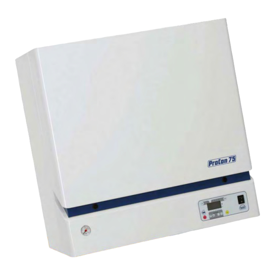
Wall mounted with compact dimensions At 750 mm High, 381 mm Deep, and 510 mm Wide for the Procon 15, 25 & 45 boilers, and 750 mm Wide for the Procon 75 boiler, these provide maximum heat output from minimum dimensions without compromising serviceability. -
Page 5: Product Description (Cont'd)
The excess pressure from the combustion system at maximum output is in the order of 400 Pa. This allows for the Procon 15, 25, 45 & 75 to be fl ued over considerable distances providing a great deal of fl exibility in po- sitioning the boiler. -
Page 6: Technical Data & Dimensions
DHW Primary Return (Optional Extra) 22 mm 22 mm 22 mm DHW Primary Flow (Optional Extra) 22 mm 22 mm 22 mm Fig 3.0a – Underside View 15, 25 & 45 Only Fig 3.0a – Underside View 15, 25 & 45 Only... - Page 7 Procon 3.0 Technical Data & Dimensions (cont’d) Plain View 15, 25 & 45 Only Plain View 75 Only Front View 15, 25 & 45 Only Front View 75 Only Underside View 75 Only Underside View 15, 25 & 45 Only...
-
Page 8: Delivery Consignment / Unpacking The Boiler
5.0 Boiler Location The Procon 15, 25, 45 & 75 boiler is not suitable for installation external to a building. The position chosen for the boiler must be a structurally sound wall capable of supporting the weight of the boiler and any ancillaries. -
Page 9: Wall Mounting
Fig 7.0b – Model 75 Illustrated 8.0 Gas Connection The gas connection is located at the base of the appliance in the centre, see fi g 8.1 for Models 15, 25 & 45; see fi g 8.2 for model 75. -
Page 10: Water Connection
Procon 9.0 Water Connection The Procon 15, 25, 45 & 75 boilers MUST only be installed on a sealed, pressurized heating system. The maxi- mum working pressure of the boiler is 3 bar. A safety valve set at 3.0 bar MUST be installed into the heating fl ow pipe adjacent to the appliance and before any isolation valves. -
Page 11: Flue
EPDM O-rings and male ends of the tubes and fi ttings should be lightly lubricated with silicone grease. ∅ A range of 80 mm PPS fl ue components are available from RVR Boilers Ltd; and is listed on page 15. 11.2 Modular Conventional Flue The Procon 15, 25, 45 & 75 boilers can be connected onto common conventional fl ue, in a modular arrangement;... -
Page 12: Room Sealed Flue
The Procon 15, 25, 45 & 75 boilers are fi tted with a concentric fl ue outlet on the top of the boiler and uses a female 80 mm ∅... - Page 13 (L1). For the 15, 25 & 45 models, add 275 mm to the sum of Length ‘L1 + W’ , to achieve total length ‘TL’ of fl ue piperequired.
-
Page 14: Calculating The Flue Pressure Loss
93° Bend 12.0 45° Bend 1.25 80 mm ∅ PPS Flue Components Concentric to Twin Pipe Adapter 10.0 Exhaust Pipe Terminal Air Pipe Terminal 15.0 1000 mm Flue Extension 500 mm Flue Extension 0.75 2.25 93° Bend 45° Bend 0.75 2.25... -
Page 15: Flue Terminal Positions
13.0 Flue Terminal Positions The fl ue terminal of the Procon 15, 25, 45 & 75 boilers’ will plume water vapour, heavily and care must be taken when selecting the terminal position to ensure that a “nuisance situation” is not created. -
Page 16: Ventilation Requirements
Procon 14.0 Ventilation Requirements The room or space in which the Procon 15, 25, 45 & 75 boiler is installed may need to be ventilated in accord- ance with BS 5440: Part 2:2000, or BS 6644: 2005, as appropriate. The table below details the ventilation required for individual Procon 15, 25, 45 & 75 boiler installations ONLY. -
Page 17: Low Water Pressure Protection
15.3 Care With The Use of Solder Flux The Procon 15, 25, 45 & 75 boiler has a heat exchanger fabricated from 316L Stainless Steel. It is most important that the compatibility of any fl ux is checked with the supplier before use, and that any fl ux manufactures recommendations are strictly followed with regards to use in conjunction with Stainless Steel. -
Page 18: Filling The System
Air Pressure setting. The Procon 15 & 25 boilers only, are supplied with an internal 10-litre expansion vessel. This vessel is suitable for a system with a maximum capacity of 100 litres. This is based upon a Cold Fill Pressure of 1.0bar, and a Final Working Pressure (HOT) of 2.5bar. -
Page 19: Electrical Connections
Air Pressure setting. The Procon 15 & 25 boilers ONLY, are supplied with an internal 10-litre expansion vessel. This vessel is suitable for a system with a maximum capacity of 100 litres. This is based upon a Cold Fill Pressure of 1.0bar, and a Final Working Pressure (HOT) of 2.5bar. -
Page 20: Internal Wiring Diagrams
Procon 16.1 Internal Wiring Diagrams Fig 16.1a – Internal Wiring Diagram for Models 15, 25 & 45 Fig 16.1b – Internal Wiring Diagram for Model 75... -
Page 21: Low Voltage Cables
Procon 16.2 Low Voltage Cables All low voltage cables should be of a suitable screened type for Cable Details 24-volt data transfer. Length (mtrs) Cable (∅ mm 2) The Outside Air Sensor (QAC34), and optional QAA73 unit and Hot Up to 35 0.25... -
Page 22: Agu2.511 Clip-In Module Bms Interface
17.5 RVA47 Cascade Controller (Grey) & Housing The RVA47 Cascade Controller (Grey) is a comprehensiveunit that can be wall or control panel mounted, and can control upto twelve Procon 15, 25, 45 & 75 boilers. The RVA47is supplied with 2 No QAD21 System Sensors (fl ow &... -
Page 23: Rva46 Zone Controller (Black)
18.0 System Configurations. The Procon 15, 25, 45 & 75 boilers can be connected to a number of diff erent types of heating and hot water systems. Depending upon how the boiler is to be utilized will depend upon how the boiler is wired and con- fi gured in the boilers parameters. -
Page 24: System Type 1
The hydraulic resistance of the Index Circuit MUST NOT exceed the amount of the Residual Head pressure available, please refer to the Technical Data detailed in Section 3.0 • The boiler pump on the Procon 75 must be wired to K2 (Terminals X02-03) Legend... - Page 25 Procon 18.1 System Type 1 (cont’d) Notes *1 Only fi t one type of Room Temperature Control. Fig 18.1c – Wiring Diagram for Model 75 Potential Parameter Changes Applicable to System Type 1. Default New Setting for Line ID Description...
-
Page 26: System Type 2
Procon 18.2 System Type 2. Typical single Procon 15, 25 & 45 boiler installation serving heating and domestic hot water (priority) via a 3 Port Valve. Please note; • The Procon15, 25 & 45 models include an internal pump and therefore an external systempump may not be required. - Page 27 Procon 18.2 System Type 2 (cont’d) Notes *1 Only fi t one type of Room Temperature Control. *2 Parameter Change may be required. Fig 18.2c – Wiring Diagram for Model 75 (Not Recommended, please consider System Type 3) Potential Parameter Changes Applicable to System Type 2.
-
Page 28: System Type 3
Procon 18.3 System Type 3 Typical single Procon 15, 25, 45 & 75 boiler installation serving a heating and domestic hot water (priority) with individual charging pumps, using a low velocity mixing header. Please note; • The Procon15, 25 & 45 models include an internal pump and therefore an external boiler pumpis not required. - Page 29 Procon 18.3 System Type 3 (cont’d) Notes *1 Only fi t one type of Room Temperature Control. *2 Parameter Change may be required. Fig 18.3c – Wiring Diagram for Model 75 Essential Parameter Changes Applicable to System Type 4. Default...
-
Page 30: System Type 4
Procon 18.4 System Type 4. Typical single Procon 15, 25, 45 & 75 boiler installation serving two heating zones and domestic hot water (pri- ority) with individual charging pumps, using a low velocity mixing header. AGU2.500 Clip-In Module required. Please note;... - Page 31 Procon 18.4 System Type 4 (cont’d) Notes *1 Only fi t one type of Room Temperature Control. *2 Parameter Change may be required. *3 Heating Zone 1 *4 Heating Zone 2, via AGU2.500 Clip-In Module. Fig 18.4c – Wiring Diagram for Model 75 Essential Parameter Changes Applicable to System Type 4.
-
Page 32: System Type 5
18.5 System Type 5 Typical single Procon 15, 25, 45 & 75 boiler installation utilizing an AGU2.500 Clip-In Module serving two heat- ing zones, one with a mixing valve, and domestic hot water (priority) with individual charging pumps, using a low velocity mixing header. - Page 33 Procon 18.5 System Type 5 (cont’d) Notes *1 Only fi t one type of Room Temperature Control. *2 Parameter Change may be required. *3 Heating Zone 1 *4 Heating Zone 2, via AGU2.500 Clip-In Module. Fig 18.5c – Wiring Diagram for Model 75 Essential Parameter Changes Applicable to System Type 5.
-
Page 34: System Type 6
18.6 System Type 6. Typical single Procon 15, 25, 45 & 75 boiler installation utilizing an RVA63 Controller serving two heating zones each with a mixing valve, and domestic hot water (priority) with individual charging pumps, using a low veloc- ity mixing header. - Page 35 Procon 18.6 System Type 6 (cont’d) Fig 18.6c – Wiring Diagram for Model 75 Essential Boiler Parameter Changes Applicable to System Type 6. Default New Setting for Line ID Description Setting This System H516 Summer/Winter Changer Over Fig 18.6d – Wiring Diagram for RVA63 Essential RVA63 Parameter Changes Applicable to System Type 6.
- Page 36 Procon 18.7 System Type 7. Typical single Procon 15, 25, 45 & 75 boiler installation utilizing an AGU2.500 Clip-In Module and an RVA63 Controller serving four heating zones, three of which having mixing valves, and domestic hot water (priority) with individual charging pumps, using a low velocity mixing header. RVA63 Controller & Housing, 2 No QAD21/26 fl ow sensors, an AGU2.500 Clip-In Module, a QAD36 fl ow sensor, and an OCI420 Communication Clip-In Module...
-
Page 37: System Type 7
Procon 18.7 System Type 7 (cont’d) Notes *1 Only fi t one type of Room Temperature Control. *2 Parameter Change may be required. *3 Heating Zone 1 *4 Heating Zone 2, via AGU2.500 Clip-In Module. Fig 18.7c – Wiring Diagram for Model 75 Essential Boiler Parameter Changes Applicable to System Type 8. -
Page 38: System Type 8
• The Procon15, 25 & 45 models include an internal pump and therefore an external boiler pump is not required. • The wiring of the internal pump on the Procon 45 MUST be relocated from K2 (Terminals 13 & 14) to K1 (Terminals 16 & 17) •... - Page 39 Procon 18.8 System Type 8 (cont’d) Notes *1 Only fi t one type of Room Temperature Control. *2 Parameter Change may be required. Fig 18.8d – Wiring Diagram for RVA47 Essential RVA47 Parameter Changes Applicable to System Type 8. Default...
-
Page 40: System Type 9
Procon 18.9 System Type 9 Typical multiple Procon 15, 25, 45 & 75 boiler installation utilizing an RVA47 Cascade Manager and a RVA63 Controller, two heating zones, one of which having mixing valves, and domestic hot water with individual charg- ing pumps, using a low velocity mixing header. - Page 41 Procon 18.9 System Type 9 (cont’d) Fig 18.9d – Wiring Diagram for RVA47 Essential RVA47 Parameter Changes Applicable to System Type 9. Default New Setting for Line ID Description Setting This System Summer / Winter Cut-Off Fig 18.9e – Wiring Diagram for RVA63 Essential RVA63 Parameter Changes Applicable to System Type 6.
-
Page 42: System Type 10
Procon 18.10 System Type 10 Typical single Procon 15, 25, 45 & 75 boiler installation serving domestic hot water and heating systems using a low velocity mixing header, single primary pump and two number 2 Port Valves with conventional controllers. - Page 43 Procon 18.10 System Type 10 (cont’d) Fig 18.10c – Wiring Diagram for Model 75 Essential Parameter Changes Applicable to System Type 10. Default New Setting for Line ID Description Setting This System Weather Compensation / Constant Temperature H554-b3 {0 = Constant Temp. 1 = Variable Temp}...
-
Page 44: Commissioning
The Procon MUST be commissioned by a competent engineer who will need, in addition to standard hand tools, a U-Tube or Digital manometer and a combustion analyser. Before attempting to set the Procon to work, the following check list must be worked through. See Section 19.1 19.1 Pre-commissioning Checks... -
Page 45: Control Panel
• Engineers’ Level (via password) - Operating Pa- rameter adjustment. 20.1 Boiler LMU64 Controller The Procon 15, 25, 45 & 75 boiler utilizes the Siemen’s LMU64 boiler controller; this controller has undergone a number of software updates. To ensure you are using the correct reference docu- ment, the software number must be retrieved from the controller. -
Page 46: Controller Display
Procon 20.2 Controller Display The Boiler controller has various levels of access, this section relates to understanding the controller fascia, display symbols and buttons. Actual Boiler Temp Mode Selected LMU Version, or Symbol Manual Reset ERROR Code Mode Selection Button. -
Page 47: Level One Parameters Review And Alternation
Time Switch Heating Zone 1 ▲ P 14 00:00 – 24:00 –:– Second OFF Time Switch Heating Zone 1 ▲ P 15 00:00 – 24:00 –:– Third ON Time Switch Heating Zone 1 ▲ P 16 00:00 – 24:00 –:–... -
Page 48: Lmu64 Controller, Fault Indication
Procon 20.4 LMU64 Controller, Fault Indication If the boiler fails to operate correctly the unit will ‘Lockout’ and require manual intervention to reset the controller. On the LCD display will appear in the bottom ‘Left-Hand’ corner, and a LARGE ERROR code will be displayed. -
Page 49: Reviewing Lmu64 Operating Information
Procon 20.4 LMU64 Controller, Fault Indication (cont’d) If the optional QAA73 Room Unit, RVA47 Cascade Controller, or Sequence Description RVA63 Zone Controller has been connected to the boiler, and a fault Number occurs, the or ER will appear on the display of the respective Unit Fan operating at pre-purge rate as well as the boiler. -
Page 50: Lmu64 Operating Error Codes
Procon 20.6 Reviewing LMU64 Operating Error Codes (cont’d) Line ID Description Comments Number H705 2nd Historical Fault – Operating Error Code Actual Operating Code. Refer to Section 20.6. The number of times that this Operating Error Code H706 3rd Historical Fault – Number of Occurrences... -
Page 51: Boiler Operating Sequence Numeric Indication
Procon 20.8 Boiler Operating Sequence Numeric Indication By pressing the ‘INFO’ button three times, the Boiler Sequence Description Operating Sequence can be witnessed, indicated by Large Number numeric notation on the display. Having reviewed the Operating Sequence, press the ‘MODE’ button once to return to the standard screen. -
Page 52: Setting The Boiler To Work
As with all Gas Appliances, we would highly recommended that a competent heating engineer services the Procon 15, 25, 45 & 75 boilers, at least every 12 months. This is assuming a normal daily usage of 8 – 10 hours. -
Page 53: Routine Cleaning & Maintenance
Procon 15, 25 & 45 models, two cables on the Procon 75 model. d) Disconnect the Earth Lead, HT Cap and Lead from the Ignition Electrode. e) Procon 75 ONLY, Undo the long Hexagon Bar at the top of the Heat Exchanger Fig 22.2a and gently rotate the heat exchanger forward, pivots to the left, See Fig 22.2a. -
Page 54: Full Parameters List
Procon 22.2 Routine Cleaning & Maintenance (Cont’d) i) Following the cleaning of the Heat Exchanger, the condensate syphon must be fl ushed to ensure that all mineral deposits/debris that has been washed from the heat exchanger surface is correctly removed. - Page 55 Procon Default Values Display or Function / Description Range QAA73 H505 Boiler setpoint at design outside temperature 20… 90 °C Minimum fl ow setpoint temperature (20 H506 20… 90 °C °C≤TvSmin≤TvSmax) Maximum fl ow setpoint temperature H507 20… 90 °C (TvSmin≤TvSmax≤90 °C)
- Page 56 Procon Default Values Display or Function / Description Range QAA73 Maximum degree of modulation in heating mode H541 0… 100 % (LmodTL ≤ PhzMax ≤ LmodVL) 0… 9999 H542 Minimum boiler output in kW (lower calorifi c value) 0… 9999...
- Page 57 Procon Default Values Display or Function / Description Range QAA73 b0=0 b0=0 b0=0 b0=0 b1=0 b1=0 b1=0 b1=0 b2=0 b2=0 b2=0 b2=0 b3=0 b3=0 b3=0 b3=0 H560 Setting fl ags 0… 255 b4=0 b4=0 b4=0 b4=0 b5=1 b5=1 b5=1 b5=1...
- Page 58 Procon Default Values Display or Function / Description Range QAA73 Triggering threshold for boiler shutdown at high fl ue gas H592 0… 125 °C temperatures Triggering threshold for output reduction at high fl ue gas H593 0… 125 °C temperatures (limitation) Water pressure above which boiler and pump will be shut 0…...
- Page 59 Procon Default Values Display or Function / Description Range QAA73 Output-related start on controller release in instantaneous DHW heating mode (LmodTL ≤ H624 0… 100 % LmodRgStartDLH ≤ LmodVL) Set limit for the number of operating hours (interval) 0… 9998...
- Page 60 Procon Default Values Display or Function / Description Range QAA73 H711 4th Historical Fault – Operating Error Code H712 5th Historical Fault – Number of Occurrences. H713 5th Historical Fault – Operating Phase. H714 5th Historical Fault – Operating Error Code H715 Current Historical Fault –...
-
Page 61: Exploded Views & Short Parts List
Procon 24.0 Exploded Views & Short Parts List The following diagrams show the internal components for the Procon 15, 25, 45 & 75 Boilers, with a short parts list of the internal components. Before ordering any replacement parts, we would recommend that you consult with RVR boilers Spares Department to confi rm that the parts numbers listed are still current. -
Page 62: Procon 15, 25 & 45
Procon 24.1 Procon 15, 25 & 45 (cont’d) Fig 24.1b Item Item Description Part Number Description Part Number № № Water Pressure Switch SGB405 Flow/Return Sensor SGB805 Heat Exchanger {15} SGB415 Heat Exchanger {25} SGB415 Pump {15} SGB416 Heat Exchanger {45}... - Page 63 Procon 24.1 Procon 15, 25 & 45 (cont’d) Fig 24.1c Item Item Description Part Number Description Part Number № № Gas Valve SGB409 Fan {15} SGB723 Gas Injector {15} (Nat Gas) SBA011 Fan {25} SGB723 Gas Injector {25} (Nat Gas)
-
Page 64: Procon 75
Procon 24.2 Procon 75 Fig 24.2a Item Item Description Part Number Description Part Number № № Pressure Gauge SGB817 Display Module SGB800 Condensate Syphon SGB402 Flue Gas Sensor SGB807 ON/OFF Switch SGB400 LMU64 Controller SGB801... - Page 65 Procon 24.2 Procon 75 (cont’d) Fig 24.2b Item Item Description Part Number Description Part Number № № Heat Exchanger SGB809 Gas Injector (Nat Gas) SBA014 Gas Valve SGB806...
- Page 66 Procon 24.2 Procon 75 (cont’d) Fig 24.2c Item Item Description Part Number Description Part Number № № Heat Exchanger SGB809 Flow / Return Sensor SGB805 Ignition Electrode SGB804 Air Bleed Valve SGB407 Fan (75) SGB803...
- Page 67 Procon...
- Page 68 RVR Limited, Kenmare, Co. Kerry, Ireland Telephone: +353 64 41344 • Fax: +353 64 89520 www.RVR.ie This publication is issued subject to alteration or withdrawal without notice. The illustrations and specifi cations are not binding in detail. All off ers and sales are subject to the Company’s current terms and conditions of sale which are available on www.rvr.ie RVR.ie Ireland’s Online Heating Suppliers...
Need help?
Do you have a question about the 15 and is the answer not in the manual?
Questions and answers