Table of Contents
Advertisement
Instructions for Installation/Set-up, Operation, Servicing, & Storage
Portable Outdoor Use-Only, Power Take-Off (PTO) Generator
Can be used to power individual appliances plugged directly into the generator's outlets, or as a back-up
connection to a building's power supply (via a professionally installed UL-approved transfer switch).
READ and UNDERSTAND this manual completely before using the generator! Failure to properly set up, operate, and
maintain this generator could result in serious injury or death from carbon monoxide poisoning, electric shock,
entanglement, fire, or burns. In addition, PTO shaft and generator can become airborne and cause severe injury if
improperly secured. In particular, be aware of the following hazards:
The running tractor engine gives off carbon monoxide, a poisonous gas that can kill you. You CANNOT smell it, see it, or taste it.
• ONLY run tractor and generator OUTDOORS and AWAY from building air intakes. NEVER run inside any enclosed or semi-
enclosed spaces, including homes, basements, garages, sheds, and boxes. These spaces can trap poisonous gases, EVEN if you run a
fan or open windows.
• Install carbon monoxide alarms inside nearby structures/buildings (battery-operated, or plug-in with battery backup).
• High voltage electricity from generator can kill. DO NOT operate in wet locations. Be sure generator is properly grounded. Use only
UL-listed, outdoor-rated grounded GFCI-equipped extension cords of proper size.
• NEVER plug the generator directly into a wall outlet. ANY connection to a building's electrical system MUST ISOLATE THE
GENERATOR FROM UTILITY POWER via a UL-approved transfer switch installed by a licensed electrician. Otherwise, back feed
from the generator into the power grid could kill utility workers.
• DO NOT overload generator (per rated capacity), and OPERATE ONLY in an area with adequate cooling ventilation so generator
does not overheat and possibly cause fire. Keep all objects at least 7' from generator vent openings. Refer to tractor manual for
minimum safe clearance distance between hot tractor exhaust and nearby combustible materials and structures.
•
ALWAYS keep a fire extinguisher rated "ABC" nearby.
• Failure to properly mount and secure the generator may cause the unit to flip violently during use, which could cause severe injury to
the operator or bystanders, or damage to surrounding objects.
• Never operate the generator without proper PTO guarding, including a freely rotating shaft guard as well as tractor and generator
shields at each end. Clothing or hair can become rapidly entangled in unguarded rotating PTO shaft or connections, resulting in
serious injury or death.
• Make sure PTO driveline shaft is securely locked at both ends. An unlocked PTO shaft can whip or become dangerously airborne.
CHOOSE THE RIGHT GENERATOR FOR YOUR NEEDS. See the "Power load Planning & Management" section of this manual
to determine your power load requirements and then compare to the generator's rated capacity.
INSPECT COMPONENTS: Closely inspect to make sure no components are missing or damaged. See the "Unpacking & Delivery
Inspection" section for instructions on whom to contact to report missing or damaged parts.
MOUNTING IS REQUIRED. You will need to mount this PTO generator to either a reinforced concrete slab or a PTO trailer. See the
"About Your Generator" and "Installation/Initial Set-Up" sections for more information on this requirement.
ARRANGE FOR PROFESSIONAL INSTALLATION of a transfer switch if you will be connecting the generator to your
building's electrical system. See the "Installation/Initial Set-Up" section for more information about this requirement.
®
Owner's Manual
12,000 Watt Continuous (13,000 Watt Surge) Capacity
WARNING
CO Poisoning
Electric shock / Electrocution
Power Take-Off (PTO)
STOP!
Any Questions, Comments, Problems, or Parts Orders
Call NorthStar Product Support 1-800-270-0810
M165929G
ITEM NUMBER: 165929
SERIAL NUMBER: _____________
Fire
Advertisement
Table of Contents

Related Manuals for North Star M165929G


Summary of Contents for North Star M165929G
- Page 1 M165929G ITEM NUMBER: 165929 SERIAL NUMBER: _____________ ® Owner’s Manual Instructions for Installation/Set-up, Operation, Servicing, & Storage Portable Outdoor Use-Only, Power Take-Off (PTO) Generator 12,000 Watt Continuous (13,000 Watt Surge) Capacity Can be used to power individual appliances plugged directly into the generator’s outlets, or as a back-up connection to a building’s power supply (via a professionally installed UL-approved transfer switch).
-
Page 2: Hazard Signal Word Definitions
Hazard Signal Word Definitions... -
Page 3: Table Of Contents
Table of Contents Hazard Signal Word Definitions ....................2 About Your Generator .........................4 Specifications ..........................6 Safety Label Locations........................7 Machine Component Identification.....................8 Power Load Planning & Management ..................10 Installation / Initial Set-Up: 1. Unpacking & Delivery Inspection..................12 2. Planning the Power Load......................13 3. -
Page 4: About Your Generator
About Your Generator Thank you for purchasing your NorthStar PTO generator! About Your Generator This PTO-driven, portable generator is designed to provide up to 12,000 Watts of electrical power (12,000 watts continuous, 13,000 watts surge). Connected to your tractor’s power take-off (PTO)*, the generator can supply power: 1. -
Page 5: Warranty Registration
About Your Generator (cont’d) You must follow all instructions and safety precautions presented throughout this manual. A summary of important safety information can be found at the end of the manual. Keep this manual for reference and review. Proper preparation, operation, and maintenance will result in operator safety as well as best performance and long life of the generator. -
Page 6: Specifications
Specifications – Item #165929 SPECIFICATIONS Item Number 165929 Maximum Output 13000 Watts (W) Continuous Output 12000 Watts (W) Voltage 120 / 240 Volt (V) Phase Single phase (4-wire) Frequency 59.0-63.0 Hertz (Hz) Power Factor Minimum PTO HP 24 HP at 540 RPM Minimum Operating Torque 169.6 pound-foot Input Shaft... -
Page 7: Safety Label Locations
Safety Label Locations – Item #165929 DANGER WARNING A Fire Hazard can arise from: Poisonous Gas Hazard Electric Shock/Electrocution Hazard Tractor engines give off carbon High voltage from generator can kill. Overloading the generator monoxide, an odorless gas that Lack of cooling ventilation NEVER connect generator directly can kill you Contact with hot tractor exhaust... -
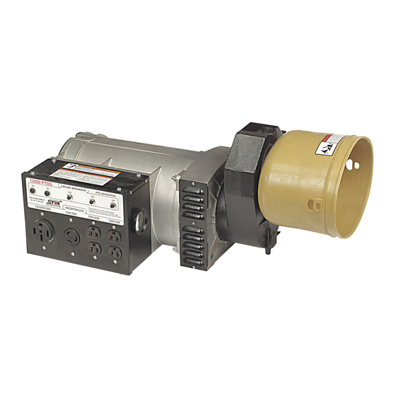
Page 8: Machine Component Identification
Machine Component Identification - Item #165929G Figure 1 (Ref 1-10) Ref. Description Ref. Description 50A Circuit Breakers 120V 30A Locking Receptacle 30A Circuit Breaker 120/240V 50A Receptacle 20A Circuit Breakers Shield 1-3/8”, 6 Spline Input Shaft Gear Box Oil Drain Plug Grounding Screw Fan Vents Mounting Holes... - Page 9 Machine Component Identification – Item #165929G (cont’d) REFERENCE GUIDE Two 50A push-to-reset circuit breakers. Reference 1 – 50A Circuit Breakers Reference 2 – 30A Circuit One 30A push-to-reset circuit breaker. Breakers Two 20A push-to-reset circuit breakers. Reference 3 – 20A Circuit Breakers Reference 4 –...
-
Page 10: Power Load Planning & Management
Power Load Planning & Management WARNING NEVER exceed the rated wattage capacity of your generator. OVERLOADING may cause SERIOUS DAMAGE to the generator and attached electrical devices, and may result in fire. Your generator MUST BE SIZED PROPERLY to provide both the running and starting (surge) wattage of the devices you will be powering. - Page 11 Power Load Planning & Management (cont’d) Running Running Device Watts Device Watts Furnace fan (1/3 HP) 1200 (a) Submersible pump (1-1/2 HP) 2800 (a) Freezer 800 (b) Submersible pump (1 HP) 2000 (a) Hair dryer 1200 Submersible pump (1/2 HP) 1500 (a) Hand drill (1”) 1100...
-
Page 12: Installation / Initial Set-Up
Installation / Initial Set-Up There are a number of important steps required to set up your generator for initial use. These steps are: Steps for Installation / Initial Set-Up 1. Unpacking & delivery inspection. 2. Planning the power load to stay within the generator’s rated capacity. -
Page 13: Planning The Power Load
Installation / Initial Set-Up 2. Planning the Power Load Plan your power load so that you do not exceed the generator’s rated capacity. See the “Power Load Planning & Management” section of this manual to review how to plan and manage power loads for the generator. - Page 14 Installation / Initial Set-Up worker working on what he thinks is a deactivated line could be electrocuted. ♦ If your generator is connected (running or not) when utility power is restored, your generator will be destroyed. It could also explode or cause fire. In addition to isolating your generator from the utility system, the transfer switch connects your generator to a limited set of circuits in your building that have been chosen as critical to operate during a power outage.
- Page 15 Installation / Initial Set-Up (See more technical detail about these receptacles and their associated circuit breakers in the “Machine Component Identification” section of this manual.) ♦ Make sure you plug each electrical device/appliance into the correct generator outlet based on the device’s plug configuration and voltage/amperage rating.
-
Page 16: Selecting A Suitable Site
Installation / Initial Set-Up 4. Select a Suitable Site Before using the generator, you must select a suitable OUTDOOR location for installation and operation of your generator. • If you will be mounting the generator to a concrete slab, you must choose the location of the slab according to all the criteria listed below. - Page 17 Installation / Initial Set-Up equipment, such as another generator. The combined heat that is generated may raise air temperature in the immediate area and there will not be adequate cooling ventilation. • Do not allow debris to accumulate and block airflow. •...
-
Page 18: Mounting The Generator
Installation / Initial Set-Up 5. Mounting the generator This generator must be securely mounted on a reinforced concrete slab or a PTO generator trailer before it is connected to your tractor’s PTO*. This will prevent the generator from flipping due to the rotational torque of the PTO. The slab or trailer you use must be of adequate size and strength to withstand up to 169.6 pound-foot of operating torque without flipping or structural failure. - Page 19 Installation / Initial Set-Up 3. Bolt the generator to the trailer base using three, 7/16” grade 5 bolts. See below. Mounting Holes Note: In order to access two of the mounting holes, you will need to remove the louvered, fan vent panels on both sides. ALWAYS replace panels before starting the generator.
- Page 20 Installation / Initial Set-Up 3. When mounting to a concrete slab, use the optional mount kit, NorthStar item #165935 (available from Northern Tool + Equipment catalog or by calling 1-800-270-0810). The kit comes with two mounting plates. a. Attach the two mounting plates to the generator using the three, grade 5, 7/16”...
-
Page 21: Grounding The Generator
Installation / Initial Set-Up 6. Grounding the generator Always ensure the generator is properly grounded to prevent electrical shock. You must always ground the generator by the following method when using the generator as a portable electrical source: 1) Drive a ¾” or 1” copper pipe or rod into the ground close to the generator. The pipe/rod must penetrate moist earth –... -
Page 22: Operation
Operation Once you have set up your generator for use, it is time to start your generator. The following are the procedures necessary for safe, successful operation of your generator. Operation Procedures 1. General Safety Rules for Operation 2. Preparing for Operation 3. - Page 23 Operation (cont’d) o Excessive vibration o Flame or smoke o Abnormal noise • Adjusting / repairing . Always turn off generator and remove PTO driveline before working on the generator. Always discharge the capacitor before working on the generator head to prevent electrical shock.
-
Page 24: Preparing For Operation
Operation (cont’d) 2. Preparing for Operation Mount Make sure the generator is mounted in accordance with instructions given generator in “Installation / Initial Set-up section, Step 5: Mounting the Generator” of this manual. WARNING: Always ensure generator is properly mounted to prevent it from flipping during use, which could cause equipment damage and injury to nearby persons. -
Page 25: Connecting To The Tractor
Operation (cont’d) WARNING: Burn hazard Never open oil port while generator is running. Hot oil can spray over face and body. IMPORTANT: Under long, continuous-run operating conditions, be prepared to: • Check gear oil level daily. • Change gear oil monthly (see instructions in “Maintenance & Repair” section of this manual). - Page 26 Operation (cont’d) Attach PTO Connect the PTO driveline shaft to the tractor and generator: driveline shaft 1. Align the tractor and generator to minimize the driveline angle in both the horizontal and vertical planes; it should be as near to a direct line in all directions as possible.
-
Page 27: Starting The Generator
Operation (cont’d) 4. Starting the Generator To start the generator: 1. Start the tractor with the PTO control in the “disengaged” position. 2. While seated on the tractor and the engine at idle, engage the PTO. 3. Slowly increase the throttle until the needle in the generator voltmeter is at or above the black line in the green area. - Page 28 Operation (cont’d) into a UL listed voltage surge protector, then plug the surge protector into the generator. 3. After connecting each load, return to the driver’s seat. Readjust the throttle until the needle on the generator’s voltmeter is close to the black line in the green area.
-
Page 29: Stopping
Operation (cont’d) 6. Stopping Stop the generator using the following steps: 1. Disconnect all loads to generator. (Never reduce throttle with electrical loads connected. Damage to generator and loads will occur.) 2. After all loads are disconnected, slowly reduce PTO speed to a minimum and then disengage PTO. -
Page 30: Maintenance & Repair
Maintenance & Repair Inspect and maintain your generator as specified below in order to keep it in safe and optimal working order. Follow all safety rules and recommended maintenance steps. WARNING ALWAYS shut off the engine, remove PTO driveline and discharge the capacitor before cleaning, adjusting, or servicing the generator. - Page 31 Maintenance & Repair (cont’d) 2. Change oil every year: a. Drain oil from gearbox (drain plug is underneath gearbox). b. Replace drain plug. c. Refill with SAE 90W gear oil. Refill so that oil level is even with the red dot. IMPORTANT: Under long, continuous-run operating conditions, be prepared to add and change oil more frequently:...
-
Page 32: Troubleshooting
Troubleshooting TROUBLESHOOTING Problem Possible Causes Possible Remedies Voltage too low. a) Engine speed too slow. a) Increase tractor RPMs. b) Generator is overloaded. b) Reduce the load. (See Power Load Planning & Mgt section of this manual.) Circuit breaker trips. a) Defective load connected to generator. -
Page 33: Summary Of Important Safety Information For Operation
Summary of Important Safety Information for Operation This section provides a summary of the various safety procedures and measures that have been presented throughout the manual. Keep this summary handy and refer to it to refresh your memory about how to safely use your generator. WARNING Carefully read and make sure you understand the following safety information before using the generator. - Page 34 Summary of Important Safety Information for Operation (cont’d) • Isolate connection to building’s electrical circuit. Never plug the generator directly into a wall outlet. ANY connection to a building’s electrical system MUST ISOLATE THE GENERATOR FROM UTILITY POWER via an UL-approved transfer switch installed by a licensed electrician in compliance with all applicable local building and electrical codes.
- Page 35 Summary of Important Safety Information for Operation (cont’d) • Protect sensitive electronics. Some electronic equipment, such as computers and audio/video equipment, can be damaged by small fluctuations in the flow of power. Use a surge suppressor for any voltage-sensitive electronic equipment you will be powering with the generator.
-
Page 36: Generator Exploded View
Generator Exploded View Rev G... - Page 37 Generator Exploded View Rev G Ref # Part # Description 31065 Securing Stud Cap 30997 Grill 307484 Rubber Cup 31011 Brass Jumper 30993 Frame and Stator Assembly 31016 Capacitor 306403 Rear Bearing 307479 Diode 307481 Varistor 30994 Protection Screen 31749 Drive End Bracket 31187 Gear Box...
-
Page 38: Wiring Diagram
Wiring Diagram Rev G... - Page 39 Wiring Diagram Rev G Ref # Part # Description 31085 20A Circuit Breaker 31176 Cover Lid 31086 30A Circuit Breaker 31118 50A Circuit Breaker 306426 20A 120V Duplex Receptacle 306423 30A 120V Locking device Receptacle 31953 50A 120/240V Receptacle 31674 Wire Assembly (W4, W5, W6) 31666 Wire Assembly (B13, B14)
-
Page 40: Gearbox Exploded View
Gearbox Exploded View Rev G Ref # Part # Description 31758 Oil Seal 31757 Large Snap Ring 31761 PTO Shaft External Bearing 31753 PTO Shaft 31760 PTO Shaft Internal Bearing 31762 Oil Plug 31756 Housing 31763 Oil Plug Breather 31754 Gear 31752 Cover... -
Page 41: Limited Warranty
Limited Warranty Dear Valued Customer: The NorthStar Product you just purchased is built with the finest material and craftsmanship. Use this product properly and enjoy the benefits from its high performance. By purchasing a NorthStar product, you show a desire for quality and durability. - Page 42 ® Manufactured by Northern Tool + Equipment Co., 2800 SouthCross Drive West P.O. Box 1499 Burnsville, MN 55337-0499...
Need help?
Do you have a question about the M165929G and is the answer not in the manual?
Questions and answers