Table of Contents
Advertisement
Ins tallation Manual
Revision 5 June 2003
TeleDoorB ell
T M
Don't open your door to the unknown
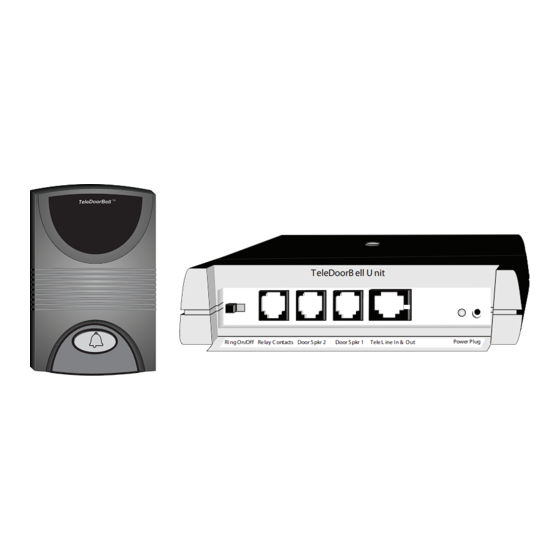
TeleDoorB ell U nit
Power Plug
Ri ng On/Off Relay C ontacts Door S pkr 2
Door S pkr 1
Tele L ine In & Out
6A-7500 Martin Grove Rd. Woodbridge, ON. Canada L4L 8S9
Toll Free: 1.888.790.5900 E-mail: info@logenex.com
For complete information please visit our website at www.logenex.com
Page 1
Advertisement
Table of Contents

Related Manuals for Logenex TeleDoorBell


Summary of Contents for Logenex TeleDoorBell
- Page 1 Ri ng On/Off Relay C ontacts Door S pkr 2 Door S pkr 1 Tele L ine In & Out 6A-7500 Martin Grove Rd. Woodbridge, ON. Canada L4L 8S9 Toll Free: 1.888.790.5900 E-mail: info@logenex.com For complete information please visit our website at www.logenex.com Page 1...
-
Page 2: Table Of Contents
Contents Safety Instructions and guidelines ........... Pg 2 Introduction ..................Pg 3 Features ................... Pg 3 Parts Listing ..................Pg 3 Installation Instructions ..............Pg 4 Installation Diagram ................Pg 6 Additional Installation Diagrams ............Pg 7 Trouble Shooting ................Pg 8 Programming .................. -
Page 3: Introduction
(DOC/CSA/UL approved) Features The TeleDoorBell is a telephone based doorbell system that provides the system user with the capability of communicating with a door speaker from any installed telephone set, including cordless. Unmatched in convenience, this unique new product provides the following features: * System will work as a replacement or in parallel with any standard doorbell. -
Page 4: Installation Instructions
This will provide a bypass capability whereby the telephone line continues to work if the TeleDoorBell unit needs to be removed from the telephone line. Note: If installation is done at a location that has an... - Page 5 Surface mount speaker D-100-F diagram Fig 2 D-100-F Door Speaker Wall / Mounting Installation Surface Initial 1) First drive an initial mounting screw 2” above Mounting the door speaker wiring hole leaving about 1/4” Screw of screw shaft extending from wall. 2) Thread wire through opening at bottom of unit Wiring Hole Note: We recommend that you use...
-
Page 6: Installation Diagram
(CA38A) Alarm Jack Front Door Transformer Disconnect Alarm jack switch and connect Wire is reconnected connection wires together to the TeleDoorBell only if alarm monitored Existing TELCO IN LINE 120V AC doorbell switch Existing from phone company Already connected (to be removed) -
Page 7: Additional Installation Diagrams
Additional TeleDoorBell Connection High-Speed Phone-Line Internet In order for the TeleDoorBell to TeleDoorBell Unit V-200 16V AC work you will have to isolate the Output high-speed modem from the rest TELCO Power Plug Ring On/Off Relay Contacts Door Spkr 2 Door Spkr 1 Tele Line In &... -
Page 8: Trouble Shooting Guide
(output). To test connection, remove the RJ45 wire from the (RJ31X CA38A) data jack which bypasses the TeleDoorBell and/or and connects the phones directly to the main incoming line 2) Check for any breaks in the RJ45 wire, including Data Jack... -
Page 9: Programming
Service Warranty If servicing is needed for the TeleDoorBell, please contact your dealer. The dealer will be able to direct repairs and/or coordinate with the manufacturer. TeleDoorBell products are warranted free from manufacturing defects for a period of one-year following installation. Faulty units will be repaired or replaced at no extra charge to the User except shipping and insurance. - Page 10 6A-7500 Martin Grove Rd. Woodbridge, ON. Canada L4L 8S9 Toll Free: 1.888.790.5900 E-mail: info@logenex.com For complete information please visit our website at www.logenex.com...
Need help?
Do you have a question about the TeleDoorBell and is the answer not in the manual?
Questions and answers