GE Interlogix 60-792-01-95R Installation Instructions Manual
Concord security system
Hide thumbs
Also See for 60-792-01-95R:
- Installation instructions manual (106 pages) ,
- User instructions (68 pages)
Table of Contents
Advertisement
Quick Links
)
Part Numbers:
60-792-01-95R
60-734-01
Concord Security System
(Software Version 2.6)
Installation Instructions
466-1512-01 Rev D
December 2002
*( ,QWHUORJL[
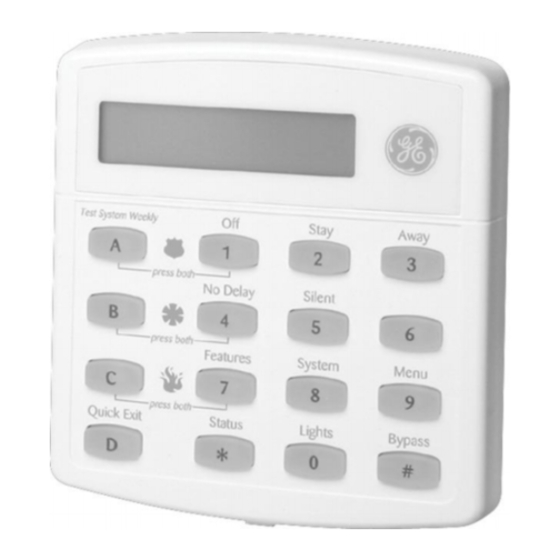
S t a y
A w a y
T e s t S y s t e m
W e e k l y
O f f
A
1
2
3
p r e s s b o t h
N o D e l a y
S i l e n t
P a g e r
B
4
5
6
p r e s s b o t h
F e a t u r e s
S y s t e m
M e n u
C
7
8
9
p r e s s b o t h
S t a t u s
L i g h t s
B y p a s s
D
*
0
#
Q u i c k G u i d e
B y p a s s S e n s o r s
D i s a r m
S y s t e m / C a n c e l A l a r m
1
A r m
s y s t e m t o d e s i r e d l e v e l .
2
P r e s s 1 + C O D E .
P r e s s B Y P A S S + C O D E + S e n s o r N o .
A r m
t o S T A Y
T u r n C H I M E O n / O f f
1
C l o s e a l l p r o t e c t e d d o o r s a n d w i n d o w s .
1
M a k e s u r e s y s t e m
2
P r e s s 2 + C O D E .
2
P r e s s 7 + 1 t o t u r n C H I M E o n o r o f f .
3
P r e s s 4 t o a r m
d e l a y d o o r s i n s t a n t l y ,
P r o g r a m
U s e r S e t t i n g s
i f d e s i r e d .
1
M a k e s u r e s y s t e m
A r m
t o A W A Y
2
P r e s s A o r B t o s c r o l l t h r o u g h m e n u s .
1
C l o s e a l l p r o t e c t e d d o o r s a n d w i n d o w s .
P r e s s # t o s e l e c t o p t i o n o r a c c e p t e n t r y .
2
P r e s s 3 + C O D E .
P r e s s
t o d e s e l e c t o p t i o n o r c a n c e l e n t r y .
3
E x i t p r e m i s e s t h r o u g h d e l a y d o o r .
P r e s s 1 f o r O F F ; p r e s s 2 f o r O N ;
p r e s s 0 - 9 f o r o t h e r e n t r i e s .
Z o n e / S e n s o r N u m b e r
0 1
0 8
0 2
0 9
0 3
1 0
0 4
1 1
0 5
1 2
0 6
1 3
0 7
1 4
S y s t e m
i s O K
A r m e d
R e a d y
S t a y
A w a y
T e s t S y s t e m
W e e k l y
O f f
A
1
2
3
i s d i s a r m e d .
p r e s s b o t h
N o D e l a y
S i l e n t
P a g e r
i s d i s a r m e d .
B
4
5
6
p r e s s b o t h
F e a t u r e s
S y s t e m
M e n u
C
7
8
9
p r e s s b o t h
S t a t u s
L i g h t s
B y p a s s
D
*
0
#
Advertisement
Table of Contents

Related Manuals for GE Interlogix 60-792-01-95R


Summary of Contents for GE Interlogix 60-792-01-95R
-
Page 1: Software Version
466-1512-01 Rev D December 2002 *( ,QWHUORJL[ Part Numbers: 60-792-01-95R 60-734-01 S t a y A w a y T e s t S y s t e m W e e k l y O f f p r e s s b o t h... -
Page 2: Fcc Notices
FCC Notices FCC Part 15 Information to the User Changes or modifications not expressly approved by Interlogix Inc. can void the user’s authority to operate the equipment. FCC Part 15 Class B This equipment has been tested and found to comply with the limits for a Class B digital device, pursuant to part 15 of the FCC Rules. These limits are designed to provide reasonable protection against interference in a residential installation. -
Page 3: Table Of Contents
Contents About This Manual Special Installation Requirements ......................1 UL Listed Installations ..........................1 Central Station Reporting ........................2 UL Canada Listed Installations .......................2 California State Fire Marshall Listed Installations .................3 Planning the Installation Standard Panel ............................3 SuperBus 2000 Touchpads ..........................3 SuperBus 2000 RF Receivers ........................4 Power Line Carrier Card ..........................4 Phone Supervision Card ..........................4 Supervised Wireless Siren ..........................4... - Page 4 Installing Supervised Wireless Sirens (60-736-95) ..................14 Connecting an Interrogator 200 Audio Verification Module (60-677) .............15 Connecting Alphanumeric and Fixed Display Touchpads ...............16 Installing SuperBus 2000 Modules ......................16 SuperBus 2000 RF Receiver (60-764-01-95R-16Z/32Z/MAX) ............17 SuperBus 2000 Phone Interface/Voice Module (60-777-01) ..............17 SuperBus 2000 Energy Saver Module (60-620-01) ................18 SuperBus 2000 8Z Input Module (60-774) ...................19 SuperBus 2000 4-Relay Output Module (60-770) ................19...
- Page 5 Basic System Commands ..........................60 Testing Zones/Sensors ..........................61 If a Wireless Sensor Does Not Test ......................61 Testing Phone Communication .........................62 Testing Central Station/Pager Communication ..................62 Testing Outputs and Sirens ........................63 Testing Light Control ..........................63 Testing the Energy Saver Module (ESM) ....................63 Changing Fixed Display LCD Touchpad Chime and Trouble Beep Tones ..........64 Adjusting Touchpad Display Contrast ......................64 Testing Audio Verification Module (AVM) Communication ..............64...
-
Page 6: About This Manual
Laboratories (UL). This section describes the various component and configuration list- ings. UL Listed Installations This section describes the requirements for UL Listed installations. Basic System • Control Panel (60-734-01 Hybrid or 60-792-01-95R Integrated) • Backup Battery 12V 4 AH (60-681) or 12V 7 AH (60-680) ® • SuperBus... -
Page 7: Central Station Reporting
• Immediate Trouble Beeps set to on • UL 98 Options set to on • Receiver Failure set to on (if wireless devices are used) • Siren Verify set to on • AC Failure set to on • RF TX Timeout set to 4 hours (if system includes a built in or SuperBus 2000 RF Receiver and wireless smoke sensors) UL 1023 &... -
Page 8: California State Fire Marshall Listed Installations
2-wire smoke detectors. • Built-In SuperBus 2000 Receiver (60-792-01-95R only): Allows use of up to 16 or 32 319.5 MHz. crystal and/or SAW Learn Mode wireless sensors and touchpads. Also allows supervision of Supervised Wireless Sirens. -
Page 9: Superbus 2000 Rf Receivers
SuperBus 2000 RF Receivers These receivers expand system wireless zone capacity by 16, 32, or the maximum zones allowed by the panel. The receivers are compatible with all 319.5 MHz. crystal and SAW Learn Mode wireless sensors, touchpads, and Supervised Wireless Sirens. You may connect up to 4 receivers to the panel. -
Page 10: Superbus 2000 Energy Saver Module (Esm)
SuperBus 2000 Energy Saver Module (ESM) Provides a money-saving and convenient way to monitor and control temperatures. The ESM uses low- and high-temperature limits to save energy by overriding the existing HVAC thermo- stat. When the ESM is on, temperature limits determine when the heat or air-conditioning turns on. -
Page 11: Total System Power And Wire Length Guidelines
Phone Jack and 19.25" Optional Module Mounting Area 12" Antenna 9" Area 21" PANEL 12" Allow at least 24” in 45-55" front of the panel to open cabinet door and access panel components. FLOOR Figure 1. Determining Panel Location • Leave space to the left and right of the panel for wiring, phone jack, and mounting optional modules. - Page 12 Table 1: Maximum Device Wire Length and Current Draw (Continued) Max. Wire Length Max. mA Device to Panel Draw 22 ga.—1,800 ft. SuperBus 2000 8Z Input Module 35 mA 18 ga.—4,000 ft. 22 ga.—350 ft. SuperBus 2000 4-Relay Output Module 180 mA 18 ga.—900 ft.
-
Page 13: Mounting The Panel
Table 3: Minimum Device Current Draw Device Min. mA Draw SuperBus 2000 Cellular Backup Module 90 mA SuperBus 2000 Automation Module 30 mA SuperBus 2000 Wireless Gateway Module 55 mA Interrogator 200 10 mA Interrogator AVM 45 mA After determining panel location, run all necessary wires to that location using the guidelines in Table 4. -
Page 14: Identify Panel Components
Mounting Holes Knockout Knockout Mounting Holes Figure 2. Mounting the Panel Identify Panel Before installing devices and making wiring connections, familiarize yourself with the main panel components. Figure 3 shows the main component locations for the hardwire circuit board Components and Figure 4 shows the main component locations for the combination hardwire/wireless circuit board. -
Page 15: Connecting The Panel To Earth Ground
Connecting the Panel to Earth Ground Note For best results, it is recom- For maximum protection from lightning strikes and transients, connect the lower-left circuit mended that you crimp a board screw to earth ground as shown in Figure 5. Use 16-gauge, solid copper wire from an earth spade lug on the wire end at the panel and secure the lug grounded cold water pipe clamp to the panel. -
Page 16: Installing Optional Snapcards
Installing Optional SnapCards The SnapCard Header on the right side of the panel allows for the installation of one SnapCard. Install the desired SnapCard onto the panel SnapCard Header and secure it in place with two screws, included with the card (see Figure 8). Connect all necessary input/output wiring using the Installation Instructions included with the card. -
Page 17: Connecting 4-Wire Smoke Detectors
• System Sensor models 2100D, 2100TD, 2100S, 2100TS, 2400, 2400TH • ESL models 429AT, 521B, 521BXT—(models 521B and 521BXT require the following dip switch settings: 1-on, 2-off) Use only the 2-wire smoke detector models described above. Alarm signals from other detectors may not be processed correctly if the panel has lost AC power and is operat- ing only from the backup battery. -
Page 18: 15-Watt Speaker (13-060)
The output can drive a single 8-ohm speaker or multiple speaker circuit of 8-ohms or higher (as shown in the following speaker wiring diagrams). Compatible speakers are described under “Connecting Piezo Sirens”. To avoid disabling the panel speaker output, do not make speaker connections with the panel powered up. -
Page 19: Connecting Piezo Sirens
Connecting Piezo Sirens Output 1 Onboard output 1 (OUT 1—terminal 9) is an open-collector (switched path-to-ground), program- mable output that can handle a maximum of 200 mA current sink. The default setting (01614) activates the output 15 seconds after a police or fire alarm condition occurs. This allows you to connect a piezo siren without changing the output configuration number in programming. -
Page 20: Connecting An Interrogator 200 Audio Verification Module (60-677)
For supervised operation, the siren has a built-in transmitter that, when learned into panel mem- ory, transmits to the panel receiver if the siren has a low battery or other trouble condition. Before plugging in Supervised Wireless Sirens, the panel must be powered up and partition House Codes and the SWS Supervision Code set (in program mode) to the desired settings. -
Page 21: Connecting Alphanumeric And Fixed Display Touchpads
Black Yellow Splice Run Separate Wire Cables As Shown Cable Shield Panel Terminals + 1 2 V G N D M I C Speaker Figure 19. Connecting an Interrogator 200 AVM to the Panel Connecting Alphanumeric and Fixed Display Touchpads Alphanumeric and Fixed Display touchpads use the same color-coded wire scheme. -
Page 22: Superbus 2000 Rf Receiver (60-764-01-95R-16Z/32Z/Max)
• One SuperBus 2000 RF Receiver can be installed inside the cabinet, but it must be mounted on the right-hand side to accommodate the antennas (see Figure 22). Additional receivers must be installed outside the cabinet. Side Mounting Clips (6) Mounting Clip Receiver... -
Page 23: Superbus 2000 Energy Saver Module (60-620-01)
Phone Interface/Voice Phone Interface/Voice Module Terminal Strip 2 Module Terminal Strip 1 + 1 2 V G N D G N D S P K 1 S P K 2 A U D 1 A U D 2 G N D T I P 1 T I P 2 R I N G... -
Page 24: Superbus 2000 8Z Input Module (60-774)
ENERGY SAVER MODULE THERMOSTAT HEAT 1 2 3 4 5 6 HVAC +12V PANEL TERMINALS Figure 28. Connecting the Energy Saver Module SuperBus 2000 8Z Input Module (60-774) Connect the SuperBus 2000 8Z Input Module to the panel as shown in Figure 29. Connect all necessary input wiring using the Installation Instructions included with module. -
Page 25: Superbus 2000 Automation Module
1 2 3 4 5 6 Panel G N D + 1 2 V B U S 6 0 7 3 4 g 3 0 6 d . d s f Terminals Figure 31. Connecting the Cellular Backup Module to the Panel SuperBus 2000 Automation Module (60-783-02) Connect the SuperBus 2000 Automation Module to the panel as shown in Figure 32. -
Page 26: Setting Device Address On Superbus 2000 Devices
Setting Device Address on SuperBus 2000 Devices When the panel is powered up it automatically assigns device addresses and unit numbers to SuperBus 2000 devices, enabling the panel and module to communicate. Installing an RJ-31X Phone Jack (13-081) Note The panel cannot be used Use the following guidelines when installing an RJ-31X phone jack for system control by phone on a digital or PBX phone and central station monitoring. -
Page 27: Connecting The Ac Power Transformer
Connecting the AC Power Transformer The panel must be powered by a plug-in stepdown transformer that supplies 24 VAC, 30 VA (60- 761) or 24 VAC, 50 VA (60-778). For systems that include a Power Line Carrier card and Supervised Wireless Sirens, or X-10 Lamp Modules, the panel must be powered with the Line Carrier Power Transformer that sup- plies 24 VAC, 30 VA (60-762) or 24 VAC, 50 VA (60-779). -
Page 28: Touchpad Button Programming Functions
¾ Note To enter program mode: If the system is powered up Make sure the system is disarmed in all partitions. after the programming Press 8 + 4321 + 0 + 0. The display shows SYSTEM PROGRAMMING touchpad is connected or if a bus command scan is exe- ¾... -
Page 29: Programming Tier 1 Menu Items
Tier 1 Menu Exit System Demo Kit Partition 1 Clear Programming Programming Off/On Copy Memory Ready Figure 39. Tier 1 Program Menus Arrows pointing right represent pressing B to advance forward through the menus. Pressing A moves through the menus in reverse. The arrow below the menu represents pressing # to advance to tier 2 pro- SYSTEM PROGRAMMING... -
Page 30: Programming Tier 2 Menu Items
• User Code 04 = 1122 (partition 1 code—can also be used to jump to partition 2, for remote or off-site access, and system tests) • User Code 05 = 1122 (partition 2 code—can also be used to jump to partition 1, for remote or off-site access, bypassing sensors, and system tests) •... -
Page 31: Security Menu
Location Menu Name D o w n l o a d e r C o d e ( S e c u r i t y - G l o b a l ) ( 0 0 0 0 ) Shortcut Number Figure 41. - Page 32 ¾ To turn Access Code Lock off or on: Š With the display showing , press 1 (off) or 2 (on). The display ACCESS CODE LOCK ON/OFF flashes the entered setting. Press # and the display shows the new setting. The following sections describe the security settings that appear under PARTITION 1 Account Number (Security—Partition 1-2)
- Page 33 Auto Stay Arming (Security—Partition 1-2) (partition 1: 0014, partition 2: 0024) (Default = on) This setting determines whether or not the system automatically arms to STAY (level 2) if the user arms the system to AWAY (level 3) without exiting the premises. This can help prevent accidental alarms by deactivating interior motion sensors during occupied arming periods.
-
Page 34: Phones Menu
¾ Note To program a Duress Code: Š To use this feature, the With the display showing , enter the desired 4-digit duress code. The dis- DURESS CODE **** Duress Option setting under play flashes the entered setting. Press # and the display shows the new code. reporting—partition 1 (2) menu must be turned on. - Page 35 Exception Rpts (Phones—CS Phone 1-3) (cs phone 1: 0103, cs phone 2: 0113, cs phone 3: 0123) (Default = off) When this setting is on, the panel reports to the central station if the system is not armed or disarmed at the specified schedule times. ¾...
- Page 36 To enter pauses, press C. Note Call-waiting services should To enter *, press and hold 7 for about two seconds. be disabled to prevent inter- To enter #, press and hold 9 for about two seconds. rupting panel communica- ¾ tion to the pager(s).
-
Page 37: Phone Options Menu
Latchkey Reports (Phones—Pager Phone 1-5) (pager 1: 0135, pager 2: 0145, pager 3: 0155, pager 4: 0165, pager 5: 0175) (Default = on) This setting determines whether the panel reports to a pager when the system is armed or disarmed, according to latchkey time scheduling. ¾... - Page 38 Auto Phone Test (Phone Options—Global) (02001) (Default = off) This setting determines if the panel sends a phone test automatically to the central Note For U.L. Commercial Listed station or a pager on a predetermined schedule. (Refer to the “Phone Test Freq.” and “Next installations (UL 1610), this Phone Test”...
- Page 39 Dial Abort Delay (Phone Options—Global) (02006) (Default = 30 sec) This setting determines how much time the user has to abort a panel report. ¾ To change the Dial Abort Delay: Š With the display showing (current setting), enter the desired time DIAL ABORT DELAY nn SECS (15–120s).
- Page 40 Remote Access (Phone Options—Partition 1-2) (partition 1: 0211, partition 2: 0221) (Default = on) When this setting is on, the panel can be accessed from an off-site phone. ¾ To turn Remote Access off or on: Š With the display showing (current setting), press 1 (off) or 2 (on).
-
Page 41: Timers Menu
Phone Access Key (Phone Options—Partition 1-2) (partition 1: 0216, partition 2: 0226) (Default = ) This setting determines which touch-tone phone button is used for system access Note Use the default setting (#) to and control. avoid conflicts between the If the Local Phone Control feature is enabled, the user can pick up the phone and press # (within security system and other phone devices and ser-... - Page 42 Output Trip Time (Timers—Global) (0304) (Default = 4 sec) This setting determines how long outputs are activated when tripped (if they are configured for a momentary response). ¾ To set the Output Trip Time: Š With the display showing (current setting), enter the number of OUTPUT TRIP TIME nn SECS seconds (1–12).
-
Page 43: Light Control Menu
¾ Note To set the Siren Timeout: Š For UL Listed installations, With the display showing (current setting), enter the desired SIREN TIMEOUT nn MINUTES the Siren Timeout must be time value (1–30). The display flashes the entered setting. Press # and the display show the set to 4 minutes or more. -
Page 44: Reporting Menu
ple, if 5 is entered, any keychain touchpads learned into zones 1–5 will be latchkey users and all others (6–76) will not. ¾ To set the number of Latchkey Zones: With the display showing (current setting), enter the desired number of LATCHKEY ZONES nnn latchkey zones (1–76). - Page 45 24-Hour Tamper (Reporting—Global) (06000) (Default = off) When this setting is on, the panel sounds sirens and reports a tamper alarm (even Note For commercial UL Listed when the system is disarmed), when wireless sensor tamper switches are activated. installations (UL 1610) the ¾...
- Page 46 (Default = off) When this setting is on, the panel reports a restoral to the central monitoring sta- Note As with all GE Interlogix pan- tion for wireless or hardwire zones in alarm before the alarm is canceled. els, hardwire smoke detec- ¾...
- Page 47 RF Supv Report (Reporting—Global) (06013) (Default = weekly) This setting determines whether the panel sends daily or weekly reports to the central monitoring station when the panel detects a supervisory condition in a wireless device. ¾ To set RF Supv Report to daily or weekly: Š...
- Page 48 No Activity (Reporting—Partition 1-2) (partition 1: 06103, partition 2: 06203) (Default = off) When this setting is on, the panel sends a no activity report to the central station when the activity timeout expires (see TIMERS—ACTIVITY TIMEOUT ¾ To turn No Activity reports off or on: Š...
-
Page 49: Siren Options Menu
Alarm Verify (Reporting—Partition 1-2) (partition 1: 06108, partition 2: 06208) (Default = off) This setting determines whether the panel reports to the central monitoring station after a single sensor or zone trip (off) or waits for a second trip before reporting (on). This setting affects sensors/zones in groups 10 through 20. -
Page 50: Sensors Menu
¾ Note To set the SWS Supv Code: Š You must set both the SWS With the display showing (current code), enter the desired code (1–255). SWS SUPV CODE nnn Supv Code and the partition The display flashes the entered code. Press # and the display shows the new code. House Code (see the LIGHT menu) before plug-... - Page 51 Learn Sensors (Sensors) Note The panel comes with fac- (080) tory programmed onboard (Default = none) The following describes how to add (learn) hardwire zones and wireless devices hardwire zones. Install 2k- into panel memory. ohm, end of line (EOL) resis- tors on all unused factory ¾...
-
Page 52: Audio Verification Menu
Press # to accept the displayed choice and the display shows: ____ SN 1 ITEM 1 0 -. Repeat steps 5 and 6 as needed to complete the zone or sensor name. Press * after entering the last character or word number. The display shows the complete text name. - Page 53 • (3) Callback Silent—Same as Callback, except premises phones do not ring. ¾ To set Audio Mode: With the display showing , press A or B until the display shows AUDIO VERIFY OFF/ON (current setting). AUDIO MODE nn Enter the desired mode number (1–3). The display flashes the entered setting. Press # and the dis- play shows the new setting.
-
Page 54: Accessory Modules Menu
With the display showing , press A or B until the display shows AUDIO VERIFY OFF/ON (current code). ACCESS CODE nnnn Press D to delete. Accessory Modules Menu ACCESSORY MODULES menu gives you access to the following menus: • —this menu lets you read bus device unit numbers, assign bus devices to a par- BUS DEVICES tition, and configure other features associated with a specific bus device. - Page 55 • Response - how the output responds when trigger event occurs (see Appendix B: Reference Tables). This section describes how to program each of the HOM output point configurations into the security panel. The point configuration number is tttrr, where ttt is the trigger number and rr is the response number.
- Page 56 Cellular System (Acc. Modules—Bus Devices—Unit ID—Cellular Options (Default = B) This setting determines the cellular transmission system (A or B) used for cellular communication. This information is provided by the cellular provider based on installation ZIP code. ¾ To set the Cellular System: Š...
-
Page 57: Onboard Options Menu
# to accept the displayed choice and the display shows: 6. Press OUTPUT N ITEM 1 0 - 7. Repeat steps 4 and 5 as needed to complete the output name. 8. Press * after entering the last character or word number. The display shows the complete text name. -
Page 58: Exiting Programming Mode
Press B and the display shows (current setting). CONFIGURATION tttrr Enter the desired configuration number. The display flashes the entered number. Press # and the display shows the new setting. Press # and repeat steps 2 through 6 until all outputs are programmed. Output Text (Onboard Options—Output Text—Output 1, 2) (1120—output 1, 1121—output 2) (Default = none) Use the following guidelines to “name”... -
Page 59: Time And Date Menu
Time and Date Menu The panel uses a global clock and calendar for time and date. Alphanumeric touchpads display Note Setting the time and date is the panel time and date whenever the system is disarmed. important for accurate track- TIME AND DATE menu lets you set this clock and calendar. - Page 60 With the display showing , press # and the display shows USER CODES REGULAR USER CODES Press # and the display shows nn (first available user number). USER Press A or B to select the desired user number, then press #. The display shows nn - USER nnnn.
-
Page 61: Options Menu
Partition Master (User Codes—Partition Master Code) (partition 1: 0310, partition 2: 0311) (Default = none) The Partition Master Code provides access to all system operations and user programming for a single partition. ¾ Note To change the Partition Master Code: You must be “in”... -
Page 62: Set Up Schedules Menu
¾ Note To adjust status sound Volume: This menu appears only if a Press A or B until the display shows , then press #. OPTIONS Phone Interface/Voice Mod- Next, press A or B until the display shows (current setting). VOLUME n ule is connected to the # and... -
Page 63: Attach Schedules To Events Menu
Attach Schedules to Events Menu ATTACH SCHEDULES TO EVENTS menu lets you link the following system events to time schedules: • Latchkey Opening—sends a report if system is disarmed within the attached time schedule. • Latchkey Closing—sends a report if system is armed within the attached time schedule. •... -
Page 64: Attach Lights To Sensors Menu
Press 1 (off) or 2 (on). The display flashes the entered selection. Press # and the display shows the new setting for the selected schedule. Repeat steps 3, 4, and 5 until all desired outputs are attached to schedules. Arming (Attach Schedules To Events) (0660nn where nn = Schedule number [0 to 15]) (Default = off) This setting lets you arm according to a time schedule. -
Page 65: System Version Menu
System Version Menu SYSTEM VERSION menu lets you view and identify panel hardware and software. This infor- mation is primarily used for troubleshooting purposes. System Version (010 = factory code, 011= system number, 012= system level) (Default = N/A) This menu lets you view and identify panel hardware and software version. ¾... -
Page 66: Testing Zones/Sensors
Table 9: Basic Touchpad Commands (Continued) Command System Response 3 (quick arm on) Arms system to AWAY 2 or 3 + CODE + 4 Arm system—No Delay (no exit or entry delay) 2 or 3 + 4 5 + 2 or 3 + CODE Arms system silently (no arming status beeps) 5 + 2 or 3 7 + 1... -
Page 67: Testing Phone Communication
Testing Phone Communication Perform a phone test to check the phone communication between the panel and the central moni- toring station. ¾ To perform a phone test: Contact the central monitoring station to inform them that you are testing the system. Press 8 + system master CODE + 2. -
Page 68: Testing Outputs And Sirens
Table 11: Pager Sensor/Zone Code and Numbers Code Sensor/Zone or User Number Installer Code used Dealer Code used Quick Arm used Keyswitch Sensor used System Armed Itself (during service or power-up) Testing Outputs and Sirens All outputs (onboard and SnapCard) should be tested to verify configuration programming. Be sure to contact the central monitoring station before activating outputs that trigger from an alarm condition. -
Page 69: Changing Fixed Display Lcd Touchpad Chime And Trouble Beep Tones
Press 7 + 2 to turn on the ESM. The display shows and the ESM relay will Note ENERGY SAVER ON There is a 5-minute delay click once. after the Energy Saver Mod- Press 7 + 2 again to turn the ESM off. The display shows ENERGY SAVER OFF ule returns control to the fur- nace/AC before it will... - Page 70 ¾ To test Cellular Communication: Contact the central monitoring station to inform them that you are testing the system. Install and activate the SuperBus 2000 Cellular Backup Module. Verify or change the following CS PHONE 1 panel option settings. Disconnect the phone line by unplugging the Db-8 cord from the RL-31X Jack. Note If the current settings do not Initiate a phone test (8 + System Master Code + 2).
-
Page 71: Troubleshooting
Troubleshooting This section describes what to do if you experience problems with system operation. If after per- forming the troubleshooting procedures the panel still malfunctions, please call Technical Sup- port at 1-800-777-2624. Feature Problem Action/Solution Panel Power Panel does not power up. Touchpads don’t display or respond. Verify that the panel transformer is plugged into an unswitched outlet. - Page 72 Feature Problem Action/Solution Check your records to see if you have the install code on file. Verify the install code using the Downloader. Use the Dealer Code to enter program mode and view the installer code. Installer cannot remember dealer code. Check your records to see if you have the dealer code on file.
- Page 73 Feature Problem Action/Solution Check that panel is powered up. Check for touchpad power and/or bus miswiring, opens, or shorts. Check touchpad brightness setting (see the user-programming OPTIONS menu in the “Program- ming” section). Touchpad buttons don’t beep when pressed. Check for touchpad power and/or bus miswiring, opens, or shorts. Check that key beeps option is set to on (see the ACCESSORY MODULES—BUS DEVICES menu in the “Programming”...
- Page 74 Feature Problem Action/Solution System doesn’t go into alarm when zone is tripped. System is disarmed. Arm system and then trip the zone. Zone is not learned into panel memory. Enter installer/dealer program mode—LEARN SENSORS, and learn zone into memory. Zone is learned into wrong partition. Delete zone and learn into correct partition or change the partition in the EDIT SENSORS menu.
- Page 75 Feature Problem Action/Solution Wait 2 minutes and try again. The panel may be busy trying to report to the central station. Disconnect the panel DB-8 cord from the RJ-31X jack. If the phone still doesn’t work, the sys- tem is okay and the problem is in the wiring. Check RJ-31X jack wiring and TELCO block wiring.
- Page 76 Feature Problem Action/Solution Verify the Cellular Backup option is on for the CS phone number being tested. Verify that the module is learned on the bus. Check that the Cellular Backup Module has been activated as outlined in the device Installation Instructions.
-
Page 77: Appendix A: System Planning Worksheets
Appendix A: Customer Name _________________________________ System Address _______________________________________ Planning City _________________ County ___________ State ___ Worksheets Zip __________ Phone (____) ___________ Table A1: Wireless Devices Part No. Description Qty. 60-362 Door/Window Sensor 60-670 SAW Door/Window Sensor 60-741-95 Micro Recessed Door/Window Sensor 60-499 Slim Line Door/Window Sensor 60-688... - Page 78 Table A2: Hardwire Devices Part No. Description Qty. Sub Total (Max.) Hardwire Sensors/Detectors 13-068 Magnetic Contact 3/8” press fit 13-070 Magnetic Contact – surface mount System Sensor models 2100D, 2100TD, 2100S, 2100TS, 2400, or 2400TH or ESL 10 mA series 429AT, 521B or 521BXT 13-082 PIR Motion Detector 10 mA...
- Page 79 Table A3: Zone and Sensor Assignments Module Module Bus RF Zone Input Group Partition Zone/Sensor Text ID Number Number...
- Page 80 Table A3: Zone and Sensor Assignments (Continued) Module Module Bus RF Zone Input Group Partition Zone/Sensor Text ID Number Number...
- Page 81 Table A4: System Settings Index and Record Setting (reference) default Shortcut No. Setting Installer Programming—8 + Installer/Dealer CODE + 00 24 Hour Tamper Off 06000 AC Failure Off 06010 Access Code Lock (On) 0003 Access Timeout 90 sec 0904 Account No. 00000 0010, 0020 1_____________2_____________ Activity Timeout 24 hrs...
- Page 82 Table A4: System Settings Index and Record (Continued) Setting (reference) default Shortcut No. Setting Exception Reports (phones) Off 0103, 0113, 0123 1_____________2_____________3___________ 0133, 0143, 0153, 1_____________2_____________3___________ Exception Reports (pagers) Off 0163, 0173 4_____________5_____________ Exit Delay 64 sec 0311, 0321 1_____________2_____________ Exit Extension On 0013, 0023 1_____________2_____________...
- Page 83 Table A4: System Settings Index and Record (Continued) Setting (reference) default Shortcut No. Setting Phone Test On 02000 Phone Test Freq. 7 days 0302 Police Panic On 0512, 0522 1_____________2_____________ Program Report Off 06015 Quick Arm Off 0011, 0021 1_____________2_____________ Quick Exit On 0012.
-
Page 84: Appendix B: Reference Tables
Appendix B: Reference Tables Table B1: Sensor Group Characteristics Name Application Alarm Delay √ √ Fixed Panic 24-hour audible fixed emergency buttons. Police Instant 1, 2, 3 √ Portable Panic 24-hour audible portable emergency buttons. Police Instant 1, 2, 3 √... - Page 85 Table B1: Sensor Group Characteristics (Continued) Name Application Alarm Delay Local Special Notify the user when a door is opened. Sounds emit Special √ Instant 1, 2, 3 Chime from a local annunciator. * Chime √ √ √ Fire 24-hour fire, rate-of-rise heat, and smoke sensors. Fire Instant 1, 2, 3...
- Page 86 Table A2: Item Numbers and Sensor Text Sensor Sensor Sensor Item Item # Item # Sensor Text Item # Item # Item # Sensor Text Sensor Text Text Text Text Aborted Date North Siren Daughter’s Glass Sliding Access Degrees Goodbye Smoke Active Delay...
- Page 87 Table B3: System Event Trigger Numbers Trigger System Event Description Null Trigger (used for direct control) Activated only by schedule or direct command. Fire Alarm When Fire sirens are started. Police Alarm When Police sirens are started. Auxiliary Alarm When Auxiliary sirens are started. Any Audible Alarm When any of the above sirens are started.
- Page 88 Table B4: Sensor Group Event Trigger Numbers Sensor Group Trigger No. Group 00 in alarm Group 01 in alarm Group 02 in alarm Group 03 in alarm Group 04 in alarm Group 05 in alarm Group 06 in alarm Group 07 in alarm Group 08 in alarm Group 09 in alarm Group 10 in alarm...
- Page 89 Table B5: Sensor Number Event Trigger Numbers Sensor Trigger Trigger State State Number Sensor 01 in alarm open Sensor 02 in alarm open Sensor 03 in alarm open Sensor 04 in alarm open Sensor 05 in alarm open Sensor 06 in alarm open Sensor 07...
- Page 90 Table B5: Sensor Number Event Trigger Numbers Sensor Trigger Trigger State State Number Sensor 43 in alarm open Sensor 44 in alarm open Sensor 45 in alarm open Sensor 46 in alarm open Sensor 47 in alarm open Sensor 48 in alarm open Sensor 49...
- Page 91 Table B6: System Feature Event Trigger Numbers Trigger Feature State Phone Test initiated AC Failure for 15 minutes CPU Low Battery detected (excluding first minute after power-up) 227 Auto Phone Test begun Receiver Failure detected Back In Service alarm (AC loss, battery drain, then AC restore) Phone Failure detected Buffer Full...
- Page 92 Table B8: Response Numbers Siren Response Response Trip Delay Tracking Time momentary 3 minutes siren time sustained momentary 3 minutes siren time sustained momentary 3 minutes siren time sustained momentary 3 minutes siren time sustained Notes for Table B8: Response Numbers If an event does not trigger sirens, siren tracking response numbers activate without turning Note The mechanical lifetime of...
-
Page 93: Appendix C: Settings
Appendix C: Settings To Enter Programming Mode: 8 + Installer or Dealer Code + 0 + 0 Tier 1 Menus Tier 2 Menus System Programming Security Phones (Continued) CS Phone 2 CS Phone 2 Global Partition 1 Partition 2 CS Phone 1 Demo Kit On Off Account... - Page 94 Tier 2 Menus (Continued) Phone Options Phones (Continued) Pager Pager Pager Pager Pager Downloader Global Partition 1 Partition 2 Phone 1 Phone 2 Phone 3 Phone 4 Phone 5 Phone Phone Test Local Phone Local Phone Phone Number Phone Number Phone Number Phone Number Phone Number...
- Page 95 Tier 2 Menus (Continued) Timers Light Control Touchpad Options Global Partition 1 Partition 2 Partition 1 Partition 2 Global Partition 1 Partition 2 Entry Delay Sup vs. Time Entry Delay Entry Lights Entry Lights Latchkey Zones Fire Panic Fire Panic 32 secs (32-240) Rndm 1:00-4:00 32 secs (32-240)
- Page 96 Sensor Partition Tier 2 Menus (Continued) Reporting Siren Options Sensors Learn Sensor Delete Edit Global Partition 1 Partition 2 Global Partition 1 Sensors Text Sensors Sensors 0 8 3 0 8 0 0 8 1 0 8 2 Immediate Sensor Text for Sn P1 Gnn Opening Rpts...
- Page 97 Tier 2 Menus (Continued) Audio Verification Accessory Modules Bus Device Partition 1 SnapCards Audio Verify Unit - ID On Off 0 9 0 0 1 0 0 n n ( n n = 0 0 - 1 5 ) Audio Mode 0 9 0 1 Output Output...
-
Page 98: Specifications
Press B to Return Tier 2 Menus To Security Menu Onboard Options Output Output Inputs Programming Text Smoke Verify Output 1 Output 2 Output 1 Output 2 On Off 1 1 0 0 1 1 2 0 1 1 2 1 Partition Partition Output 2... -
Page 99: System Wiring Notes
System Wiring Note 1 Notes Class II power transformer must be plugged into an unswitched AC power receptacle. Do not short the transformer terminals together. The transformer contains an internal fuse that permanently disables the output if the terminals are shorted. Note 2 An alphanumeric touchpad is required for on-site programming. - Page 100 Z O N E 8 Z O N E C O M M O N Z O N E 7 Z O N E 6 Z O N E C O M M O N Z O N E 5 Z O N E 4 Z O N E C O M M O N Z O N E 3...
Need help?
Do you have a question about the 60-792-01-95R and is the answer not in the manual?
Questions and answers