
Related Manuals for Cushman COMMANDER 2100


Summary of Contents for Cushman COMMANDER 2100
- Page 1 606411 A Textron Company OWNER’S MANUAL AND SERVICE GUIDE ELECTRIC POWERED UTILITY VEHICLES ISSUED NOVEMBER 2006 REVISED OCTOBER 2010...
-
Page 2: Safety
S A FE TY For any questions on material contained in this manual, contact an authorized representative for clarification. Read and understand all labels located on the vehicle. Always replace any damaged or missing labels. On steep hills it is possible for vehicles to coast at greater than normal speeds encountered on a flat surface. To pre- vent loss of vehicle control and possible serious injury, speeds should be limited to no more than the maximum speed on level ground. - Page 3 Cushman Division of TEXTRON Inc. is not liable for errors in this manual or for incidental or consequential damages that result from the use of the material in this manual.
-
Page 4: General Information
GENERAL INFORMATION This vehicle has been designed and manufactured in the United States of America (USA) as a ‘World Vehicle’. The Standards and Specifications listed in the following text originate in the USA unless otherwise indicated. The use of non Original Equipment Manufacturer (OEM) approved parts may void the warranty. -
Page 5: Table Of Contents
TABLE OF CONTENTS SAFETY ........................Inside covers GENERAL INFORMATION .......................ii SAFETY INFORMATION ......................vii GENERAL ..........................xi BEFORE INITIAL USE ......................1 Fig. 1 Initial Service Chart ......................1 PORTABLE CHARGER INSTALLATION ......................1 Fig. 2 Proper Charger Installation .....................2 Fig. 3 Charger Receptacle Location ..................2 ON-BOARD CHARGER ............................2 Fig. - Page 6 TABLE OF CONTENTS WHEELS AND TIRES ............................12 Tire Repair ............................12 Wheel Installation ..........................12 Fig. 15 Wheel Installation ....................... 13 LIGHT BULB REPLACEMENT ......................... 13 Fig. 16 Headlight and Turn Signal Bulb Replacement ............13 Fig. 17 Tail and Brake Light Bulb Replacement ..............13 FUSE REPLACEMENT ............................
- Page 7 TABLE OF CONTENTS Fig. 35 Vehicle Dimensions, Incline Specifications and Turning Clearance Diameter ...31 LABELS AND PICTOGRAMS ................Appendix A - 1 LIMITED WARRANTIES ..................Appendix B - 1 DECLARATION OF CONFORMITY (EUROPE ONLY) ........Appendix C - 1 Owner’s Manual and Service Guide Page v...
- Page 8 TABLE OF CONTENTS Notes: Owner’s Manual and Service Guide Page vi...
- Page 9 S A F E T Y I N F O R M ATI O N S A F E T Y I N F O R M ATI O N This manual has been designed to assist in maintaining the vehicle in accordance with procedures developed by the manufacturer.
- Page 10 S A F E T Y I N F O R M ATI O N These vehicles are designed and manufactured for off-road use. They do not conform to Federal Motor Vehicle Safety Standards of the United States of America (USA) and are not equipped for operation on public streets. Some commu- nities may permit these vehicles to be operated on their streets on a limited basis and in accordance with local ordi- nances.
- Page 11 S A F E T Y I N F O R M ATI O N • Follow the manufacturer’s maintenance procedures for the vehicle. Be sure to disable the vehicle before performing any maintenance. Disabling includes removing the key from the key switch and removal of a battery wire. •...
- Page 12 S A F E T Y I N F O R M ATI O N Notes: Owner’s Manual and Service Guide Page x...
-
Page 13: Safety Information
S A F E T Y I N F O R M AT I O N GENERAL The following text is provided as recommended by part II of ANSI/ITSDF B56.8 - 2006. The manufacturer strongly endorses the contents of this specification. 6 GENERAL SAFETY PRACTICES 6.1 Introduction 6.1.1 Like other machines, carriers can cause injury if improperly used or maintained. - Page 14 S A F E T Y I N F O R M AT I O N (1) Arrange for the modification or alteration to be designed, tested, and implemented by an engineer(s) expert in carrier(s) and their safety; (2) Maintain a permanent record of the design, test(s), and implementation of the modification or alteration; (3) Make appropriate changes to the capacity plate(s), decals, tags, and operation and maintenance manuals;...
- Page 15 S A F E T Y I N F O R M AT I O N 6.7 Lighting for Operating Area The user, in accordance with his responsibility to survey the environment and operating conditions, shall determine if the carrier requires lights and, if so, shall equip the carrier with appropriate lights. 6.8 Control of Noxious Gases and Fumes When equipment powered by internal combustion engines is used in enclosed areas, the atmosphere shall be main- tained within limits specified in the American Conference of Governmental Industrial Hygienists publication,:Threshold...
- Page 16 S A F E T Y I N F O R M AT I O N 7.3.1.1 Read and follow operators’ manual 7.3.1.2 Do not operate carrier under the influence of drugs and alcohol. 7.3.1.3 Safeguard the pedestrians at all times. Do not drive carrier in a manner that would endanger other persons. 7.3.1.4 Riding on the carrier by persons other than the operator is authorized only on personnel seat(s) provided by the manufacturer.
-
Page 17: Maintenance Procedures
S A F E T Y I N F O R M AT I O N 7.3.3.2 Handle only stable and safely arranged loads. When handling off-center loads, which cannot be centered, operate with extra caution. 7.3.3.3 Handle only loads within the capacity of each cargo area of the carrier as specified by the manufacturer. 7.3.3.4 Avoid material loads exceeding the physical dimensions of the carrier or as specified by the carrier manu- facturer. - Page 18 S A F E T Y I N F O R M AT I O N k) Brakes, steering mechanisms, speed and directional control mechanisms, warning devices, lights, governors, guards, and safety devices shall be inspected regularly and maintained in accordance with manufacturer’s rec- ommendations.
-
Page 19: Before Initial Use
OPERATION AND SERVICE INFORMATION Read all of Manual to become thoroughly familiar with this vehicle. Pay particular attention to all Notes, Cautions and Warnings Thank you for purchasing this vehicle. Before driving the the ceiling of buildings necessitating proper ventilation. vehicle, we ask you to spend some time reading this Five air exchanges per hour is considered the minimum Owner’s Manual and Service Guide. -
Page 20: On-Board Charger
OPERATION AND SERVICE INFORMATION Read all of Manual to become thoroughly familiar with this vehicle. Pay particular attention to all Notes, Cautions and Warnings Provide Protection From Elements Looping the DC cord through the steering wheel when charg- ing, serves as a good reminder to store the cord out of the way when finished with charging. -
Page 21: Controls And Indicators
OPERATION AND SERVICE INFORMATION Read all of Manual to become thoroughly familiar with this vehicle. Pay particular attention to all Notes, Cautions and Warnings DIRECTION SELECTOR If vehicle is to be charged with a non E-Z-GO charger, refer to To prevent loss of control, do not move Preci- the instructions supplied with the charger. -
Page 22: Accelerator Pedal
OPERATION AND SERVICE INFORMATION Read all of Manual to become thoroughly familiar with this vehicle. Pay particular attention to all Notes, Cautions and Warnings ACCELERATOR PEDAL OPTIONAL FRONT DISC BRAKES The front disc brakes activate as the brake pedal reaches the ‘park’ or latch position. Depressing the brake pedal further will increase the effectiveness of the front Unintentional movement of the accelerator ped- brakes. -
Page 23: Horn
OPERATION AND SERVICE INFORMATION Read all of Manual to become thoroughly familiar with this vehicle. Pay particular attention to all Notes, Cautions and Warnings Horn Ref Hor 1 Fig. 9 Horn Button PLASTIC LOADBED Fig. 8 Run-Tow/Maintenance/Storage Switch The manual lift bed is the standard bed for the vehicle. The bed may be equipped with an optional electric lift switch. -
Page 24: Manual Lift Bed Operation
OPERATION AND SERVICE INFORMATION Read all of Manual to become thoroughly familiar with this vehicle. Pay particular attention to all Notes, Cautions and Warnings Before operating, check to ensure no one is behind the To lower the manual lift bed, grasp the bed handle and lower the bed to the rest position. -
Page 25: Operating The Vehicle
OPERATION AND SERVICE INFORMATION Read all of Manual to become thoroughly familiar with this vehicle. Pay particular attention to all Notes, Cautions and Warnings OPERATING THE VEHICLE foot operated park brake and may cause inadvertent vehicle movement. Turn the key to the ‘OFF’... -
Page 26: Regenerative Braking
OPERATION AND SERVICE INFORMATION Read all of Manual to become thoroughly familiar with this vehicle. Pay particular attention to all Notes, Cautions and Warnings 1. The No Plug performance option: The vehicle’s top is moving between 8 mph (13 kph) and the vehicle’s top speed is sensed and regulated directly by the control- speed. -
Page 27: High Pedal Disable Feature
OPERATION AND SERVICE INFORMATION Read all of Manual to become thoroughly familiar with this vehicle. Pay particular attention to all Notes, Cautions and Warnings Example: If all of the following events occur... a) the system senses that the accelerator pedal is depressed (power applied to motor) When the direction selector is in the reverse position, a warning b) the brake is engaged so as to prevent vehicle... -
Page 28: Labels And Pictograms
OPERATION AND SERVICE INFORMATION Read all of Manual to become thoroughly familiar with this vehicle. Pay particular attention to all Notes, Cautions and Warnings TOWING A TRAILER The vehicle may be equipped with a receiver that can be fitted with a standard 1 7/8" ball. The trailer and its load Some PDS models are equipped with a feature (pedal-up brak- must not exceed 500 lbs (227 kg) and no more than 50 ing) which slows the vehicle’s speed when the accelerator... -
Page 29: Repair
OPERATION AND SERVICE INFORMATION Read all of Manual to become thoroughly familiar with this vehicle. Pay particular attention to all Notes, Cautions and Warnings The painted surfaces of the vehicle provide attractive To raise the entire vehicle, install chocks in front and appearance and durable protection. -
Page 30: Wheels And Tires
OPERATION AND SERVICE INFORMATION Read all of Manual to become thoroughly familiar with this vehicle. Pay particular attention to all Notes, Cautions and Warnings WHEELS AND TIRES faces, tire inflation pressure should be in the higher allowable range, but under no condition should inflation Tire Repair pressure be higher than recommended on tire sidewall. -
Page 31: Fig. 15 Wheel Installation
OPERATION AND SERVICE INFORMATION Read all of Manual to become thoroughly familiar with this vehicle. Pay particular attention to all Notes, Cautions and Warnings To replace the tail and brake light bulb, roll the rubber bezel from around the edge of the taillight and remove lens. -
Page 32: Service And Maintenance
OPERATION AND SERVICE INFORMATION Read all of Manual to become thoroughly familiar with this vehicle. Pay particular attention to all Notes, Cautions and Warnings Always remove windshield before transport- ‘shorting out’ a battery, which could result in ing. an explosion. Maximum speed with sun top installed is 50 The electrolyte in a battery is an acid solu- mph (80 kph). -
Page 33: Serial Number Plate And Location
OPERATION AND SERVICE INFORMATION Read all of Manual to become thoroughly familiar with this vehicle. Pay particular attention to all Notes, Cautions and Warnings To access powertrain for routine maintenance, lift or remove seat. For major repair, refer to appropriate Tech- nician’s Repair and Service Manual. -
Page 34: Periodic Service Schedule
OPERATION AND SERVICE INFORMATION Read all of Manual to become thoroughly familiar with this vehicle. Pay particular attention to all Notes, Cautions and Warnings PERIODIC SERVICE SCHEDULE Check Clean, Adjust, etc. Replace To perform service that is listed in this schedule but not described in this manual, contact a local Service Representa- tive or see the Repair and Service Manual for this vehicle. -
Page 35: Tire Inspection
OPERATION AND SERVICE INFORMATION Read all of Manual to become thoroughly familiar with this vehicle. Pay particular attention to all Notes, Cautions and Warnings Check for bent/binding linkage rod Check for damage or wear to latch arm or catch bracket PARK BRAKE Lubricate as required, use light oil. -
Page 36: Fig. 20 Typical Brake Performance Test
OPERATION AND SERVICE INFORMATION Read all of Manual to become thoroughly familiar with this vehicle. Pay particular attention to all Notes, Cautions and Warnings vehicle should stop aggressively. The wheel brakes may or may not lock. Observe the vehicle stopping location or measure the vehicle stopping distance from the point at which the brakes were latched. -
Page 37: Fig. 21 Add, Check And Drain Axle Lubricant
OPERATION AND SERVICE INFORMATION Read all of Manual to become thoroughly familiar with this vehicle. Pay particular attention to all Notes, Cautions and Warnings Generally, three grades of hardware are used in the vehi- cle. Grade 5 hardware can be identified by the three marks on the hexagonal head and grade 8 hardware is identified by 6 marks on the head. -
Page 38: Battery
OPERATION AND SERVICE INFORMATION Read all of Manual to become thoroughly familiar with this vehicle. Pay particular attention to all Notes, Cautions and Warnings ALL TORQUE FIGURES ARE IN FT. LBS. (Nm) Unless otherwise noted in text, tighten all hardware in accordance with this chart. This chart specifies 'lubricated' torque figures. -
Page 39: Battery Maintenance
OPERATION AND SERVICE INFORMATION Read all of Manual to become thoroughly familiar with this vehicle. Pay particular attention to all Notes, Cautions and Warnings releases stored chemical energy in the form of electrical This level will leave approximately 1/4" - 3/8" (6 - 10 mm) energy. -
Page 40: Fig. 26 Water Purity Table
OPERATION AND SERVICE INFORMATION Read all of Manual to become thoroughly familiar with this vehicle. Pay particular attention to all Notes, Cautions and Warnings Battery Cleaning To prevent battery damage, be sure that all battery caps (if equipped) are tightly installed. To reduce the possibility of damage to vehicle or floor, neutralize acid before rinsing battery. -
Page 41: Battery Replacement
OPERATION AND SERVICE INFORMATION Read all of Manual to become thoroughly familiar with this vehicle. Pay particular attention to all Notes, Cautions and Warnings Battery Replacement of sodium bicarbonate (baking soda) and brush clean if required. Before any electrical service is performed on PDS model To prevent battery explosion that could result in vehicles, the Run-Tow/Maintenance switch must... -
Page 42: Prolonged Storage
OPERATION AND SERVICE INFORMATION Read all of Manual to become thoroughly familiar with this vehicle. Pay particular attention to all Notes, Cautions and Warnings Prolonged Storage BATTERY CHARGING The battery charger is designed to fully charge the bat- tery set. If the batteries are severely deep cycled, some automatic battery chargers contain an electronic module that may not activate and the battery charger will not Battery charger, controller and other electronic devices... -
Page 43: Ac Voltage
OPERATION AND SERVICE INFORMATION Read all of Manual to become thoroughly familiar with this vehicle. Pay particular attention to all Notes, Cautions and Warnings • The charger connector/cord set is protected from point there is nothing that can be done to salvage the damage and is located in an area to prevent injury battery;... -
Page 44: Fig. 32 Hydrometer
OPERATION AND SERVICE INFORMATION Read all of Manual to become thoroughly familiar with this vehicle. Pay particular attention to all Notes, Cautions and Warnings reading of 1.254. Similarly if the temperature was 70° F (21° C), subtract four points (.004) from the Bulb 1.250 to give a corrected reading of 1.246 (Ref Fig. -
Page 45: General Specifications
GENERAL SPECIFICATIONS GENERAL SPECIFICATIONS Owner’s Manual and Service Guide Page 27... -
Page 46: Commander™ 280
GENERAL SPECIFICATIONS ™ COMMANDER STANDARD EQUIPMENT: WEIGHT (without batteries) 675 lbs. (306 kg) TIRES 18 x 8.50 x 8 (4 ply rated)* TIRE PRESSURE 18 - 22 psi (120 - 150 kPa)* LOAD CAPACITY 800 lbs. (362 kg) (including operator, passenger, cargo bed and accessories) GROUND CLEARANCE 4.75 in. -
Page 47: Commander™ 2100
GENERAL SPECIFICATIONS ™ COMMANDER 2100 STANDARD EQUIPMENT: WEIGHT (without batteries) 809 lbs. (374 kg) TIRES (4 ply rated) 18 x 8.50 x 8 (4 ply rated)* TIRE PRESSURE 18 - 22 psi (120 - 150 kPa)* LOAD CAPACITY 1000 lbs. (454 kg) (including operator, passenger, cargo bed and accessories) GROUND CLEARANCE 4.75 in. -
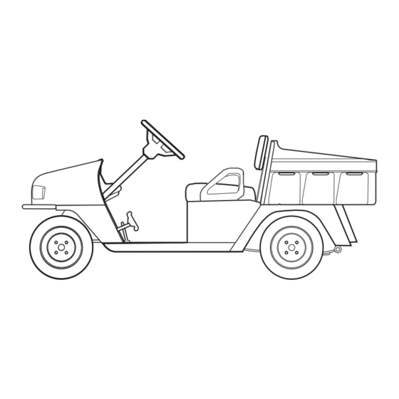
Page 48: Fig. 34 Vehicle Dimensions
GENERAL SPECIFICATIONS 10 in 47 in (25 cm) (119 cm) 66 in (168 cm) (Front) 38 in (97 cm) 103 in (262 cm) (Rear) 35 in (89 cm) 38 in (97 cm) 47 in (119 cm) COMMANDER ™ 280 18 in (46 cm) 47 in ( 119 cm) -
Page 49: Fig. 35 Vehicle Dimensions, Incline Specifications And Turning Clearance Diameter
GENERAL SPECIFICATIONS RECOMMENDED MAX RAMP GRADE RECOMMENDED MAX SIDE TILT 25% or 14 25% or 14 TURNING CLEARANCE DIAMETER COMMANDER ™ 280 19 ft (5.8 m) COMMANDER ™ 2100 22 ft (6.7 m) Fig. 35 Vehicle Dimensions, Incline Specifications and Turning Clearance Diameter Owner’s Manual and Service Guide Page 31... - Page 50 GENERAL SPECIFICATIONS Notes: Owner’s Manual and Service Guide Page 32...
- Page 51 LABELS AND PICTOGRAMS LABELS AND PICTOGRAMS Owner’s Manual and Service Guide Appendix A - 1...
- Page 52 LABELS AND PICTOGRAMS MIN 150 See Following Pages For 614121 Explanation 614121 Of These Pictograms 601781 See Following Pages For Explanation Of These 71129-G02 Pictograms 71129G02 On Battery Under Seat See Following Pages For Explanation Of This Pictogram 35493-G01 74099G01 35493G01 28203G01 See Following...
- Page 53 LABELS AND PICTOGRAMS WARNING WARNING READ MANUAL FOR MAXIMUM LOAD BED CAPACITY. MAXIMUM RAMP/HILL READ MANUAL SECURE LOAD AS FAR FORWARD XXX lbs. AS POSSIBLE. XXX kg MAXIMUM LOAD BED WARNING CAPACITY USE CAUTION IN INCLEMENT WEATHER DO NOT RIDE IN LOAD BED WARNING DO NOT OPERATE...
- Page 54 LABELS AND PICTOGRAMS CLEAN UP GASOLINE SPILLS WITH DO NOT WATER BEFORE DISPOSE OF STARTING ENGINE BATTERIES IN LANDFILL UNLEADED GASOLINE DO NOT DO NOT DRIVE ON SPILL FUEL HIGHWAY ON A HOT ENGINE WINDSHIELDS GROUND DO NOT FUEL PUMP PROVIDE PROTECTION FROM...
- Page 55 LABELS AND PICTOGRAMS HEADLIGHTS KEEP ARMS AND LEGS WITHIN VEHICLE UNLOCKED TO OPERATE VEHICLE IN FORWARD: Q TURN KEY TO ON Q MOVE DIRECTION SELECTOR TO FORWARD Q DEPRESS ACCELERATOR PEDAL LOCKED AND ACCELERATE SMOOTHLY TO OPERATE VEHICLE IN REVERSE: Q TURN KEY TO ON Q MOVE DIRECTION SELECTOR TO REVERSE...
- Page 56 LABELS AND PICTOGRAMS Owner’s Manual and Service Guide Appendix A - 6...
-
Page 57: Limited Warranties
WARRANTY LIMITED WARRANTIES Owner’s Manual and Service Guide Appendix B - 1... -
Page 58: Domestic Warranty
WARRANTY DOMESTIC WARRANTY (U.S. AND CANADA) To obtain a copy of the limited warranty applicable to the vehicle, call or write a local distributor, authorized Branch or the Warranty Department with vehicle serial number and manufacturer date code. Owner’s Manual and Service Guide Appendix B - 2... -
Page 59: Declaration Of Conformity
DECLARATION OF CONFORMITY DECLARATION OF CONFORMITY (EUROPE ONLY) Owner’s Manual and Service Guide Appendix C - 1... - Page 60 DECLARATION OF CONFORMITY Owner’s Manual and Service Guide Appendix C - 2...
- Page 61 DECLARATION OF CONFORMITY Owner’s Manual and Service Guide Appendix C - 3...
- Page 62 DECLARATION OF CONFORMITY Owner’s Manual and Service Guide Appendix C - 4...
- Page 63 Read and understand the following warnings before attempting Read and understand the following text and warnings before to operate the vehicle: attempting to service vehicle: In any product, components will eventually fail to perform properly as the result of normal use, age, wear or abuse. To prevent personal injury or death, observe the It is virtually impossible to anticipate all possible compo- following:...
- Page 64 A Textron Company CUSHMAN Division Of Textron, Inc., 1451 Marvin Griffin Road, Augusta, Georgia USA 30906-3852 TO CONTACT US North America: Technical Assistance & Warranty Phone: 1-800-774-3946, FAX: 1-800-448-8124 Service Parts Phone: 1-888-GET-EZGO (1-888-438-3946), FAX: 1-800-752-6175 International: Phone: 001-706-798-4311, FAX: 001-706-771-4609...
Need help?
Do you have a question about the COMMANDER 2100 and is the answer not in the manual?
Questions and answers