Table of Contents
Advertisement
Installer:
Leave this manual with the appliance.
Consumer:
Retain this manual for future refer-
ence.
WARNING: If the information in these instruc-
tions are not followed exactly, a fire or explosion
may result causing property damage, personal in-
jury or loss of life.
— Do not store or use gasoline or other flammable
vapors and liquids in the vicinity of this or any
other appliance.
— WHAT TO DO IF YOU SMELL GAS
•
Do not try to light any appliance.
•
Do not touch any electrical switch; do not use
any phone in your building.
•
Immediately call your gas supplier from a
neighbor's phone. Follow the gas supplier's
instructions.
•
If you cannot reach your gas supplier, call the
fire department.
— Installation and service must be performed by a
qualified installer, service agency or the gas sup-
plier.
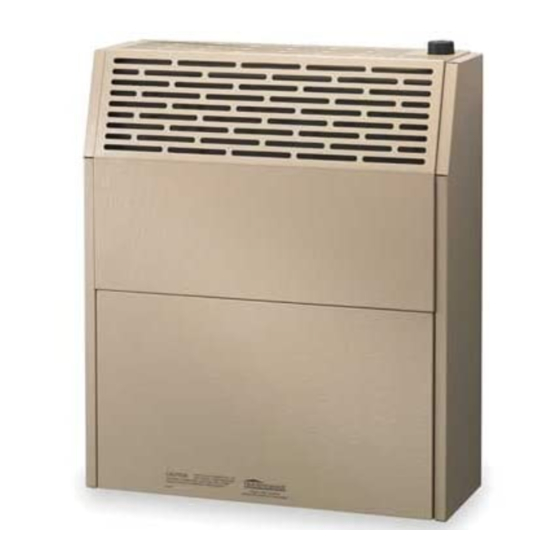
INSTALLATION
INSTRUCTIONS AND
OWNER'S MANUAL
DIRECT VENT
WALL FURNACE
STANDARD MODELS:
HWDV081(N,P)-1
HWDV150(N,P)-1
MODELS WITH BLOWER:
HWDV081B(N,P)-1
HWDV150B(N,P)-1
This appliance may be installed in an aftermarket,
permanently located, manufactured home (USA only),
or mobile home, where not prohibited by state or local
codes.
This appliance is only for use with the type of gas
indicated on the rating plate. This appliance is not
convertible for use with other gases, unless a certified
kit is used.
WARNING: If not installed, operated, and maintained
in accordance with the manufacturer's instructions,
this product could expose you to substances in fuel
or from fuel combustion which can cause death or
serious illness.
DO NOT RETURN THIS PRODUCT TO THE STORE
WHERE YOU PURCHASED IT. IF YOU ARE MISS-
ING PARTS, OR HAVE ANY PROBLEMS, CONTACT
EMPIRE COMFORT SYSTEMS INC. AT (877) 459-1583.
GAS-FIRED
Page 1
Advertisement
Table of Contents


Need help?
Do you have a question about the HWDV081 and is the answer not in the manual?
Questions and answers