Table of Contents

Related Manuals for Camos RV-752


Summary of Contents for Camos RV-752
-
Page 1: Instruction Manual
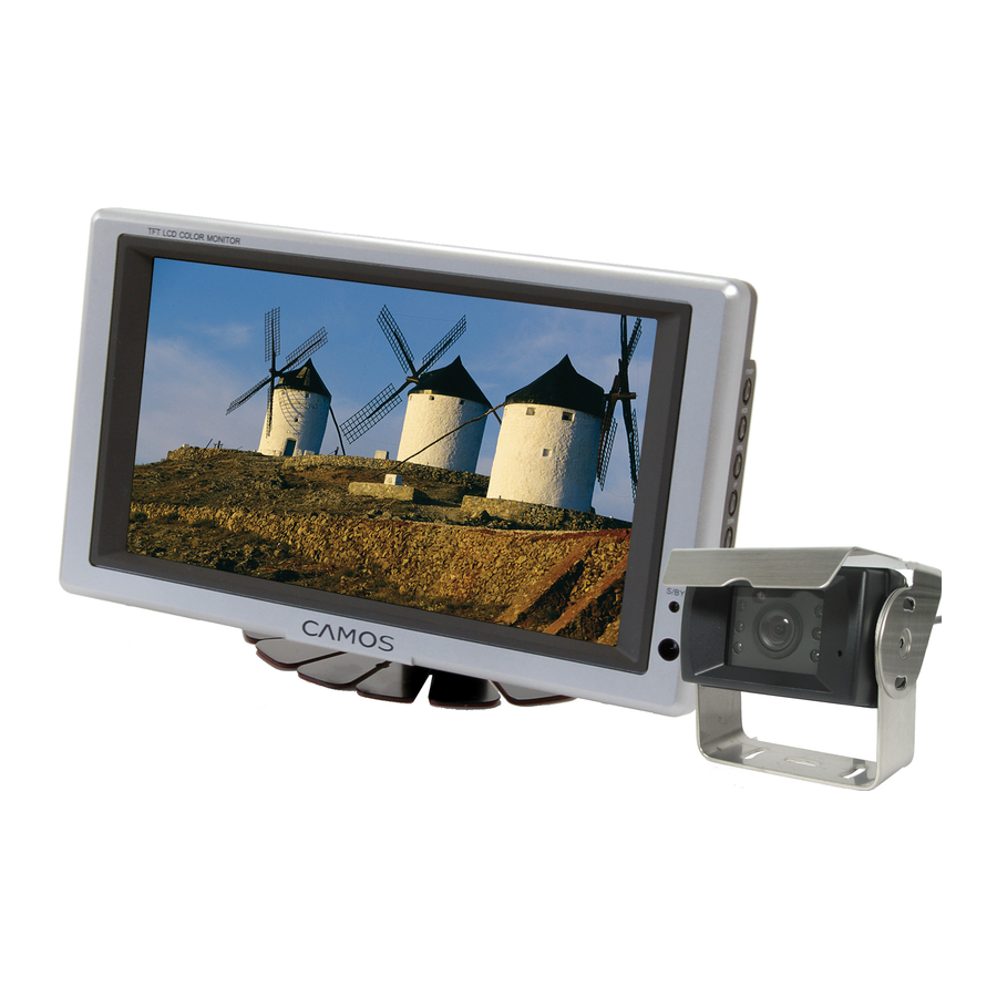
RV-752/-754/-756 7” Rear view system LANGUAGE VEHICLE 5.6” TFT LCD INSTRUCTION MANUAL Thank you for purchasing this product. For proper usages and application, Please read this instruction manual thoroughly ver. 1.5 PRINTED IN KOREA... -
Page 2: Table Of Contents
CONTENTS SAFEGUARD INSTRUCTIONS---------------------------------------- FEATURE ------------------------------------------------------ BOX CONTENTS -------------------------------------------------------- BEDIENELEMENTE ----------------------------------------------------- FUNCTION OF EACH PART ---------------------------------------- FUNCTION ------------------------------------------------------------ CONNECTIONS ---------------------------------------------------- INSTALLATION -------------------------------------------------- SPECIFICATION -------------------------------------------------... -
Page 3: Safeguard Instructions
SAFEGUARD INSTRUCTIONS 7” Rear view system Please read the “Safety Rules” carefully before using this product. Following the safety rules prevents users from damages related with the misuse of the product. It is very important to follow these safety rules. We state “Caution” and “Warning”... - Page 4 WARNING Do not put the product in place where sudden temperature increasing and should use on optimum voltage, temperature and humidity Do not get product wet and operate with wet hands. --- It may cause to electronic shock or malfunction. Do not place where interfere with visual field and watch or operate monitor during driving.
-
Page 5: Feature
FEATURE 7” Rear view system CM-708 • 8bit MICRO controller • TFT LCD with high resolution and low reflection • All functions are displayed on screen (OSD function) • PWM volume control • Mode selection function • Low energy consuming rate •... -
Page 6: Box Contents
BOX CONTENTS 7” Rear view system Cigar Cable Monitor Stand Monitor Cable Optional CM--32 CM-42 CM-46 Accessory Pack FUNCTION OF EACH PART 7” Rear view system Stand-by Display ① S/BY LED Power ON/OFF button ② POWER ③ MODE CAM1 / CAM2 / AV selection function ④... -
Page 7: Function
FUNCTION 7” Rear view system POWER 1) Press [POWER] button to the power. (STAND BY state is OFF) 2) Press [POWER] button again to off the power. MODE • It is a function to change video signal. 1) Press [MODE] button. CAM1 2) CAM1/CAM2/AV1 appears on the screen and it is disappearing 5 sec-... - Page 8 MENU • It is a function to select MAIN MENU (SETUP/PICTURE/CAMERA) 1) Press [MENU] button to select MAIN MENU, changed color in red when it is selected. SETUP PICTURE CAMERA 2) Press [MODE] button to select SUB MENU, UP/DOWN button to change SUB MENU. DIMMER CONTRAST LANGUAGE...
- Page 9 [ 2. PICTURE USER ] 1) MODE button to select CONTRAST, BRIGHTNESS, COLOR, TINT MENU. (Selected menu in red) 2) Push VOLUME UP/DOWN button to change the settings of the diferent menu points. CONTRAST CONTRAST BRIGHTNESS BRIGHTNESS COLOR COLOR TINT TINT CONTRAST CONTRAST...
-
Page 10: Connections
CONNECTIONS 7” Rear view system CAMERA1, 2, AV1... -
Page 11: Installation
INSTALLATION 7” Rear view system (1) Please set the place for Monitor installation. Clean the place where to install stand and install stand firmly after removing protect tape of stand bottom. (2) Fix the stand with enclosed screws. (3) Assemble the monitor to stand and fix it in the right angle. (4) Connect cable as follows. - Page 12 Cameras 1. Determine a position and a direction of installation so that the rear view can be effectively seen on the monitor screen. 2. Fix the camera bracket to the vehicle using the provided adhesive tape and tapping screws. 3. Place a camera and sun visor to fixed bracket and assemble them with enclosed screws.
- Page 13 CM-42 CM-42A Camera connector 1. CAMERA B+ (DC +12V) 2. HEATING B+ (DC +12V) 3. STAND BY 4. VIDEO OUT 5. AUDIO OUT 6. N.C 7. GND CM-46 CM-46 Camera connector 1. CAMERA B+ (DC +12V) 2. HEATING B+ (DC +12V) 3.
-
Page 14: Specification
SPECIFICATION 7” Rear view system CM-708 SPEZIFIKATIONEN PRODUKT NTSC BILDSCHIRMGRÖßE 17,78 cm PIXEL 112,320(H) x 1440(RGB) x 234(V) Pixelabstand 0.107(W) x 0.370(H) mm BILDSCHIRM HELLIGKEIT 400 cd/m ANZEIGEBEREICH 154 (W) x 86.6 (H) mm BLICKWINKEL 60˚(H) / 50˚(U) / 40˚(D) VOLT DC 12V - 24V STROMVERBRAUCH... - Page 15 CM-42 NTSC Pick-up device 1/3” 250,000 pixels COLOR CCD 1/3” 290,000 pixels COLOR CCD 95˚(H) / 70˚(V) / 120˚(D) View of angle 0.1 lux Minimum illumination DC 12V / 200mA Max. Input voltage -15˚C ~ 65˚C (5˚F ~ 149˚F) Operating temperature 78.4(W) x 52.0(H) x 56.5(D) mm / 3.09(W) x 2.04(H) x 2.22(D) (Camera Only) Dimensions 0.4kg / 0.88lbs (including bracket and sunvisor)
- Page 16 Tel. +49 (0) 4154 / 7093202 - 0 Fax. +49 (0) 4154 / 7093202 - 20 E-mail info@camos-multimedia.com Internet www.camos-multimedia.com Address IMC GmbH (Germany) Nikolaus-Otto-Str. 16 D-22946 Trittau...
Need help?
Do you have a question about the RV-752 and is the answer not in the manual?
Questions and answers