junger b42 Operation Manual
B40 series 4ch digital dynamics processor
Hide thumbs
Also See for b42:
- Operation manual (44 pages) ,
- Operation manual (44 pages) ,
- Operation manual (40 pages)
Table of Contents
Advertisement
Quick Links
Advertisement
Table of Contents

Related Manuals for junger b42


Summary of Contents for junger b42
- Page 1 4ch digital dynamics processor release 2.1.0...
- Page 3 If you have any comments or questions about installing, setting- up or using the b42, please do not hesitate to contact us. The information contained in this manual is subject to change without notice. This manual is the copyright of Jünger Audio. All reproduction and copying, other than for legal owner’s personal use, or disclosure of part or whole to a third party, is not allowed without prior written authorization by Jünger Audio.
-
Page 4: Table Of Contents
CONTENTS 2. Function description ........…. 2.1 Basic description ........... 2.2 Block diagram ..........2.3 Audio signal processing ........ 2.3.1 Gain ............2.3.2 Expander ………………………………… 2.3.3 Deesser …………………………………. 2.3.4 Compressor ……………………………... 2.3.5 Limiter ……………........2.3.6 Program ……......... 2.3.7 Transparent mode ........ 2.4 The Jünger Audio Dynamics Principle .. - Page 5 5. Operation ................5.1 adjustment of parameters ………………………………….. 5.2 gain menu …………………………………………………… 5.3 mode menu ………………………………………………… 5.4 expander menu ……………………………………………… 5.5 de-esser menu ……………………………………………… 5.6 compressor menu ………………………………………….. 5.7 limiter menu ………………………………………………… 5.8 utility menu ………………………………………………… 5.9 recall and storage of presets …………………………….. 5.10 editing of presets …………………………………………...
-
Page 7: Function Description
2. FUNCTION DESCRIPTION FUNCTION DESCRIPTION The digital dynamics processor b42 is a professional studio device that processes the dynamic range of digital audio BASIC signals. DESCRIPTION The dynamic range processor principles developed by Jünger Audio enable compressors, limiters and expanders to be... -
Page 8: Block Diagram
2. FUNCTION DESCRIPTION BLOCK DIAGRAM page 2-2 operation manual b40, chapter 2 -Function description-... -
Page 9: Audio Signal Processing
The de-esser of the b42 uses a sophisticated dynamic filtering algorithm for the reduction of S-frequencies. The dynamic filter makes it possible to reduce these frequencies without influencing other spectral parts, and works independent of the signal level. -
Page 10: Compressor
2. FUNCTION DESCRIPTION fig.3: frequency basic function: de-esser auto threshold function S-reduction range 0...-20 filter frequency Input 1..14kHz incl. level male/female [dBFS] 2.3.4 The compression of the programme signal takes place evenly over the entire input level range and not only at the upper end above a COMPRESSOR certain threshold level. -
Page 11: Limiter
(e.g. live atmos, air-conditioning, hum and noise). 2.3.5 The static characteristics of the b42 usually refers to a digital output level of 0 dBFS (dB Full Scale). This is useful for most applications of LIMITER the dynamics processor as the on-following digital recording system is supposed to be balanced down to the final bit. -
Page 12: Transparent Mode
2. FUNCTION DESCRIPTION each kind of programme material. The algorithm has to guarantee best reaction for fast increasing level of transient signals anytime even if classical music with slow dying out characteristic is processed. In all cases the attack time of the limiter for very short transients is zero. Especially the release time of the control circuit has more influence to the increase of loudness as any other parameter. -
Page 13: Selection Of Parameters To Increase Loudness
2. FUNCTION DESCRIPTION The Multi-loop structure also permits a short time delay between the control circuit and the gain changing element. The gain control circuit has time to preview the signal and become active before it reaches the output. This is particularly important for the limiter, which provides a precisely leveled output signal absolutely free of overshoots (clipping). -
Page 14: Influence Of Signal Delay Time
2. FUNCTION DESCRIPTION 2.4.2 The audio signal delay through the dynamics processor is approx. 2ms due to delaying of the audio signal using internal memory. A INFLUENCE OF small delay is deliberately introduced to the audio signal in order to SIGNAL DELAY allow limiter and compressor algorithms which 'preview' the... -
Page 15: Installation
Please examine carefully the packaging and its contents for any signs of physical damage, which may have occured in transit. The digital dynamics processor b42 is a device under the safety POWER SUPPLY category Schutzklasse 1 in keeping with the VDE 0804 standards and may only used with power supply installations built according to regulations. -
Page 16: Synchronization Of Digital Output
3. INSTALLATION The digital dynamics processor b42 has a digital signal output only. To the problem-free combination of following digital devices, SYNCHRONIZATION the digital signal processing can be locked to an external clock reference. The selection of the corresponding input is made in DIGITAL OUTPUT the SYNC MODE menu. -
Page 17: Remote Control
3. INSTALLATION REMOTE CONTROL 3.7.1 The digital dynamics processor b42 can be remote-controlled by GPI REMOTE means of parallel GPI contacts. CONTROL (PARALLEL use : remote-controlled changeover of presets REMOTE) connector: D-SUB 15pin, female Pin assignments Signal name Logic Functions... -
Page 18: Tally Out
3. INSTALLATION 3.7.2 The digital dynamics processor b42 can transmit specific device TALLY OUT statuses via parallel Tally lines. use: Control of the remote-controlled changeover of presets connector: D-SUB 15pin, male Pin assignments Signal name Functions T1 open contact preset1 recalled... -
Page 19: Serial Remote Control
3. INSTALLATION The digital dynamics processor b42 can be remote-controlled by 3.7.3 means of serial remote RS-422. SERIAL REMOTE CONTROL use : remote-controlled changeover of presets (RS-422) protocol: available on request connector: D-SUB 9pin, input - female output - male... -
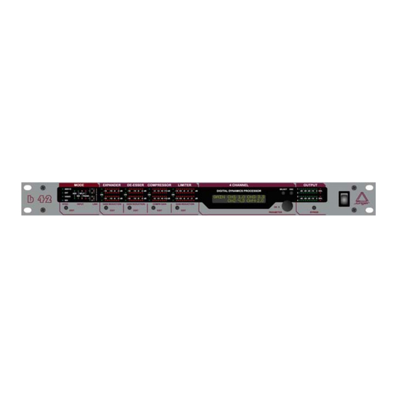
Page 21: Location Of Parts And Controls
DE-ESSER selection/adjustment of de-esser parameter COMPRESSOR selection/adjustment of compressor parameter LIMITER selection/adjustment of limiter parameter 4 CHANNEL selection (push) and adjustment (turn) of processing parameter Operation manual b42, chapter 4 -location of parts and controls - page 4-1... - Page 22 (ENTER) for recall and store of presets exit of adjustment menus and return to level display GAIN selection/adjustment of gain parameter BYPASS switch for general bypass of the unit page 4-2 Operation manual b42, chapter 4 -location of parts and controls -...
-
Page 23: Rear Panel
DIGITAL OUT output for AES/EBU standard format connector: XLR male panel jack 1- ground, 2-3 signal, balanced , 4 Vpp connector: BNC socket 75 Ohm, unbalanced, 0.5V pp Operation manual b42, chapter 4 -location of parts and controls - page 4-3... -
Page 24: Switches And Jumpers For Configuration
After setting of jumper or switches reassemble the unit in opposite order. Interface SDI Split Download DSP card Main board page 4-4 Operation manual b42, chapter 4 -location of parts and controls -... -
Page 25: Selection Of Sdi Split Mode
(Usually used by most of D-VTR's and other equipment is Group 1 with 48 kHz synchronous sampling.) Group selection and other settings are to configure with settings by front panel operation (mode section). Operation manual b42, chapter 4 -location of parts and controls - page 4-5... -
Page 27: Operation
5. OPERATION OPERATION The use of the digital dynamics processor b42 is very easy. DESCRIPTION OF OPERATIONS The setup or the programming of the digital dynamics processor b42 is made by adjustment of various parameters and settings. The description is made related to the functions in the menus. -
Page 28: Adjustment Of Parameters
MODE MENU unit. There are two windows available by pushing MODE EDIT button once or twice. Adjustments are made by pushing and turning CONTROL knob (see 5.1). Return to level display with EXIT. page 5-2 operation manual b42, chapter 5 -Operation-... - Page 29 3. menu (just if SDI interface is present) SDI GROUPS: > IN< selection of SDI group for deembedding input signals 1...4 OUT: selection of SDI group for embedding output signals 1...4 operation manual b42, chapter 5 -Operation- page 5-3...
-
Page 30: Expander Menu
PR CH >CMP< RATIO RNG number of current preset selected channel (change with SELECT) CMP: compressor on/off RATIO: compressor ratio 1.0:1 ...4.0:1 RNG: compression range (maximum compression gain) 0 ... +15 dB page 5-4 operation manual b42, chapter 5 -Operation-... -
Page 31: Limiter Menu
Inside this range the time constants can be varied by the adaptive processing. Setting the range of time constant values may be sometimes useful, to get the best signal processing performance regarding specific programme material. operation manual b42, chapter 5 -Operation- page 5-5... -
Page 32: Utility Menu
If the display is not showing level meter push EXIT button to switch back to level display. SELECT selection of PRESET menu push CONTROL selection of LOAD or SAVE menu turn SELECT change to PRESET selection menu push page 5-6 operation manual b42, chapter 5 -Operation-... -
Page 33: Editing Of Presets
10 presets are storable into the unit. PRESETS In future these presets can be changed off-line, that means without influencing running audio on the machine. This function is currently not available. operation manual b42, chapter 5 -Operation- page 5-7... - Page 34 LIM = ON , THRSH = - 9 , PRO= 8 COMPRESSOR: COPM = ON , RATIO = 1.3 , RNG = 10 DE-ESSER : DEES = OFF EXPANDER: EXP = ON , THRSH =- 50, REL=slow page 5-8 operation manual b42, chapter 5 -Operation-...
-
Page 35: Boot Display And Trouble Shooting
# SDI: sync on SDI input ! check the availability of SDI NO SDI! SDI input selected, no valid SDI signal data stream received! ! select another input Operation manual b42, chapter 6 -Boot display and trouble shooting- page 6-1... -
Page 36: Initialization The Unit
7.1), the device is ready for operation with the factory setup. After an initialization of the device, all user presets and adjustments are erased and/or overwritten by the factory setup! page 6-2 Operation manual b42, chapter 6 -Boot display and trouble shooting-... -
Page 37: Application Notes
AES output. In Split Mode the audio path is splitted. Embedded audio can be processed with external equipment via AES interface. Following illustration shows working modes: operation manual b42, chapter 7-Application notes- page 7-1... - Page 38 7. APPLICATION NOTES page 7-2 operation manual b42, chapter 7-Application notes-...
-
Page 39: Technical Specifications
: 0,5 ... 5 Vpp input format : AES professional, AES consumer VIDEO connector : BNC, 75 Ohm, coaxial level : 0...1 Vpp input format : Blackburst or PAL/NTSC composite video operation manual b42, chapter 8-Technical specifications- page 8-1... - Page 40 : 15 pin SUB-D male GENERAL power consumption : appr. 15 VA dimensions : 19“, 1 RU, 250 mm depth weight : appr. 5 kg optional : programmable remote control brc page 8-2 operation manual b42, chapter 8-Technical specifications-...
-
Page 41: Warranty And Service Information
If the unit has to be serviced, please send it, ideally in the original box, to: JÜNGER AUDIO - Studiotechnik GmbH Justus-von-Liebig-Str. 7 D - 12489 Berlin GERMANY Tel.: (*49) -30-677721-0 Fax.: (*49) -30-677721-46 operation manual b42, chapter 9 -Warranty and service information- page 9-1...
Need help?
Do you have a question about the b42 and is the answer not in the manual?
Questions and answers