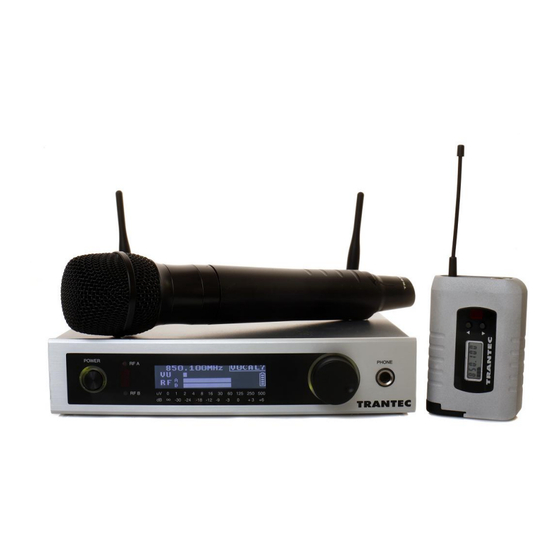
Trantec S5 Series Installation Manual
S5 wireless microphone series
Hide thumbs
Also See for S5 Series:
- Quick installation manual (12 pages) ,
- Quick installation manual (12 pages)

Related Manuals for Trantec S5 Series


Summary of Contents for Trantec S5 Series
- Page 1 Installation Guide...
-
Page 2: Table Of Contents
23, 24. Rack Mount Kit Multi-Channel Configuration with ADU Antenna Head Amplifiers 27, 28. Mini-XLR Wiring Connections 29, 30. Technical Specifications Warranty CE Declaration of Conformity, WEEE Statement Page 1 of 33 – S5 Wireless Microphone Installation Guide Rev 1.2... - Page 3 • Fully integrated PC software monitoring facility via USB port • All metal construction of receiver and transmitters • Rack kit and front mounting antenna adaptors included (S5.5 only) Page 2 of 33 – S5 Wireless Microphone Installation Guide Rev 1.2...
- Page 4 AC adaptor from the AC outlet immediately and contact your nearest dealer. • Smoke or unusual smell • Water or foreign metallic object inside unit • Physically damaged housings Page 3 of 33 – S5 Wireless Microphone Installation Guide Rev 1.2...
- Page 5 Page 4 of 33 – S5 Wireless Microphone Installation Guide Rev 1.2...
-
Page 6: Getting Started
Getting Started The S5 series is a high quality, fully featured wireless microphone system with many features, including an intuitive operating system. To enable you to get started we recommend you initially set up the system as outlined in the next few pages. - Page 7 4. Switch the On/Off switch to the “On” position. The switch surround will now be illuminated green and the receiver will default to its initial setting (BK1.01). The system is now ready for use. Page 6 of 33 – S5 Wireless Microphone Installation Guide Rev 1.2...
-
Page 8: Receiver Frequency Selection
Rotate the “Jog Wheel” till BANK is underlined and press. Press to select BANK1. Rotate the “Jog-wheel” to change the channel. Finally, press to select the new frequency. (See the attached frequency table). Page 7 of 33 – S5 Wireless Microphone Installation Guide Rev 1.2... - Page 9 Press again with ACCEPT underlined to accept the new bank. (See the attached frequency table). Go to step 4 to program the transmitter via the receiver infra-red port. Page 8 of 33 – S5 Wireless Microphone Installation Guide Rev 1.2...
- Page 10 For S5.3 product the single user frequency will be added to the transmitter with receiver Bank1. The S5.3 does not have USER bank. In the case of the S5.5 it will be added to the Custom USER bank. You can download USER banks via the Trantec software. Please refer to the software manual on this CD for more information.
- Page 11 The receiver will return to its main display. For S5.5 - If the receiver is currently in a SINGLE or USER frequency, it will transfer the USER bank.
-
Page 12: Miscellaneous Settings
PHASE REV – reverses the audio output phase. LoCUT – reduces the low frequency response. HiBOOST – increases the high frequency response. Page 11 of 33 – S5 Wireless Microphone Installation Guide Rev 1.2... - Page 13 You can then select any bank from those available, and any frequencies from within those banks. Page 12 of 33 – S5 Wireless Microphone Installation Guide Rev 1.2...
- Page 14 CONTRAST. Push to exit and return to the main screen. The unit will return to the main screen automatically if there is no user intervention for approximately 2 seconds. Any change you have made will be saved. Page 13 of 33 – S5 Wireless Microphone Installation Guide Rev 1.2...
- Page 15 CANCEL. If you are sending Locks to a transmitter you should hold it within 15cm of the receiver and with the infra-red windows of each aligned. Page 14 of 33 – S5 Wireless Microphone Installation Guide Rev 1.2...
-
Page 16: Handheld Transmitter Set-Up
(approx 6 secs) via the “Up” or “Down” buttons. When the correct frequency is selected, turn the transmitter off then on again to activate the newly selected channel. Page 15 of 33 – S5 Wireless Microphone Installation Guide Rev 1.2... - Page 17 7. Mute Switch Incorporated in the handheld end cap is a Power On LED and Audio Mute switch. To Power On mute the audio, flick the switch towards the LED. Page 16 of 33 – S5 Wireless Microphone Installation Guide Rev 1.2...
-
Page 18: Beltpack Transmitter Set-Up
5. Check For Received Signal The receiver should now show a received signal on its RF bar graphs, and after 20 seconds the transmitter battery status. Page 17 of 33 – S5 Wireless Microphone Installation Guide Rev 1.2... - Page 19 (approx 6 secs) via the “Up” or “Down” buttons. When the correct frequency is selected, turn the transmitter off then on again to activate the newly selected channel. Page 18 of 33 – S5 Wireless Microphone Installation Guide Rev 1.2...
-
Page 20: Operating Hints
• Keep the microphone/instrument lead away from the antenna on the beltpack. • Do not mix with other brands of Wireless Microphone as Trantec cannot guarantee multi-channel compatibility. Page 19 of 33 – S5 Wireless Microphone Installation Guide Rev 1.2... -
Page 21: Troubleshooting Guide
• Receiver LCD contrast poor Enter the receiver RX SETTINGS menu, select LCD and press then rotate the “Jog-Wheel” to adjust the contrast. The receiver will automatically exit after a few seconds. Page 20 of 33 – S5 Wireless Microphone Installation Guide Rev 1.2... -
Page 22: S5 System Part Numbers
794-830 MHz S5.5-HDX-C1W UHF Handheld Transmitter (Dynamic Cardioid Capsule) 794-830 MHz S5.5-HCX-C1W UHF Handheld Transmitter (Condenser Capsule) 794-830 MHz S5.5-LTX-C1W UHF Beltpack Transmitter (c/w Lavalier Microphone) 794-830 MHz Cont… Page 21 of 33 – S5 Wireless Microphone Installation Guide Rev 1.2... - Page 23 692-722 MHz S5.5-HDX-A1W UHF Handheld Transmitter (Dynamic Cardioid Capsule) 692-722 MHz S5.5-HCX-A1W UHF Handheld Transmitter (Condenser Capsule) 692-722 MHz S5.5-LTX-A1W UHF Beltpack Transmitter (c/w Lavalier Microphone) 692-722 MHz Page 22 of 33 – S5 Wireless Microphone Installation Guide Rev 1.2...
- Page 24 S5 Series Rack Mount Kit 19” Rack Mounting for 2 x S5 Series Receivers The rack mounting kit is supplied as standard with S5.5 systems, or is available as an accessory for S5.3 systems. 1. Unscrew the front 3 lid retaining screws from opposite sides of each receiver case and fit the angled rack brackets, using the supplied screws.
- Page 25 19” Rack 1 x S5 Series Receiver with Front Mount Antennae The rack mounting kit is supplied as standard with S5.5 systems, or is available as an accessory for S5.3 systems. 1. Unscrew 3 x lid retaining screws (M3x6) from the front left side of the chassis (viewed from the front) and fit the small angled rack bracket, using the supplied screws.
-
Page 26: Multi-Channel Configuration With Adu
Multi-Channel Configuration with ADU The S5 series is designed for simultaneous use of several systems. Ensure each system is assigned a different operating channel. Use only channels from one bank to ensure multi-channel compatibility. Try to ensure that each transmitter is separated by 0.5 M (1.5 ft) during operation. -
Page 27: Antenna Head Amplifiers
Antenna Head Amplifiers Trantec head amplifiers are designed to reduce the effect of long RF antenna cable runs between the receivers or ADUs and remote antennae. The S/ADU and S5 Series Receiver can supply power to the head amplifier. Please note: head amplifiers can introduce some unwanted effects, such as RF blocking and increased intermodulation, especially in multi-channel applications. -
Page 28: Mini-Xlr Wiring Connections
Mini-XLR Wiring Connections Beltpack Audio Mini-XLR Connections 1. Ground 2. Bias 5 V 3. AF Hi-Z 4. AF Load Resistor Solder connections for Mini-XLR flying socket Page 27 of 33 – S5 Wireless Microphone Installation Guide Rev 1.2... - Page 29 Pin 3: AF Hi-Z Pin 4: Internal AF load resistor Link pins 3 and 4 and connect screened cable to pin 1 ground and pins 3 and 4 as illustrated Page 28 of 33 – S5 Wireless Microphone Installation Guide Rev 1.2...
-
Page 30: Technical Specifications
+9 dBm max Antenna Phantom: 9 V @ 60 mA short-circuit protected on each RF port Bank Specification: 10 banks x 24 channels (S5.5) (6 banks Japanese version); 9 banks x 12 channels S5.3 Infra-Red Link: Range 15 cm max... - Page 31 Connector: 4 Pin Mini-XLR Weight: 20.5 g (excl accessories) Due to our continual policy of research and development we reserve the right to alter specifications without prior notice. Page 30 of 33 – S5 Wireless Microphone Installation Guide Rev 1.2...
-
Page 32: Warranty
Warranty All Trantec products are guaranteed for a period of 12 months from the date of purchase against defects in materials and workmanship. In the event of a claim under guarantee the product should be returned in its original packing to an Authorised Service Centre or BBM Electronics, together with proof of purchase, i.e. -
Page 33: Ce Declaration Of Conformity
Please dispose of this product by taking it to your local recycling or collection point. BBM Electronics Group Ltd www.trantec.co.uk A subsidiary of TOA Corporation Page 32 of 33 – S5 Wireless Microphone Installation Guide Rev 1.2...
Need help?
Do you have a question about the S5 Series and is the answer not in the manual?
Questions and answers