Table of Contents
Advertisement
Quick Links
Installation and Operation Instructions
Installation
and Operation
Instructions for
Natco
Fire-Coil
Model 175-400
Volume Water Heaters
FOR YOUR SAFETY: This product must be installed and serviced by a professional service technician,
qualified in hot water heater installation and maintenance. Improper installation and/or operation could
create carbon monoxide gas in flue gases which could cause serious injury, property damage, or death.
Improper installation and/or operation will void the warranty.
If the information in this manual is not followed exactly, a fire or explosion may result
causing property damage, personal injury or loss of life.
Do not store or use gasoline or other flammable vapors and liquids in the vicinity of this or
any other appliance.
• Do not try to light any appliance.
• Do not touch any electrical switch; do not use any phone in your building.
• Immediately call your gas supplier from a nearby phone. Follow the gas supplier's
instructions.
• If you cannot reach your gas supplier, call the fire department.
Installation and service must be performed by a qualified installer, service agency, or gas
supplier.
WARNING
WHAT TO DO IF YOU SMELL GAS
N
N
ATCO
ATCO
Document 2100
Advertisement
Table of Contents

Related Manuals for Natco Fire-Coil 175-400


Summary of Contents for Natco Fire-Coil 175-400
- Page 1 Operation Instructions for Natco Fire-Coil Model 175-400 Volume Water Heaters FOR YOUR SAFETY: This product must be installed and serviced by a professional service technician, qualified in hot water heater installation and maintenance. Improper installation and/or operation could create carbon monoxide gas in flue gases which could cause serious injury, property damage, or death.
-
Page 2: Table Of Contents
ATCO ATCO TABLE OF CONTENTS SECTION 1. SECTION 4. General Information Maintenance Introduction........... 1 General Instructions ........18 Warranty ............1 Replacement of Gas Controls ....19 Technical Assistance ........1 Heat Exchanger .......... 20 4C-1. Inspecting the Heat Exchanger ....20 SECTION 2. -
Page 3: General Information
Natco Fire-Coil Volume Water Heaters Page 1 Make all warranty claims to an authorized Natco SECTION 1. representative or directly to the factory. Claims must General Information include the heater serial number and model (this information can be found on the rating plate), installation date, and name of the installer. -
Page 4: Installation Instructions
(CO) detectors and manufacturer's maintenance schedule of the heater. Install the Fire-Coil heaters in accordance with the procedures in this manual (or the Natco warranty may be voided), local codes and ordinances. In the absence of such codes, install the heaters in accordance with the latest edition of the National Fuel Gas Code, ANSI Z223.1. -
Page 5: Site Location
Natco Fire-Coil Volume Water Heaters Page 3 Remove the vent cap or drafthood from its package. Disengage the flue transition ring from the stack extension and place it on top of the collector assembly as shown in Figure 4. Slide the adapter plate over the bottom of the stack extension as shown in Figure 5. -
Page 6: 3. Flooring - Typical Installation
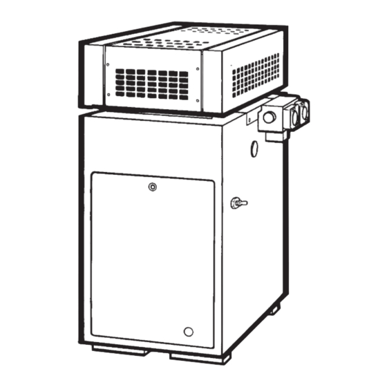
Page 4 Concrete slab must extend out a minimum of 12 in. (305mm) on all sides. WINDOW NATCO OR GRILL UNIT (Side View) Base For Combustible Floors INDOOR ROOM Roof - Wood and Steel Construction Figure 11. Standard base for combustible floor. -
Page 7: 1. Outdoor Air Supply
(see Figure 14 and building, creating a possible health hazard. Table 2 ). Natco does not recommend indoor installations that do not provide combustion air from outside the building. -
Page 8: 2. Replacement Of Existing Heater
PW pump-mounted models. b. Loosen the screw on the capillary tube Natco ships the VW heater with the water retaining clip, then gently pry the clip apart connections on the right side. The VW heater can be until it comes free from the temperature installed with the water connections on either side. - Page 9 Natco Fire-Coil Volume Water Heaters Page 7 HEAT EXCHANGER REAR TILE COVER ASSEMBLY GAP CLOSURE FLOW SWITCH CONDUIT DRAIN PLUG DRAIN VALVE REAR TILE COVER GAP CLOSURE GROMMET DRAIN VALVE HEX HEAD SCREWS METAL CHANNEL (FOR CAPILLARY TUBE) MANUAL RESET...
-
Page 10: 2. Water Chemistry
21. Reinstall the front and rear tile covers. 2F-2. Water Chemistry 22. Push the capillary tube(s) out through the lower Natco equipment is designed to be used in a hole in the left side of the jacket. variety of water conditions. With the proper pump, the water velocity in the heat exchanger tubes is kept high 23. -
Page 11: 3. Freeze Protection
• Natco does not warrant heat exchangers damaged system. The pressure relief valve may discharge hot by scaling, corrosion, or erosion. water under these conditions, causing a loss/waste of energy and a buildup of lime on the relief valve seat. - Page 12 Page 10 Heat Flow Pressure* Water Temp Exch. Water Rate Drop Rise Model Passes Category ° ° Soft Normal 11.2 Hard 19.1 Soft Normal Hard 15.9 Soft Normal 11.2 Hard 19.1 Soft Normal Hard 15.9 Soft 12.5 Normal 12.5 Hard 21.7 Soft 10.4...
- Page 13 Natco Fire-Coil Volume Water Heaters Page 11 Optional Cold Water Supply Hot Water When Adequate Tank Opening to Building Not Available Hot Water Return from Heater Building Throttling Valve Drain Check Valve Bldg. Service Loop Valve Circ. Pump Pump To Drain...
-
Page 14: 9. Pump Installation
Page 12 Fill the bearing assembly to the lower level of the overflow vent. Pressure Add 5 or 6 drops of oil to the front and rear of Relief Valve Flow the motor. Use 20W non-detergent oil. Switch 2F-10. Storage Tank Installation Be sure the floor is structurally capable of supporting the tank when it is filled with water, and is waterproof. -
Page 15: Gas Supply And Piping
Check the rating plate to make sure the heater is threaded cap which can be removed for cleaning. fitted for the type of gas being used. Natco Install a manual gas shutoff valve for service and heaters are normally equipped to operate below a safety. -
Page 16: 2. Special Precautions For Propane Gas
Check heater wiring and pump for correct voltage, frequency, and phase. Check to make sure heater is wired for 120 volts alternating current (VAC). If 240 VAC, contact local factory representative or Natco. Out — Wire the heater and pump exactly as shown in Mixed Water For Potable Use the wiring diagram supplied with the heater. -
Page 17: Operating Instructions
Natco Fire-Coil Volume Water Heaters Page 15 Turn manual gas valve off. SECTION 3. Wait 5 minutes to clear out any gas, then smell Operating Instructions for gas, including near the floor. Be sure to smell next to the floor because some types of gas are 3A. - Page 18 Page 16 IGNITION SYSTEM NO. 1 - STANDING PILOT ON/OFF OR MECHANICAL MODULATION Volume Water Heaters (325-400) Version B Natural or Propane Gas PUMP INCLUDED ON PW MODELS, FIELD SUPPLIED ON VW MODELS Figure 25. Typical example of wiring schematic, System 1.
- Page 19 Natco Fire-Coil Volume Water Heaters Page 17 IGNITION SYSTEM NO. 12 - ELECTRONIC IGNITION ON/OFF OR MECHANICAL MODULATION Volume Water Heaters (325-400) Version B Natural or Propane Gas PUMP INCLUDED ON PW MODELS, FIELD SUPPLIED ON VW MODELS Figure 26. Typical example of wiring schematic, System 12.
-
Page 20: Adjustment For Minimum Input Rate (Models With Modulating Gas Valve)
Page 18 3E. Hi-Limit Switch Checkout Manual Reset Temp. Control After running the heater for a long enough Temperature Controller period, bring the water temperature within the range of the hi-limit switch and slowly back off the high limit setting until the heater shuts off. The main burners should reignite when the hi-limit switch is reset and turned back up to its original setting. -
Page 21: Replacement Of Gas Controls
Natco Fire-Coil Volume Water Heaters Page 19 4B. Replacement of Gas Controls Electronic Pilot Standing Pilot The gas and electric controls installed on the heaters are designed for both dependable operation and long life. Safe operation of the heater depends on their proper functioning. -
Page 22: Heat Exchanger
Page 20 Remove the two screws that fastens the anti- 15. Connect the pilot gas tube to the pilot assembly rotation bracket on the left side of the gas valve and the gas valve. (see Figure 29). 16. Install the anti-rotation bracket to the inner panel Remove the pilot gas tube and copper and fasten with two screws (see Figure 29). -
Page 23: Cleaning The Heat Exchanger
A from the heat exchanger. Do not use water or manometer kit is available from Natco and instructions compressed air for cleaning. for its use are included in the kit. A dry gas pressure NOTE: Use only the correct carbide tipped gauge may also be used for either test. -
Page 24: Checking The Manifold
Page 22 The manometer reading should be 4 inches (102mm) W.C. for natural gas and 9 inches Suggested Manometer (229mm) W.C. for propane gas. Position Turn the toggle switch to OFF. 10. Shut the system down following the instructions found on the inside of the heater. 11. -
Page 25: Testing The Transformer
Natco Fire-Coil Volume Water Heaters Page 23 Make sure the gas valve is on and there is gas pressure in the line. Check all electrical connections and wiring. Finding a loose connection or a charred wire can save a lot of time and money. -
Page 26: Testing The Fusible Link
Page 24 Check for leaks of the flue collector, vent pipe, gaskets, and all connections. Check the flue pipe for blockage. 5B-7. Testing the Fuse To test the fuse: Clip a lead of the voltmeter to the grounding terminal. Touch the other voltmeter lead to the 24VAC terminal on the ignition control. -
Page 27: (For Standing Pilot)
Natco Fire-Coil Volume Water Heaters Page 25 Touch the other voltmeter lead to the red 24V terminal on the ignition control. If the voltmeter reads voltage, the temperature control and the manual reset hi-limit switch are not keeping the heater from firing. -
Page 28: 11. Testing The Safety Shutoff (For Standing Pilot)
Page 26 5B-11. Testing the Safety Shutoff If the voltmeter reads 20 to 28VAC, but there is no pilot ignition, check for (for standing pilot) After lighting the heater, test the ignition system a: air in gas lines. safety shutoff. b: restrictions in gas line, valve or pilot tubing. -
Page 29: 16. Testing For Burner Ignition (For Standing Pilot)
Clip one lead of a volt meter between the yellow provided by Natco. Determine whether or not an wire on the transformer and the brown wire external control is open by checking for voltage at terminal on the gas valve. -
Page 30: Parts List
24. Switch, Drafthood ........E0121000 6A. General Information VENT SYSTEM 26. Vent Cap ..........R0318602-05 To order or purchase parts for the Natco Fire- 27. Drafthood ..........R0318702-05 Coil Volume Water Heaters, contact your nearest 28. Drafthood/Vent Cap Natco wholesaler. If they cannot supply you with what Adapter Plate .......... - Page 31 Natco Fire-Coil Volume Water Heaters Page 29 Item Description Part Number Item Description Part Number 60. Tee JACKET COMPONENTS Bronze ............ P0075600 64. Jacket Assembly ........10568302-05 Cast Iron ..........P0071700 65. Door ............10448902-05 61. Bushing, Brass ........P0018500 66.
- Page 32 National Combustion Company, Inc. 104-07 180 Street, Jamaica, NY 11433 • (718) 291-8400 FAX (718) 291-6870 Litho in U.S.A. © 0610...
Need help?
Do you have a question about the Fire-Coil 175-400 and is the answer not in the manual?
Questions and answers