Table of Contents
Advertisement
Quick Links
Download this manual
See also:
Operating Manual
WHITE-RODGERS
Operator: Save these instructions for future use!
FAILURE TO READ AND FOLLOW ALL INSTRUCTIONS CAREFULLY
BEFORE INSTALLING OR OPERATING THIS CONTROL COULD CAUSE
PERSONAL INJURY AND/OR PROPERTY DAMAGE.
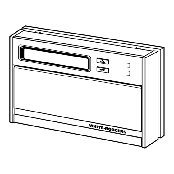
This wall-mounted, low voltage thermostat maintains
room temperature by controlling the operation of heating
and cooling systems. The user may program up to four
time/temperature settings per 24 hour period. The ther-
mostat stores independent heating and cooling programs
for each day of the week. The thermostat will store both
heating and cooling programs simultaneously. Three
®
"AA" Energizer
batteries will maintain the stored program
for approximately one year, if incoming power should fail.
If power failure is extensive and the program is lost, after
power restoration, the thermostat will automatically main-
tain a factory preprogrammed heating temperature of
64°F or a cooling temperature of 82°F.
If in doubt about whether your wiring is millivolt, line, or low
voltage, have it inspected by a qualified heating and air
conditioning contractor, electrician, or someone familiar
with basic electricity and wiring.
Do not exceed the specification ratings.
CONTENTS
Description ......................................................... 1
Precautions ........................................................ 1
Specifications ..................................................... 2
Installation .......................................................... 2
Operation ........................................................... 6
WHITE-RODGERS DIVISION
EMERSON ELECTRIC CO.
9797 REAVIS ROAD
ST. LOUIS, MISSOURI 63123-5398
R
7-Day Electronic Digital Thermostat
INSTALLATION INSTRUCTIONS
All wiring must conform to local and national electrical
codes and ordinances.
This control is a precision instrument, and should be
handled carefully. Rough handling or distorting compo-
nents could cause the control to malfunction.
To prevent electrical shock and/or equipment
damage, disconnect electric power to system at
main fuse or circuit breaker box until installation
is complete.
Do not use on circuits exceeding specified volt-
age. Higher voltage will damage control and
could cause shock or fire hazard.
Do not short out terminals on gas valve or pri-
mary control to test. Short or incorrect wiring will
burn out thermostat and could cause personal
injury and/or property damage.
Printed in U.S.A.
1F97W-51
DESCRIPTION
PRECAUTIONS
CAUTION
!
WARNING
!
PART NO. 37-5093B
Replaces 37-5093A
9531
Advertisement
Table of Contents

Related Manuals for White Rodgers 1F97W-51


Summary of Contents for White Rodgers 1F97W-51
-
Page 1: Table Of Contents
1F97W-51 7-Day Electronic Digital Thermostat WHITE-RODGERS INSTALLATION INSTRUCTIONS Operator: Save these instructions for future use! FAILURE TO READ AND FOLLOW ALL INSTRUCTIONS CAREFULLY BEFORE INSTALLING OR OPERATING THIS CONTROL COULD CAUSE PERSONAL INJURY AND/OR PROPERTY DAMAGE. DESCRIPTION This wall-mounted, low voltage thermostat maintains room temperature by controlling the operation of heating and cooling systems. -
Page 2: Specifications
SPECIFICATIONS ELECTRICAL DATA APPLICATIONS Electrical Rating: For use with: 17 to 30 VAC 50/60 Hz. • Standard heat/cool, heat-only, or cool-only sys- 0.05 to 1.5 Amps tems 1.5 Amps Maximum Total Load (All terminals • Electric heat systems combined) • Gas or oil fired systems Anticipation: •... -
Page 3: Replacement Installation
REPLACEMENT INSTALLATION TABLE 1. OLD THERMOSTAT IDENTIFICATION REMOVE OLD THERMOSTAT OLD THERMOSTAT THERMOSTAT TERMINAL IDENTIFICATION TYPE 1. Shut off electricity at the main fuse box until installa- Type tion is complete. Verify power is off with a voltmeter. 2. Remove the front cover of the old thermostat. With Type wires still attached, remove wall plate from the wall. - Page 4 NOTE CAUTION All wiring diagrams are for typical systems only. Refer to To prevent electrical shock and/or equipment equipment manufacturers’ instructions for specific sys- damage, disconnect electrical power at the main tem wiring information. fuse box or circuit breaker until installation is complete.
-
Page 5: Attach Thermostat To Subbase
From heating system CONNECT red jumper JUMPER wire (provided) WIRE THERMOSTAT SYSTEM NOTE Cooling Heating RED jumper wire (pro- System Relay System vided with thermostat) must be connected be- tween thermostat's 24 VAC 120 VAC From fan relay and RC terminals for pro- Neutral per thermostat operation From cooling system... -
Page 6: Operation
OPERATION SYSTEM CONFIGURATION Batteries 6-pin Connector ELECTRIC HEAT SYSTEMS NOTE For central electric heat systems where the blower is energized by a separate circuit through the fan relay (meaning that the fan turns on immediately on call for heat), clip wire W14 on the back of the thermostat (see fig. 10). -
Page 7: Cooling System
COOLING SYSTEM OPERATION LOCKOUT BYPASS OPTION CAUTION FOR QUALIFIED SERVICE TECHNICIANS’ USE ONLY. OPERATORS SHOULD NOT USE THIS FEA- To prevent compressor and/or property damage, TURE DUE TO POSSIBILITY OF EQUIPMENT OR if power to the compressor has been off or PROPERTY DAMAGE, OR PERSONAL INJURY. - Page 8 If you need further information about this product, please write to: WHITE-RODGERS Division of Emerson Electric Co. 9797 Reavis Road St. Louis, MO 63123-5398 ATTN: Technical Service Department...
Need help?
Do you have a question about the 1F97W-51 and is the answer not in the manual?
Questions and answers