
Subscribe to Our Youtube Channel
Related Manuals for White Rodgers Comfort-Set 1F97-391


Summary of Contents for White Rodgers Comfort-Set 1F97-391
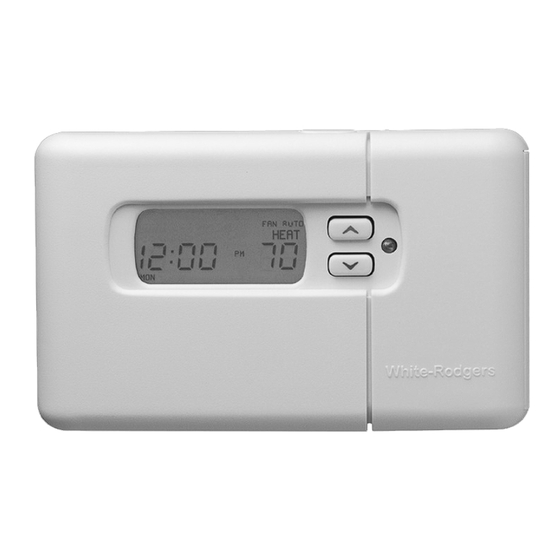
- Page 1 Thermostat/Humidifier Control Digital 7 Day Programmable ® Comfort-Set 90 Series P R E M I U M 1F97-391 Installation and Operating Instructions Retain for Future Use...
- Page 2 Easy, Menu-Driven Set-Up and Programming Premium options to customize the thermostat to fit your application.
- Page 3 INTRODUCTION Thank you for purchasing your new Comfort-Set 90 thermostat and humidifier control. White- Rodgers has been producing energy saving controls for over 60 years. We have been design- ing and producing the Comfort- Set family of electronic pro- grammable thermostats since 1982.
- Page 4 (99°F or 37°C maximum) The yellow indicator glows when the system is operating. This button (on top of the cover) lights the display. Used to initiate or review thermostat programming. Used with TIME /TIME to set the clock. Used to adjust the time backward, or to select the previous menu item.
- Page 5 B B B B B A A A A A TTER TTER TTER TTERY Y Y Y Y appears TTER when the thermostat is running on battery power only. CHECK ST CHECK ST CHECK ST CHECK ST...
-
Page 6: Installation And Configuration
SPECIFICATIONS SPECIFICATIONS SPECIFICATIONS Model 1F97-391 Model 1F97-391 Model 1F97-391 Model 1F97-391 7 Day Programming Model 1F97-391 ELECTRICAL D ELECTRICAL D ELECTRICAL DA A A A A T T T T T A A A A A ELECTRICAL D ELECTRICAL D... - Page 7 This thermostat is intended for use with a low voltage system. Do not use directly on a line voltage system unless an isolation relay/transformer is installed. Do not exceed the ratings shown in the Specifications section, preceding page.
-
Page 8: Remove Old Thermostat
Disconnect the wires from the old thermostat one at a time. DO NOT let the wires fall back into the wall. Install the new thermostat using the following procedures. - Page 9 AND PROGRAMMING AND PROGRAMMING AND PROGRAMMING AND PROGRAMMING Before the power is turned on, the thermostat must be configured to operate properly with the system. See CONFIGURATION on page 16 in this manual. Mounting screws Pull wires through this opening...
- Page 10 Figure 3 – Typical wiring diagram for heating only, single transformer system NOTE: Ensure that RED RH/RC jumper wire (provided with thermostat) is connected between thermostat's RH and RC terminals for proper operation with this system. HM1 W RH RC G...
- Page 11 LETTER IDENTIFICATION FOR WIRING DIAGRAMS Humidifier System Zone Valve Cooling System Fan Relay Heating System Installation/Configuration Jumper Wire TRANSFORMER 24 VAC Side 120 VAC Side Hot Side Neutral Side HEATING TRANSFORMER COOLING TRANSFORMER Jumper Wire (field-installed)
- Page 12 Figure 4 – Typical wiring diagram for heat only, cool only, & heat/cool single transformer system NOTE: Ensure that RED RH/RC jumper wire (provided with thermostat) is connected between thermostat's RH and RC terminals for proper operation with this system.
- Page 13 Figure 5 – Typical wiring diagram for heat only, three-wire, zone valve system Installation/Configuration NOTE: Thermostat must have batteries installed. NOTE: Ensure that RED RH/RC jumper wire (provided with thermostat) is connected between thermostat's RH and RC terminals for proper operation with this system. HM1 W RH RC G HM2 6...
- Page 14 From heating system From 24 VAC heating transformer From 24 VAC cooling transformer From fan relay From cooling system For humidifier wiring see pages 14-15. See page 9 for letter identification. Figure 6 – Typical wiring diagram for heat/cool, two-transformer system HM1 W RH RC G HM2 6...
- Page 15 From 24 VAC cooling transformer From fan relay From cooling system For humidifier wiring see pages 14-15. See page 9 for letter identification. Figure 7 – Typical wiring diagram for three-wire cooling system Installation/Configuration HM1 W RH RC G HM2 6...
- Page 16 NOTE: Two terminal choices (HM1 or HM2) are provided for humidifier control. When the humidity setting is higher than the room humidity: HM1 turns off the humidifier when the call for heat ends. HM2 powers the humidifier an additional 30 seconds after the call for heat ends to provide slightly more humidity output.
- Page 17 Relay 90-290Q or equivalent Figure 9 – Typical wiring diagram for 120V humidifier system Installation/Configuration HM1 W RH RC G From humidity system See page 9 for letter identification. HM2 6...
- Page 18 REQUIRES the thermostat to control the fan, find and cut the jumper lead labelled W914 (see fig. 10). This will allow the thermostat to energize the fan instantly on a call for heat. If you are unsure if the system...
- Page 19 Clip for remote sense 3-pin connector Clip for electric heat Installation/Configuration W914 W922 Figure 10 – Jumper locations...
- Page 20 CONFIGURATION MENU TION MENU TION MENU The configuration menu allows you to set thermostat operating characteristics to your system or personal requirements. To enter the menu, press TIME menu options. Press options. We recommend that other options be set by the installer.
- Page 21 TIME TIME TIME TIME TIME TIME TIME TIME PROGRAM NOTE: COMP LOCK OFF permanently defeats the compressor lockout. Turn this feature off only if the system already provides for compressor short-cycle protection. 0˚F 5 LO to 5 HI (˚F) ˚C BEEP (ON) REMT SEN...
- Page 22 This option allows a selection of a fan- on delay of 1 to 5 seconds on a call for cool and 1 to 127 seconds of fan-off delay after the thermostat has satisfied the call for cool. A short delay to allow the A-coil to cool off before the fan turns on may be preferred.
- Page 23 OPTIONAL REMOTE OPTIONAL REMOTE OPTIONAL REMOTE OPTIONAL REMOTE OPTIONAL REMOTE TEMPERATURE SENSE TEMPERATURE SENSE TEMPERATURE SENSE TEMPERATURE SENSE TEMPERATURE SENSE An optional remote sensor (part # F145-1328) can be attached to this thermostat and may be wired as far...
-
Page 24: Fan Operation
CHECK CHECK THERMOST T OPERATION T OPERA away as 300 feet. The thermostat will use the temperature in the remote location as its room temperature display. This is an excellent feature if the thermostat is in a poor location for... - Page 25 RESETTING THERMOSTAT RESETTING THERMOSTAT The thermostat can be reset back to factory default programs and configu- ration options. Removing power from the thermostat will not reset it to the default settings. Before resetting the T OPERA T OPERA T OPERA T OPERATION (cont’...
- Page 26 (Bypassing the Pro o o o o g g g g g r r r r r am) (Bypassing the Pr (Bypassing the Pr (Bypassing the Pr Your Comfort-Set 90 thermostat can be used to control temperature manually (without programming). For manual operation, press...
- Page 27 9. If you program Monday the first time you press PROGRAM VIEW will be copied to the rest of the week. To program the other days of the week press /DAY until you reach the ADV. day you wish to change and follow Steps 10, 11 &...
- Page 28 6:00 AM 70 F (21 C) 6:00 AM 70 F (21 C) 6:00 AM 70 F (21 C) 6:00 AM 70 F (21 C) 6:00 AM 70 F (21 C) 6:00 AM 70 F (21 C) 6:00 AM 70 F (21 C) Morning (MOR) Day (DAY) Evening (EVE)
- Page 29 7 Day Sample COOL Program Schedule (Shows factory programming) 6:00 AM 78 F (25 C) 6:00 AM 78 F (25 C) 6:00 AM 78 F (25 C) 6:00 AM 78 F (25 C) 6:00 AM 78 F (25 C) 6:00 AM 78 F (25 C) 6:00 AM 78 F (25 C)
- Page 30 Morning (MOR) Day (DAY) Evening (EVE) Night (NHT) Start Time Temperature 7 Day Personal HEAT Program Schedule...
- Page 31 Morning (MOR) Day (DAY) Evening (EVE) Night (NHT) Start Time Temperature 7 Day Personal COOL Program Schedule Programming...
- Page 32 Programmable Vacation Time Temp ------------------------ 33 Daylight Savings Time Button ---- 33 Battery Back-up --------------------- 33 Keypad Lockout --------------------- 34 Thermostat Start-up after Power Loss ------------------------ 34 Compressor Short Cycle Protection -------------------------- 35 Air Filter Change-Out Indicator --- 35 System and Thermostat...
- Page 33 The large numbers and letters on your LCD screen make it easy to see. In low light conditions, press the button on top of the thermostat and the display will light up for three seconds. For ten minutes after pressing the light button, pressing any other button will light the display for ten seconds.
- Page 34 In cooling, the thermostat uses 15 minutes per °F. EXAMPLE: If the temperature in the room is 65°F and the thermostat is programmed for 70°F at 7 AM, the thermostat will start approximately 25 minutes early. The difference between the room temperature (65°F) and the...
- Page 35 The VACATION mode allows you to program the thermostat to hold a constant temperature for 1 to 29 days. At the end of the day and time you select, the thermostat will return to normal program operation.
- Page 36 85°F (29°C). A total loss of power will occur when you lose 24 VAC power to the thermostat, and you have no battery backup. If this happens, the thermostat display will go blank in about one minute after power loss.
- Page 37 SYSTEM if the room temperature does not rise within two hours of the call for heat. After two hours the thermostat will quit calling for heat for one minute (this allows some furnaces to reset) and call for heat again. It will...
- Page 38 • One of the buttons is stuck down or in. Check buttons, make sure nothing is pushing them in. • The thermostat sensor is not functioning. If using a remote sensor, check connections, wiring and power. • The humidity sensor is not function- ing.
- Page 39 This is to prevent the interior windows/walls from reaching the dew point where water condenses on surfaces. To achieve automatic humidity reduction, the thermostat lowers the humidity when furnace cycles are long. When the furnace runs shorter cycles, it increases humidity.
- Page 40 (not blinking) indicates a loss of power (24 volts) from the heating and cooling equipment What does it mean? to the thermostat, or that the thermostat is operating on battery power only. To bypass the program and operate the thermostat manually press the MODE SY 3.
- Page 41 Normally the blower will turn off within a few minutes after the call for heat or cool. The blower running after the system shuts off may indicate (1) the thermostat is set to F F F F F AN keep running after the system...
- Page 42 OFF. This will not affect your thermostat’s programming in any way. To SYSTEM STEM STEM button until HEA STEM STEM 1F97-391 1F97-391 will retain the last program entered indefinitely without power or batteries. 1F97-391 1F97-391 SYSTEM STEM button until the STEM STEM...
- Page 43 FAQs 1F97-391 Visit our website at www.white-rodgers.com for operating manuals. 11. How can I get an extra copy of the Operating Manual for my thermostat? 12. What do I do if my Contact a Local Heating & Cooling service person or visit our website at www.white-rodgers.com to consult our “Where to Buy”...
-
Page 44: Troubleshooting
STEM Press the SY STEM and raise temperature above room temperature. Verify thermostat and system wires are securely attached. Many furnaces have safety devices that shut down when a lock-out condition occurs. If the heat works intermittently, contact the furnace manufacturer or... - Page 45 Same procedure as Diagnostic for No Heat condition except set the thermostat to Cool and lower the setpoint below the room temperature. There may be up to a 5 minute delay before the thermostat clicks in Cooling. DOWN Troubleshooting...
- Page 46 No bare wire should stick out from under terminal screws. Try resetting the thermostat as described in previous Corrective Actions. Also, if the FAN switch is set to the ON position, the blower fan will cycle continuously whether the heating or cooling system is running, move FAN switch to the AUTO position.
- Page 47 SYMPTOM POSSIBLE CAUSE Blank Display and/or Keypad 1. Voltage spike or static Not Responding discharge. 2. Battery change required. How do I change the room Humidity display? CORRECTIVE ACTION Replace batteries and check heat/cool system for proper operation. If a voltage spike occurs, use the Reset Operation by pressing F F F F F AN the temperature DO DOWN...
- Page 48 Fan Control, Programmable -------- 33 Factory Preprogrammed ------------ 31 FAQs ---------------------------------- 38 FEATURES -------------------------- 30 Humidifier Maintenance Indicator 36 INTRODUCTION -------------------- 2 Thermostat Buttons --------------- 2 Display ------------------------------ 3 Keypad Lockout --------------------- 34 Liquid Crystal Display -------------- 31 Operation Manual ----------------------------- 24...
- Page 49 Index...
- Page 50 NOTES...
- Page 51 NOTES...
- Page 52 PART NO. 37-6459A The Emerson logo is a White-Rodgers is a division trademark and service mark of Emerson Electric Co. 0339 of Emerson Electric Co. Printed in U.S.A.
Need help?
Do you have a question about the Comfort-Set 1F97-391 and is the answer not in the manual?
Questions and answers
Does this use batteries?
Yes, the White Rodgers Comfort-Set 1F97-391 uses batteries, and it is recommended to change them once a year or when "CHECK BATTERY" is displayed.
This answer is automatically generated