Table of Contents
Advertisement
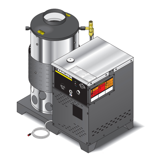
OPERATOR'S MANUAL
HDS NG 4.5/22 Ea St - 1.575-715.0
HDS NG 5.0/30 Eb St - 1.575-717.0
To locate your local Kärcher Commercial Pressure Washer Dealer nearest you,
visit our web page at www.karchercommercial.com
98001600-2
HDS NG 3.5/30 Ea St - 1.575-719.0
HDS NG 5.0/30 Ec ST - 1.575-721.0
®
9.800-160.0
Advertisement
Table of Contents
Troubleshooting


Need help?
Do you have a question about the HDS NG 4.5/22 Ea St - 1.575-715.0 and is the answer not in the manual?
Questions and answers