Table of Contents
Advertisement
Quick Links
Download this manual
See also:
Operating Manual
Advertisement
Table of Contents

Related Manuals for mcmurdo F1 DSC


Summary of Contents for mcmurdo F1 DSC
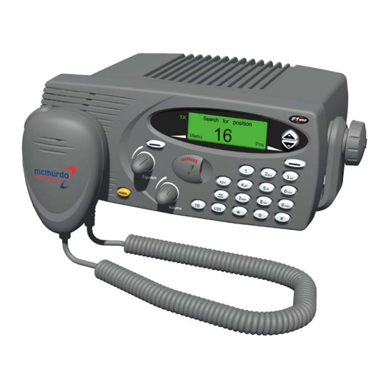
- Page 1 McMurdo F1 DSC Marine VHF Radio with DSC Installation Manual...
- Page 2 The F1 DSC Radiotelephone is easy to operate and gives the user high quality effective radio communication to other ships as well as to shore based stations.
- Page 3 Maintenance The F1 DSC Radiotelephone is an essential part of the ship’s emergency system. As the radio is a vital component for the safety of the ship and its crew it is very important to maintain the radio and its installation to a very high standard. The design of the radio ensures that maintenance can be kept to a minimum, however it is good practice to perform a functional check at least once every month.
- Page 4 +55°C. Do not install (or use) the transceiver in areas which exceed this range. CAUTION: The F1 DSC radio is water resistant to international standards. However, if either the transceiver or microphone casing is damaged (e.g. due to heavy impact) then the sealing cannot be guaranteed.
- Page 5 IMPORTANT: Normal users of the transceiver should be trained, licensed operators, but this rule is waived in an emergency and any person can transmit a Distress Call. Please refer to the F1 DSC Radiotelephone Operation Manual for full radio operating procedures.
-
Page 6: Table Of Contents
Connection of GPS for position information ............14 Connection of fist mike to the rear D-sub connector (socket) ......15 Connection of fist mike to the D-sub plug ............16 Connection of antenna..................17 Performance check ................19 Technical Specifications..............20 McMurdo Limited Product Warranty..........22... -
Page 7: Installing The Mmsi Number
Installing the MMSI number To ensure full performance of the F1 DSC Radiotelephone it is essential that the MMSI number is installed in the radio. WARNING: If no MMSI number is installed the radio will be unable to transmit a DSC call including the transmission of a DSC distress alert. - Page 8 (correct) the MMSI number once more only. However, after one hour from the time of entering the first MMSI number the radio will inhibit changing the MMSI number. If this happens, the radio must be returned to McMurdo (via the supplier) for reprogramming to allow entering another MMSI number.
-
Page 9: Mounting Options
Mounting options Introduction To ensure high performance of the F1 DSC Radiotelephone it is very important that the installation guidelines described in this book are followed. When installed make sure the radio is fixed to a solid surface. The mounting surface to which the radio is fixed must be as solid and as free of vibrations from the ship's engine or other vibration generating sources as possible. -
Page 10: Tabletop Or Ceiling Installation
Tabletop or ceiling installation The F1 DSC Radiotelephone can be mounted on top of a table or on the ceiling. The supplied bracket is used to mount the radio in these positions. The mounting bracket is supplied with 6 installation screws; it is recommended to use all 6 screws. - Page 11 Page 5...
-
Page 12: Bulkhead Or Panel Mounting
Bulkhead or panel mounting For bulkhead or panel mounting of the F1 DSC Radiotelephone two mounting kits are available: a flush mounting kit and a simple bulkhead/panel mounting kit. Flush mount kit (kit number 84-412) The flush mounting kit when installed properly provides a watertight installation of the radio in a bulkhead or instrument panel. - Page 13 Page 7...
-
Page 14: Bulkhead And Instrument Panel Mounting Kit (Kit Number 84-413)
Use of the bulkhead and instrument panel mounting kit is a simple way to build in the F1 DSC Radiotelephone. Screws are provided with this mounting kit. Before the hole is cut in the bulkhead or the instrument panel, make sure that the space behind the bulkhead or instrument panel is sufficient to accommodate the radio and connecting cables. -
Page 15: Drilling Guides
Drilling guides Table top bracket drilling guide Page 9... - Page 16 Flush mount kit cutting guide Bulkhead and instrument panel mount kit cutting guide A full size template is provided with each mount kit. Page 10...
-
Page 17: Electrical Connections
Electrical connections It is recommended that this guideline for electrical connection of the F1 DSC Radiotelephone is followed as carefully as possible. A careless installation is likely to degrade performance of the radio and cause difficulties for the operator. Most radio... - Page 18 Table 1 Recommended wire size for connection of power supply Supply From Wire mm Maximum length 12 VDC Battery F1 DSC 1.5m 12 VDC Battery F1 DSC 3.0m Page 12...
-
Page 19: Connection Of External Loudspeaker
Connection of external loudspeaker An external loudspeaker may be connected to the F1 DSC Radiotelephone. The external speaker is connected to the two wires in the power plug intended for this use. If it is necessary to extend the wires to the external loudspeaker, wire dimensions as specified should be used. -
Page 20: Connection Of Gps For Position Information
The information transmitted from a GPS uses a standard interface, designated NMEA 0183. The F1 DSC Radiotelephone can be connected to this GPS interface directly via the two wires to the 15 pin D-sub connector. -
Page 21: Connection Of Fist Mike To The Rear D-Sub Connector (Socket)
When the flush mounting kit is used for bulkhead or instrument panel installation of the F1 DSC Radiotelephone it is necessary to connect the fist mike to the D-sub connector at the rear of the radio. A wire loom is provided to connect the fist mike to the rear of the radio. -
Page 22: Connection Of Fist Mike To The D-Sub Plug
Connection of fist mike to the D-sub plug If for a particular installation the attachment of the fist mike to the front of the radio is inconvenient, the mike can be connected to the D-sub connector at the rear of the radio, as shown. -
Page 23: Connection Of Antenna
Connection of antenna The antenna and the antenna cable are a very important part of the radio installation and it is therefore very important to use good quality materials. The antenna must be marked as a VHF antenna covering at least the frequency band from 153MHz to 163MHz. - Page 24 Table 4 Coax cable signal losses Typical cable losses for two common types of coaxial cable. Cable type Cable loss per meter for VHF channels RG 58 2.0 dB/10 meter cable RG 214 0.8 dB/10 meter cable Line of sight As a general rule the VHF communication range is the same as the line of sight distance, which means that the receiver antenna must be able to see the transmitter antenna.
-
Page 25: Performance Check
10. When acknowledgement is received, call the coast station on the suggested working channel to confirm that the test has been carried out successfully. For instructions on how to use the F1 DSC Radiotelephone and set up a DSC call see the Operation Manual. -
Page 26: Technical Specifications
Technical Specifications The McMurdo F1 DSC Radiotelephone conforms to all relevant international requirements agreed for a VHF DSC class D radiotelephone by ETSI, IEC, ITU and IMO. These specifications include ETSI 301 025, IEC 62238, IEC 60945, ITU-R M.493-10 and ITU-R M.541-8... - Page 27 Transmitter RF output power High 25W +0dB, –2dB 1W +0dB, –3dB Adjacent ch. power < 70dBc Spurious radiation < 0.25mW Cabinet radiation < 0.25mW AF response +6dB/octave Signal/noise ratio > 40dB DSC Facilities DSC operation According to Rec. ITU-R M.541-8 DSC protocol According to Rec.
-
Page 28: Mcmurdo Limited Product Warranty
(or part) in question free of charge, or at McMurdo Limited's sole discretion to refund to the buyer the price of the product (or a proportional part of the price). McMurdo Limited shall not be liable to a buyer who is not a consumer for any other loss or damage (whether indirect, special or consequential loss of profit or otherwise) costs, expenses or other claims for compensation which arise out of or in connection with this product. - Page 29 Declaration of Conformity The Declaration of Conformity is provided as a separate document. Page 23...
- Page 30 Notes Page 24...
- Page 31 Page 25...
- Page 32 Record Serial No.: MMSI: Date of Purchase: Dealer Stamp McMurdo Ltd Silver Point Airport Service Road Portsmouth Hampshire United Kingdom PO3 5PB A member of Chemring Group PLC www.mcmurdo.co.uk 84-783 Issue 1 Page 26...
Need help?
Do you have a question about the F1 DSC and is the answer not in the manual?
Questions and answers