Table of Contents
Advertisement
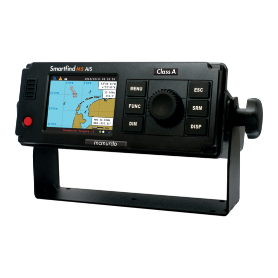
Smartfind M5 Class A / Inland AIS
Installation and Maintenance Manual
1
General Information
Disclaimer
i.
The information and illustrations contained in this publication are to the best of our
knowledge correct at the time of going to print. We reserve the right to change
specifications, equipment, installation and maintenance instructions without notice as part
of our policy of continuous product development and improvement. No part of this
publication may be reproduced, stored in a retrieval system or transmitted in any form,
electronic or otherwise without permission in writing from Orolia Ltd. No liability can be
accepted for any inaccuracies or omissions in the publication, although every care has
been taken to make it as complete and accurate as possible.
This manual is applicable for McMurdo Smartfind M5 manufactured after June 2014.
Safety Warning
ii.
It is important to know that AIS is designed for the purpose of anti-collision and
serves as a complement to navigation. It is not the absolute navigational
equipment and does not replace any navigational system installed on board.
Any AIS device cannot guarantee monitoring and receiving signals from all
vessels in the surroundings unless those vessels are equipped with AIS devices.
The coastline map in this transponder is neither verified nor approved by
Hydrographic Authorities. It is not an Electronic Chart System and therefore
should not be used for navigation. The information provided by the coastline map
is for reference only and should be used together with other navigation sources
and devices.
ELECTRICAL SHOCK HAZARD
Improper disassembly or modification could cause electrical shocks, fire, or
personal injury. Contains no user-serviceable parts.
RADIO FREQUECY RADIATION HAZARD
The AIS transponder emits low levels of radio frequency radiation when
transmitting; to avoid health hazards from excessive exposure to RF energy, all
persons must be at least 3 metres separation radius/horizontally or 1m vertically
away from the antenna.
CORRECT POWER SOURCE
An incorrect power source will damage the equipment and may even result in a
fire. Ensure that the correct power source is provided at all times.
AVOID DIRECT CONTACT WITH RAIN OR SPLASHING WATER
Electrical shock or fire could be resulted if water leaks into the equipment.
AVOID USING CHEMICAL SOLVENTS TO CLEAN THE CASE
As some solvents can damage the case material.
RADIO LICENCE
The AIS transponder is a maritime radio transmitter. Some administrations may
require that the user holds a valid radio licence to cover its ownership and use.
i
Advertisement
Table of Contents

Subscribe to Our Youtube Channel
Related Manuals for mcmurdo SMARTFIND M5


Summary of Contents for mcmurdo SMARTFIND M5
- Page 1 This manual is applicable for McMurdo Smartfind M5 manufactured after June 2014. Safety Warning It is important to know that AIS is designed for the purpose of anti-collision and serves as a complement to navigation.
- Page 2 Declaration of Conformity viii. Hereby Orolia Ltd declares that the Type Z601 (McMurdo Smartfind M5) is in compliance with the essential requirements and other relevant provisions of the Marine Equipment Directive (MED) 96/98/EC. A copy of the Declaration of Conformity can be obtained on-line from: www.mcmurdomarine.com/documents...
-
Page 3: Table Of Contents
Table of Contents 4.7.9 Friend Ships ........................... 46 ........................... 47 ETTING 4.8.1 Own Ship ..........................47 4.8.2 Voyage ........................... 48 4.8.3 CPA/TCPA ..........................49 WHAT IS AIS? ......................1 4.8.4 SET MMSI/IMO/ENI ....................... 49 SYSTEM OVERVIEW ....................2 4.8.5 Retry Times ..........................50 4.8.6 AIS Mode .......................... -
Page 4: What Is Ais
1 WHAT IS AIS? ................. 93 ONITORING OF YSTEM UNCTIONS AND NTEGRITY VSWR E ...................... 93 NTENNA XCEEDS IMIT ...................... 93 ETECTION OF ALFUNCTION ...................... 93 ETECTION OF ALFUNCTION The Automatic Identification System (AIS) is a Very High Frequency (VHF) radio broadcasting APPENDIX (C) ........................ -
Page 5: System Overview
(supplied in the package). The unit can also interface external navigation and presentation systems that support IEC 61162-1 related sentences. It is also capable for connection to Long Range system like Inmarsat C. The Smartfind M5 supports both IMO and Inland AIS which is configurable by the software. -
Page 6: Installation
3 INSTALLATION 3.3 RF Cable Requirements The following RF cables are recommended to install the Smartfind M5. 3.1 Equipment in the Box VHF Antenna Cable Type: 5D-FB or RG214 or equivalent The standard supply in the package includes the following items. Please contact your local Connector: SO-239 (Male) representative if any item is missing. -
Page 7: Mounting
Figure 3 GPS Antenna location 3.6 Mounting Smartfind M5 Use the following guidelines to check the installation location for your AIS transponder: The AIS transponder should be mounted in a location that is accessible and readable to user at all time. -
Page 8: Mounting Junction Box
Mounting Junction Box (1) The Pilot Plug device provides connecting interface to pilots and other mariners to connect their own PC or other portable device to the transponder on board. Smartfind M5 Pilot Plug Figure 6 Mounting Junction Box (1) - Page 9 Connecting to the Junction Box 3.7 External Connectors (Transponder Main Unit) Use the following guidelines to connect the Pilot Plug to the Junction box. Please refer to section 3.8 External Connectors (Junction Box). Frame Ground To Transponder Main Unit Figure 8 External Connectors (Main Unit) Pilot plug NAME...
- Page 10 3.8 External Connectors (Junction Box) PILOT_IN Pilot Plug port Input Ground PILOT_IN A Input A To Transponder Main Unit PILOT_IN B Input B Pilot Plug DISP PILOT_OUT DGPS Blue Sign Sensors 1~3 Output Ground PILOT_OUT A Output A Termination PILOT_OUT B Output B switches Alarm normally...
-
Page 11: Extension Cable
The following initial configuration is required: 3.9 Connecting Extension Cable 1. Setup 1: MMSI should be correctly programmed. Use the 37-pin- extension cable (1.8M) provided in the package connect Smartfind M5 to the Built-in Test junction box. Power…………………..…….…………[PASS] Flash..…………………..…….…………[PASS]... -
Page 12: Operation
4 OPERATION A. Setup call sign, ship name, ship type, external/internal GPS antenna position in OWN SHIP. 2013/01/17 07:18:11 4.1 Panel Description MENU MAIN MENU SHIP SETTING MESSAGES NAV. STATUS OWN SHIP VOYAGE SHIP SETTING CPA/TCPA TRANSCEIVER SYS CONFIG SET MMSI/IMO/ENI DIAGNOSTICS RETRY TIMES AIS MODE... -
Page 13: Status Bar
4.1.1 Status Bar 4.1.2 Transmission and Reception Bar The status bar constantly indicates Date (YYYY/MM/DD), Time, GPS status, ALR, and SRM. The Transmission & Reception bar constantly displays real time status of transmissions and receptions on any display modes. The 3 default displayed messages are received AIS targets, dangerous targets, and Tx power level. -
Page 14: Modes
4.2 Display Modes For quick access, users can rotate display modes by simply pressing the DISP button. Shows the GPS satellite current usage GPS Satellite status Display Mode Screen Shot Purpose Information (Refer to section 4.12 GPS Status) Display all targets on basic coastline map Coastal View (Refer to section 4.2.2 Coastal View) Orolia Ltd. -
Page 15: Coastal View
4.2.2 Coastal View Lost Signal Colour: Black / Red Cross Target If reception of an AIS target has ceased over 10 minutes, a “X” will be displayed over it. The target will disappear from the Radar View after its 2013/01/17 07:18:11 reception has ceased for one hour. -
Page 16: Radar View
4.2.3 Radar View 4.3 Entering Text The knob on the front control panel is used for entering and editing text. The figures below show 2013/01/17 07:18:11 the text entering procedures. Own ship Orolia Ltd.: information A. Turn the knob to traverse the menu items up or down. Once selected, press the knob to 1°13’02”N select the item for text entering. -
Page 17: Entering
4.4 Menu Tree Overview Press MENU button to enter MAIN MENU. Please note inland menus, Inland Messages and Inland Settings, are only available when the unit operates under inland mode. MESSAGES INBOX SRM (4.5.1) Select a character position OUTBOX SRM (4.5.2) BROADCAST SRM (4.5.3) Turn knob to move Press to start... -
Page 18: How To Access And Use Main Menu
4.4.1 How to access and use MAIN MENU 4.4.2 Menu Item Brief Description 2013/01/17 07:18:11 MESSAGES MENU INBOX SRM Log of safety related messages (SRM) received MAIN MENU OUTBOX SRM Log of safety related messages (SRM) sent MESSAGES NAV. STATUS BROADCAST SRM Send SRM. -
Page 19: 4.5 Messages
4.5 Messages INLAND SETTING VESSEL DATA SET. Configure Vessel data The M5 features SRM alert pop-ups that can appear any time during operation. When a SRM (Safety Related Messages) from other AIS equipped vessels is received, you can either read and ETA SETTING Configure ETA acknowledge it by pressing the knob or ignore the message by press ESC. -
Page 20: Outbox Srm
4.5.2 Outbox SRM 4.5.4 Addressed SRM You can read all sent SRM messages under OUTBOX. Turn the knob to traverse the message list ADDRESSED SRM means a SRM addressed to a certain MMSI number which can be selected and highlight your choice. Read the message content by pressing the knob. from the target list or input manually. -
Page 21: Long Range Srm
4.5.5 Long Range SRM 4.6.1 ETA/RTA Inbox When the transponder is connected to a long range communication system via the long range The received messages of ETA (RFM21) and RTA (RFM22) can be read in the ETA/RTA Inbox. communication port then long range interrogations may be received. These are requests for Turn the knob to traverse the message list and highlight your choice. -
Page 22: Pob Outbox
4.6.5 Create POB Message After ETA (RFM21) transmitted, if no RTA (RFM22) is received within 15 minutes, transponder will transmit ETA (RFM21). In this submenu users can compose number of person on board (RFM55/IFM16) messages. After the addressee is selected, you can configure the ETA message. Number of person on-board can be configured in Inland Setting 4.9.3. -
Page 23: Water Level
4.6.7 Water Level 4.7.1 Own Ship This submenu displays received water level (RFM24) messages from base station to ship about This option displays the full information on your ship, including both dynamic and static data. local water level information. Turn the knob to change between dynamic and static information. 2013/01/17 23:27:10 2013/01/17 23:27:10 Static data and Dynamic Data... -
Page 24: Ais Targets
4.7.2 AIS Targets Adding Friend Ship In the list, press FUNC button will open the pop-up window with the question whether the selected vessel should be added to your FRIEND SHIP list, or to sort the list according to vessels’ MMSI, This option displays all received AIS information of other vessels including dynamic and static distance, or direction. -
Page 25: Region List
4.7.3 Region List 4.7.4 Alarm List The region list displays all saved region areas. Turn the knob to traverse the list. Press the knob The M5 features SART/MOB alarm that can appear any time during operation. When SART/MOB enables you to read the highlighted region information. message is received, the icon will appear in the status bar with beeping sounds from the beeper. -
Page 26: Alarm History
4.7.5 Alarm History 2013/01/17 22:43:39 SENSOR STATUS This submenu lists all recorded alarm and its time of occurrences. POSITION STATUS EXT. GNSS Position with RAIM 2013/01/17 07:18:11 2013/01/17 22:44:22 <= 10 m MENU ALARM HISTORY UTC STATUS LOST MAIN MENU ---- ID -- Text ----------------------DATE-- TIME- COG STATUS EXT. -
Page 27: Mob List
4.7.8 MOB List 4.8 Ship Setting This menu list provides access to settings that are required during installation of the transponder. With the setup of MOB list, MOB can be easily traced by the person’s name not just by the MMSI There are a total of 5 submenus. - Page 28 4.8.2 Voyage 4.8.3 CPA/TCPA 4.8.2.1 SOLAS Mode In this submenu the closest point of approach (CPA) and time to CPA (TCPA) can be set. The vessels with insufficient CPA and TCPA will be displayed in the dangerous list (see 4.7.7) and on 20 13/01/17 22:43:39 20 13/01/17 22:43:39 coastal and radar view.
- Page 29 4.8.6 AIS Mode For SOLAS vessels, the MMSI number can be entered in a valid range which is indicated on the input screen. To save the settings, press MENU or ESC and the system will ask whether the changes should be saved. Select OK to save or CANCEL to discard and return to main menu. Here you can configure the transponder to operate in SOLAS or INLAND mode.
- Page 30 4.9.1 Vessel Data Setting To save the settings, press MENU or ESC and the system will ask whether the changes should be saved. Select OK to save or CANCEL to discard and return to main menu. Inland related vessel data can be set in this submenu: 4.9.3 Number of Person ...
- Page 31 4.10 Transceiver 4.11.1 Customize Customize provides personalization settings: The submenu allows the users to switch on or off the transmission and change the supplied voltage of the GPS antenna between 3.3V and 5V. Dimmer Level - brightness setting from 1 (low) to 100 (high) ...
- Page 32 4.11.3 Map Calibration 4.11.5 Factory This section is password protected and can only be accessed using the password (see 4.11.6). This setting offers user functions to calibrate map data. Turn knob to select either latitude or After entering the password, the system will ask for your confirmation. Press knob to confirm your longitude to offset.
- Page 33 4.11.7 Long Range Setting 4.11.9 Destination Table Setting This option provides user choices to auto-response remote interrogation and settings of the Save up to 10 destinations. Use rotary knob to traverse text and to modify. Press Menu to save response information. changes.
- Page 34 4.12 Diagnostics 2013/01/17 22:43:39 This submenu provides users to check system statuses. There are a total of 8 check options. Strength of GPS 2013/01/17 07:18:11 GPS Satellite Satellite Signal MENU location Signal MAIN MENU DIAGNOSTICS MESSAGES SYSTEM ON/OFF NAV. STATUS Own Ship MEMORY TEST SHIP SETTING...
- Page 35 2013/01/17 22:43:39 Channel Bandwidth VERSION Sensitivity < -107 dBm @ BER < 10 PRODUCT Smartfind M5 AIS Class A Spurious Response Rejection 70 dB for signal @ -104 dBm; BER FIRMWARE V1.0.6.33 Blocking 84 dB for signal @ -104 dBm; BER COMPANY Orolia Ltd.
- Page 36 5.4 GPS Receiver (Internal) Alarm Output Relay contact 5.9 Environmental Receiving Channels 50 channels Tracking & Navigation -159 dBm Operating Conditions IEC 60945 “protected” category Sensitivity Operating Temperature -15°C ~ 55°C Reacquisition Sensitivity -159 dBm Operating Humidity 95% RH at 40°C <...
- Page 37 5.12 NMEA 2000 PGN Information 6.1 Smartfind M5 Transponder Main Unit The following table is a list of the NMEA 2000 messages supported by the Smartfind M5 unit. The “Transmit” PGNs information includes “Own ship” + “Received AIS information from other ships”.
- Page 38 Back (size: mm) 6.2 Junction Box Bottom (size: mm) 6.3 Extension Cable 6.4 Mounting Template (not to scale)
- Page 39 7 TROUBLESHOOTING 6.5 GPS Antenna Use the following guide to perform simple troubleshooting in case the transponder is not function accordingly. Symptom Possible Cause Solution Faulty connector to power Check power connection Transponder cannot power Polarity reverse Check power connection Power supply current too Check power supply Unit not powered up...
- Page 40 8 ABBREVIATIONS Multi-functional Satellite Minimum Keyboard and Display MSAS Augmentation System National Marine Electronics Navigation NMEA Terms of abbreviations: Association Nautical Mile Acknowledgement AtoN Aid to Navigation Output Automatic Identification System AUTO Automatic Alarm Auxiliary Presentation Interface Antenna Receiver Autonomous Integrity RAIM Rate of Turn BIIT...
- Page 41 IEC 61162-2 Data Interface IMPORTANT The Smartfind M5 Class A AIS Transponder provides 2 types of IEC 61162-2 data interfaces for Orolia Limited warranty registration user applications. The first interface type includes 3 input-only sensor data ports and the second Congratulations on purchasing your Smartfind M5.
- Page 42 Presentation Interface of Smartfind M5 A.1.2 Bidirectional Data Ports The schematic of bidirectional data port is shown in Figure A2. The schematics includes an isolated full duplex RS-485 transceiver IC (Texas Instrument ISO3080) which is used as the main component to handle both data input and output from external data source. The transceiver IC is isolated from external input.
- Page 43 Supported IEC 61162 Data Sentences Interpretation of Input Sentences Data Port Input Sentences Output Sentences A.5.1 ABM – AIS Addressed Binary and Safety Related Message This sentence supports ITU-R M.1371 Messages 6, 12, 25, 26 and provides an external Sensor 1 DTM, GNS, RMC, VBW, HDT, HDG, application with a means to exchange data via an AIS transponder.
- Page 44 A.5.3 ACK – Acknowledge Alarm A.5.6 BBM – AIS Broadcast Binary Message This sentence is used to acknowledge an alarm condition reported by a device. This sentence supports generation of ITU-R M.1371 binary messages 8, 14, 25, and 26. This provides the application with a means to broadcast data, as defined by the application only.
- Page 45 A.5.9 GBS – GNSS Satellite Fault Detection A.5.12 GNS – GNSS Fix Data This sentence is used to support receiver autonomous integrity monitoring (RAIM). Fix data for single or combined satellite navigation systems (GNSS). This sentence provides fix data for GPS, GLONASS, possible future satellite systems and systems combining these.
- Page 46 A.5.14 HDG – Heading, Deviation and Variation A.5.18 OSD – Own Ship Data Heading (magnetic sensor reading), which if corrected for deviation will produce magnetic Heading, course, speed, set and drift summary. Useful for, but not limited to radar/ARPA heading, which if offset by variation will provide true heading. applications.
- Page 47 A.5.21 SPW - Security Password Sentence Status , ground speed, A = data valid, V = data invalid This sentence can be used for authentication. For this purpose the sentence has to be Stern transverse water speed , knots ignored applied before the protected sentence (for example EPV, SSD).
- Page 48 Interpretation of Output Sentences A.5.28 PAMC, DBG – Proprietary Sentences, Debug The proprietary sentences are additional sentences only applicable to this product. Its main A.6.1 ABK – AIS Addressed and Binary Broadcast Acknowledgement usage is for enabling testing mode and parameter settings. This sentence is used for configuration.
- Page 49 A.6.3 ALR – Set Alarm State A.6.6 LR2 – AIS Long-Range Reply Sentence 2 Local alarm condition and status. This sentence is used to report an alarm condition on a The LR2-sentence contains the information items requested by the “B, C, E and F” device and its current state of acknowledgement.
-
Page 50: Monitoring Of System Functions And Integrity
Number of fill-bits Detection of Rx Malfunction The Smartfind M5 also has 3 built-in lock detectors (high active) to monitor each local oscillator (PLL circuit) of receiver channel 1, channel 2, and channel 70 respectively. If the operation of PLL circuit becomes abnormal, a logic low level will be sent from the lock detector to notify the system. -
Page 51: Installation And Maintenance Record
APPENDIX (C) Connected Sensors and Devices Installation and Maintenance Record Connected Port Equipment Model Number The following installation record should be completed and retained on board the vessel for Sensor 1 maintenance records. Sensor 2 Vessel Information Vessel Name Flag State Sensor 3 IMO Number MMSI Number... -
Page 52: Software Revisions
Software Revisions The transponder is delivered with software version according to the following table which is to be filled in and maintained either by manufacturer, distributor, dealer, or Installation Company. When software update is done, the new software (firmware) version can be identified through MKD at MENU/DIAGNOSTICS/VERSION (please refer to section 4.10.10 in the manual).
Need help?
Do you have a question about the SMARTFIND M5 and is the answer not in the manual?
Questions and answers