Table of Contents
Advertisement
Quick Links
Advertisement
Table of Contents

Subscribe to Our Youtube Channel
Related Manuals for mcmurdo Smartfind M5


Summary of Contents for mcmurdo Smartfind M5
- Page 3 Smartfind M5 Class A / Inland AIS Installation and Maintenance Manual...
- Page 4 This manual is applicable for McMurdo Smartfind M5 manufactured after August 2021. Safety Warning It is important to know that AIS is designed for the purpose of anti-collision and serves as a complement to navigation.
- Page 5 Declaration of Conformity viii. Hereby Netwave Systems B.V. declares that the Type Z601 (McMurdo Smartfind M5) is in compliance with the essential requirements and other relevant provisions of the Marine Equipment Directive (MED) 2014/90/EU. A copy of the Declaration of Conformity can be obtained on-line from: https://www.seasofsolutions.com/support/mcmurdo/marine-products...
- Page 6 Always call your nearest agent and talk to their service department before returning equipment. You can find your nearest service agent from: The McMurdo web site: www.seasofsolutions.com/ You can also send an email to customer.service@seasofsolutions.com and someone will be in touch to answer your service and support questions.
-
Page 7: Table Of Contents
Table of Contents WHAT IS AIS? ........................10 SYSTEM OVERVIEW ......................11 ........................... 11 RODUCT ESCRIPTION .............................. 11 EATURES ........................... 12 NTERCONNECTION IAGRAM INSTALLATION ........................13 ........................... 13 QUIPMENT IN THE ..........................13 NSTALLATION ROCEDURES RF C ..........................14 ABLE EQUIREMENTS VHF A .......................... - Page 8 4.7.1 Own Ship ............................49 4.7.2 AIS Targets ............................50 4.7.3 Region List ............................52 4.7.4 Alarm List ............................53 4.7.5 Alarm History ............................ 54 4.7.6 Sensor Status ........................... 56 4.7.7 Dangerous List ..........................57 4.7.8 MOB List ............................58 4.7.9 Friend Ships ............................
- Page 9 ............................83 XTENSION ABLE ) ......................83 OUNTING EMPLATE NOT TO SCALE GPS A ..............................84 NTENNA ..............................84 ILOT TROUBLESHOOTING ......................85 ABBREVIATIONS ........................86 WARRANTY STATEMENT ....................88 APPENDIX (A) ..........................89 A.1 IEC 61162-2 D ........................89 NTERFACE A.2 P M5 ....................
-
Page 10: What Is Ais
1 WHAT IS AIS? The Automatic Identification System (AIS) is a Very High Frequency (VHF) radio broadcasting system that transfers packets of data over the VHF data link (VDL) and enables AIS equipped vessels and shore-based stations to exchange identification information and navigational data. Ships with AIS transponders continually transmit their ID, position, course, speed and other data to all nearby ships and shore stations. -
Page 11: System Overview
(supplied in the package). The unit can also interface external navigation and presentation systems that support IEC 61162-1 related sentences. It is also capable for connection to Long Range system like Inmarsat C. The Smartfind M5 supports both IMO and Inland AIS which is configurable by the software. -
Page 12: Interconnection Diagram
2.3 Interconnection Diagram Interconnection Diagram Figure 1... -
Page 13: Installation
The standard supply in the package includes the following items. Please contact your local representative if any item is missing. Description Quantity Smartfind M5 Class A AIS Transponder Ships cable junction box U-shaped mounting bracket Knobs for u-shaped mounting brackets 37-pin extension cable 1.8 m... -
Page 14: Rf Cable Requirements
3.3 RF Cable Requirements The following RF cables are recommended to install the Smartfind M5. VHF Antenna Cable Type: 5D-FB or RG214 or equivalent Connector: PL-259 (Male) GPS Antenna Cable Type: RG58A/U or equivalent Connector: TNC (Male) Cable and connector are supplied as part of the GPS antenna. -
Page 15: Gps Antenna Installation
Note the GPS antenna location with reference to the ships plan view in meters in APPENDIX (C). GPS Antenna location Figure 3 3.6 Mounting Smartfind M5 Use the following guidelines to check the installation location for your AIS transponder: The AIS transponder should be mounted in a location that is accessible and readable to user at all time. - Page 16 Panel Mounting (1) 1. Line up the mounting template on control panel to sketch an outline for the cutting area. 2. Using a jigsaw carefully cut along the sketched cutting area. 3. If necessary, clean up edge with glass paper or file. 4.
-
Page 17: Mounting Junction Box
3.6.2 Mounting Junction Box Mounting Junction Box (1) Mounting Junction Box (1) Figure 7 Mounting Junction Box (2) Mounting Junction Box (2) Figure 8... -
Page 18: Mounting Pilot Plug
Mounting Pilot Plug The Pilot Plug device provides connecting interface to pilots and other mariners to connect their own PC or other portable device to the transponder on board. Smartfind M5 Pilot Plug Tx A Pin1 (Red) Tx B Pin 4 (White) - Page 19 Connecting to the Junction Box Use the following guidelines to connect the Pilot Plug to the Junction box. Please refer to section 3.8 External Connectors (Junction Box). To Transponder Main Unit Pilot plug PILOT_IN A connects to Rx A (Black) PILOT_IN B connects to Rx B (Green) PILOT_IN GND connects to Shield PILOT_OUT A connects to Tx A (Red)
-
Page 20: External Connectors (Transponder Main Unit)
3.7 External Connectors (Transponder Main Unit) Frame Ground External Connectors (Main Unit) Figure 9 TYPE OF NAME DESCRIPTION CONNECTOR VHF antenna connector SO-239 (female) GPS antenna connector TNC (female) Power input connector Round type, 3 pins. Power Cable Supplied Red Wire – Power 12/24V Black Wire - Power Ground White Wire - Not used... -
Page 21: External Connectors (Junction Box )
3.8 External Connectors (Junction Box) To Transponder Main Unit DGPS DISP Sensors 1~3 Blue Sign sensor Termination switches Jumper for Frame NMEA2000 shield and Ground ground Alarm Pilot plug Frame Ground Strip Cable Glands NMEA 2000 External Connectors (Junction Box) Figure 10 LABEL CONNECTOR... - Page 22 PILOT_IN Pilot Plug port Input Ground PILOT_IN A Input A PILOT_IN B Input B Pilot Plug PILOT_OUT Output Ground PILOT_OUT A Output A PILOT_OUT B Output B Alarm normally When wiring external alarm unit use ALARM NO open N/C and Common terminals to drive alarm.
- Page 23 NOTICE: 1. RTCM-SC-104 beacon input is currently not implemented by the DGPS_IN input. 2. Suitable electric wire gauge (single wire) for installing Junction Box: AWG 26 ~ 16. See diagram below.
-
Page 24: Connecting Extension Cable
Depending on your scenario, you may choose not to connect them together. and ground 3.9 Connecting Extension Cable Use the 37-pin- extension cable (1.8M) provided in the package connect Smartfind M5 to the junction box. Connecting Smartfind M5 with Junction Box Figure 11... -
Page 25: Connecting To Power Supply
3.10 Connecting to Power Supply The Smartfind M5 requires a 12V or 24V DC power supply (9.6 to 31.2V operation range) capable of supplying 8A peak current. The red wire and the black wire on the 3 pin cable are used to connect the power supply’s positive and negative terminals. - Page 26 is “0000”) A. Setup call sign, ship name, ship type, external/internal GPS antenna position in OWN SHIP. 2013/01/17 07:18:11 MENU MAIN MENU SHIP SETTING MESSAGES OWN SHIP NAV. STATUS VOYAGE SHIP SETTING CPA/TCPA TRANSCEIVER SET MMSI/IMO/ENI SYS CONFIG RETRY TIMES DIAGNOSTICS AIS MODE Dangerous Targets :0...
-
Page 27: Operation
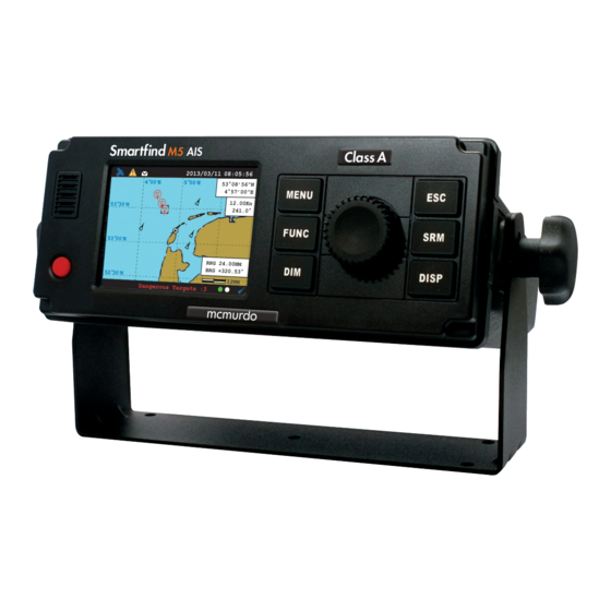
4 OPERATION 4.1 Panel Description Panel Description Figure 16 Item Number Name Descriptions Power Power On/Off (push button) Switch Beeper Sounds when buttons pushed and by MOB Alarm 3.5” LCD colour screen Display MENU Return to main menu / detail menu select Different function on display mode (Zoom In/Out, etc) FUNC and has different roles in submenus... -
Page 28: Status Bar
4.1.1 Status Bar The status bar constantly indicates Date (YYYY/MM/DD), Time, GPS status, ALR, and SRM. Status Bar 2013/01/01 07:18:11 MY SHIP: 1°13’02”N 103°48’32”E 12.00Kn 360.0° MY SHIP: Own Ship Own Ship 12.00Kn 0.0° 12.000NM Targets Received: 3 Status Bar Figure 17 GPS Status:Position fixed GPS Status:Non-fixed... -
Page 29: Transmission And Reception Bar
4.1.2 Transmission and Reception Bar The Transmission & Reception bar constantly displays real time status of transmissions and receptions on any display modes. The 3 default displayed messages are received AIS targets, dangerous targets, and Tx power level. 2013/01/01 07:18:11 MY SHIP: 1°13’02”N 103°48’32”E... -
Page 30: Display Modes
4.2 Display Modes For quick access, users can rotate display modes by simply pressing the DISP button. Display Mode Screen Shot Purpose Display all targets on basic coastline map Coastal View (Refer to section 4.2.2 Coastal View) MY SHIP RNG 39.54NM BRG +320.53°... -
Page 31: Target Symbol Descriptions
Shows the GPS satellite current usage GPS Satellite status Information (Refer to section 4.12 GPS Status) Show all the Region of own ship Region Setting List (Refer to section 4.7.3 Own Ship Detail) 4.2.1 Target Symbol Descriptions Symbols for each AIS target displayed on the radar view is as described below: Own Ship GPS Reception: Normal / Colour: Black and Grey Under normal GPS reception, own ship is located in the centre of the radar... - Page 32 Lost Signal Colour: Black / Red Cross If reception of an AIS target has ceased over 10 minutes, a “X” will be Target displayed over it. The target will disappear from the Radar View after its reception has ceased for one hour. AtoN (Real) Colour: Black / Plus Sign The icon will be displayed if any AIS AtoN (Aids to Navigation) Real is in...
-
Page 33: Coastal View
4.2.2 Coastal View 2013/01/17 07:18:11 4°00’E 5°00’E 53°08’56”N 4°57’00”E Own Ship 12.00Kn Selected 53°30’N information 241.0° Target 53°00’N MY SHIP Target RNG 39.54NM information BRG +320.53° 52°30’N 12 NM Function Targets Received :10 Icon Coastal View Figure 19 Item Function Own Ship Own-ship information for latitude, longitude, SOG and COG information... -
Page 34: Radar View
4.2.3 Radar View 2013/01/17 07:18:11 Own ship MY SHIP information Systems 1°13’02”N 103°48’32”E Current mode 12.00Kn 360.0° Target MY SHIP information Systems Own Ship Own Ship 12.00Kn Selected target Function icon 0.0° 12.00NM TX POWER LEVEL :12.5W Radar View Figure 20 Radar View displays own ship and target ships’... -
Page 35: Entering Text
4.3 Entering Text The knob on the front control panel is used for entering and editing text. The figures below show the text entering procedures. A. Turn the knob to traverse the menu items up or down. Once selected, press the knob to select the item for text entering. - Page 36 Select a character position Turn knob to move Press to start left or right editing Pick character Turn knob to select Press knob to character confirm character selection Confirm and save To save entered text, long press the knob for 2 seconds Entering Text Figure 21...
-
Page 37: Menu Tree Overview
4.4 Menu Tree Overview Press MENU button to enter MAIN MENU. Please note inland menus, Inland Messages and Inland Settings, are only available when the unit operates under inland mode. MESSAGES INBOX SRM (4.5.1) OUTBOX SRM (4.5.2) BROADCAST SRM (4.5.3) ADDRESSED SRM (4.5.4) LR INBOX (4.5.5) VESSEL DATA SET. -
Page 38: How To Access And Use Main Menu
4.4.1 How to access and use MAIN MENU 2013/01/17 07:18:11 MENU MAIN MENU MESSAGES NAV. STATUS SHIP SETTING TRANSCEIVER SYS CONFIG DIAGNOSTICS Dangerous Targets :0 Main Menu Figure 22 Rotate knob to select MAIN MENU items and push the knob to select sub-menu items. 2013/01/17 07:18:11 MENU MAIN MENU... -
Page 39: Menu Item Brief Description
4.4.2 Menu Item Brief Description MESSAGES INBOX SRM Log of safety related messages (SRM) received OUTBOX SRM Log of safety related messages (SRM) sent BROADCAST SRM Send SRM. ADDRESSED SRM Send specified targeted SRM. LR INBOX Log of received inquiry messages from others. INLAND MESSAGES ETA/RTA INBOX Log of ETA(RFM21), RTA(RFM22) message received... - Page 40 NUMBER OF PERSON Set number of persons BLUE SIGN SET. Set Blue sign settings REPORT RATE SET. Set report rate settings TRANSCEIVER (Settings for AIS receiving and sending) AIS TX Transceiver status: turn on or off AIS message transmitting DSC RX DSC Monitor: turn on or off DSC monitoring function GPS antenna feeding voltage: set to 3.3V or 5V GPS ANT.
-
Page 41: Messages
4.5 Messages The M5 features SRM alert pop-ups that can appear any time during operation. When a SRM (Safety Related Messages) from other AIS equipped vessels is received, you can either read and acknowledge it by pressing the knob or ignore the message by press ESC. If there is any unread message, the upper left corner will display , the new message icon. -
Page 42: Outbox Srm
4.5.2 Outbox SRM You can read all sent SRM messages under OUTBOX. Turn the knob to traverse the message list and highlight your choice. Read the message content by pressing the knob. 2013/01/17 22:44:22 2013/01/17 22:43:39 MESSAGE OUTBOX MESSAGE TEXT ----- MESSAGE ----- DATE/TIME -- TX --ACK MMSI 211111111 TX OK YES... -
Page 43: Addressed Srm
4.5.4 Addressed SRM ADDRESSED SRM means a SRM addressed to a certain MMSI number which can be selected from the target list or input manually. By entering into the submenu “ADDRESSED SRM”, users will be prompted to select the addressee from the target list. Here you can either pick the addressee or press ESC to leave the target list and enter the MMSI number manually. -
Page 44: Long Range Srm
4.5.5 Long Range SRM When the transponder is connected to a long range communication system via the long range communication port then long range interrogations may be received. These are requests for information from a distant base station beyond normal AIS operation range. LONG RANGE SRM holds all received Long Range Interrogation messages. -
Page 45: Eta/Rta Inbox
4.6.1 ETA/RTA Inbox The received messages of ETA (RFM21) and RTA (RFM22) can be read in the ETA/RTA Inbox. Turn the knob to traverse the message list and highlight your choice. Read the message content by pressing the knob. 2013/01/17 23:27:10 2013/01/17 23:27:10 ETA/RTA INBOX MESSAGE INFORMATION... -
Page 46: Pob Outbox
After the addressee is selected, you can configure the ETA message. 2013/01/17 23:27:10 2013/01/17 23:27:10 MMSI AIS TARGET LIST CREATE ETA REPORT [001]-NAME/MMSI------ET-BRG( °)-RNG(KM) DESTINATION MMSI [200000001] TX CHANNEL <ALTERNATE> 1. TEST01 15.09 RNG(KM)DATE/TIME---- 200000001 --------------- ETA INFORMATION --------------- UN Location [BTG] UN Country [UK] Fairway Number [ABCDE]... -
Page 47: Create Pob Message
4.6.5 Create POB Message In this submenu users can compose number of person on board (RFM55/IFM16) messages. Number of person on-board can be configured in Inland Setting 4.9.3. By entering into the submenu, users will be prompted to select the addressee from the target list. Here you can either pick the addressee from the list or press ESC to leave the target list to enter the MMSI number manually or broadcast the POB message without specifying any addressee. -
Page 48: Water Level
4.6.7 Water Level This submenu displays received water level (RFM24) messages from base station to ship about local water level information. 2013/01/17 23:27:10 2013/01/17 23:27:10 WATER LEVEL INFORMATION WATER LEVEL Sour. MMSI 200000001 READ YES ------- MMSI ---- TYPE --- DATE/TIME-- READ TIME 2013/07/03 18:16:51... -
Page 49: Own Ship
4.7.1 Own Ship This option displays the full information on your ship, including both dynamic and static data. Turn the knob to change between dynamic and static information. Static data and Dynamic Data 2013/01/17 22:43:39 2013/01/17 22:43:39 000/023 OWN SHIP <1/2> OWN SHIP <2/2>... -
Page 50: Ais Targets
4.7.2 AIS Targets This option displays all received AIS information of other vessels including dynamic and static information. Press the knob to select an AIS target and then press the knob to go through dynamic and static information of the selected vessel. There are two pages of ship details for SOLAS mode and another two pages for inland mode. - Page 51 Adding Friend Ship In the list, press FUNC button will open the pop-up window with the question whether the selected vessel should be added to your FRIEND SHIP list, or to sort the list according to vessels’ MMSI, distance, or direction. 2013/01/17 22:44:22 AIS TARGET LIST [013] - NAME/MMSI ---ET-- BRG(...
-
Page 52: Region List
4.7.3 Region List The region list displays all saved region areas. Turn the knob to traverse the list. Press the knob enables you to read the highlighted region information. 2013/01/17 23:26:20 2013/01/17 22:43:39 REGION SETTING LIST REGION [1] SETTING --- Region No---- Source ------- Date/Hour -- LAT(NE) 020°24’00”N Region 1... -
Page 53: Alarm List
4.7.4 Active Alert The M5 features SART/MOB alarm that can appear any time during operation. When SART/MOB message is received, the icon will appear in the status bar with beeping sounds from the beeper. Press any button to stop the sound. An example of an alarm message is shown below. Own Ship --------- ---------... - Page 54 BIIT ID Alert Alert text Additional information Prio Cat Escal Identifier (Alert instance) 3108 Locating device Check AIS targets 3062 General fault Check AIS equipment Not transmitting, check AIS 3008 Transceiver fail Not receiving, check AIS 3、4 Own ship position not 3015 Lost position transmitted...
- Page 55 4.7.5 Active BIIT List The M5 features SART/MOB alarm that can appear any time during operation. When SART/MOB message is received, the icon will appear in the status bar with beeping sounds from the beeper. Press any button to stop the sound. An example of an alarm message is shown below. Own Ship --------- ---------...
-
Page 56: Alarm History
4.7.6 BIIT History This submenu lists all recorded alarm and its time of occurrences. 2013/01/17 07:18:11 2013/01/17 22:44:22 MENU ALARM HISTORY MAIN MENU ---- ID -- Text ----------------------DATE-- TIME- NAV. STATUS 1. 35. No valid ROT 12/24 09:27 MESSAGES 2. 32. Heading lost 12/24 09:27 OWN SHIP NAV. -
Page 57: Dangerous List
2013/01/17 22:43:39 SENSOR STATUS POSITION STATUS EXT. GNSS Position with RAIM <= 10 m UTC STATUS LOST COG STATUS EXT. COG SOG STATUS EXT. SOG HEADING STATUS VALID ROT STATUS VALID --DATE TIME--CHANNEL PARAMETER CHANGE-- TX POWER LEVEL: 12.5W Sensor Status Figure 52 4.7.8 Dangerous List... -
Page 58: Mob List
4.7.9 MOB List With the setup of MOB list, MOB can be easily traced by the person’s name not just by the MMSI number on the MOB device. This submenu enables adding, removing, or modifying of MOB list entries. 2013/01/17 17:04:38 2013/01/17 17:04:39 MOB LIST MOB LIST... -
Page 59: Ship Setting
4.8 Ship Setting This menu list provides access to settings that are required during installation of the transponder. There are a total of 5 submenus. 2013/01/17 07:18:11 MENU MAIN MENU SHIP SETTING MESSAGES OWN SHIP NAV. STATUS VOYAGE SHIP SETTING CPA/TCPA TRANSCEIVER SET MMSI/IMO/ENI... -
Page 60: Voyage
4.8.2 Voyage 4.8.2.1 SOLAS Mode 20 1 3 /01/17 22:43:39 20 1 3 /01/17 22:43:39 VO YAGE SETTING VOYAGE SETTING DESTIN DESTIN [00/00 00:00] [00/00 00:00] CARGO <N/A or Harmless> CARGO <N/A or Harmless> Save data? NAV. <Under way using engine> NAV. -
Page 61: Cpa/Tcpa
4.8.3 CPA/TCPA In this submenu the closest point of approach (CPA) and time to CPA (TCPA) can be set. The vessels with insufficient CPA and TCPA will be displayed in the dangerous list (see 4.7.8) and on coastal and radar view. ... - Page 62 4.8.5 SET MMSI/IMO/ENI This section is password protected and can only be accessed using the password (see 4.11.6). 4.8.5.1 SOLAS Mode This submenu provides access to set MMSI and IMO. Use the knob to choose the menu option either MMSI or IMO. This function is for installation only 2013/01/17 22:43:39 SET MMSI/IMO/ENI...
-
Page 63: Retry Times
2013/01/17 22:43:39 2013/01/17 22:43:39 SET MMSI/IMO/ENI ENI SETTING [A1234567] MMSI [200000000] [000000000] Targets Received: 10 Dangerous Targets :0 ENI Setting Figure 64 When setting is done, press ESC to exit. 4.8.6 Retry Times In order to resend messages when the transmitted Message 6 or Message 12 receives no acknowledgement of Message 7 or Message 13, you can set how many times you want the system to resend messages. - Page 64 2013/01/17 22:43:39 MENU MAIN MENU INLAND SETTING MESSAGES VESSEL DATA SET. INLAND MESSAGES ETA SETTING NAV. STATUS NUMBER OF PERSON SHIP SETTING BLUE SIGN SET. INLAND SETTING REPORT RATE SET. TRANSCEIVER SYS CONFIG DIAGNOSTICS Dangerous Targets :0 Submenus under Inland Setting Figure 66...
-
Page 65: Vessel Data Setting
4.9.1 Vessel Data Setting Inland related vessel data can be set in this submenu: ERI Ship Type – ERI classification code. Blue Cones - The number of blue cones or blue flag status for the cargo (1, 2 or 3 blue cones, or blue flag). -
Page 66: Number Of Person
To save the settings, press MENU or ESC and the system will ask whether the changes should be saved. Select OK to save or CANCEL to discard and return to main menu. 4.9.3 Number of Person This submenu provides Number of Person (RFM55) setting: The number of crew (0 to 254 or unknown), passengers (0 to 8190 or unknown) and other shipboard personnel (0 to 254 or unknown). -
Page 67: Transceiver
4.10 Transceiver The submenu allows the users to switch on or off the transmission, change the supplied voltage of the GPS antenna between 3.3V and 5V, and allows the transmission power to be switched between 12.5W, as "normal", and 1W. 2013/01/17 22:43:39 TRANSCEIVER SETTING AIS TX... -
Page 68: Customize
4.11.1 Customize Customize provides personalization settings: Dimmer Level - brightness setting from 1 (low) to 100 (high) Colour mode - brightness and contrast adjustment for the LCD display along with selection of day or night operating mode. In night mode the display colours are inverted (light text on a dark background). -
Page 69: Map Calibration
RADAR VIEW ORIENTATION has NORTH UP/ COURSE UP / HEAD UP view modes. 4.11.3 Map Calibration This setting offers user functions to calibrate map data. Turn knob to select either latitude or longitude to offset. Press knob to enter input mode. Turn knob to select an offset value. Once finished press ESC to return to the previous level to continue the setting. -
Page 70: Factory
4.11.5 Factory This section is password protected and can only be accessed using the password (see 4.11.6). Press knob to confirm your choice and the following settings will be restored to their original value: MOB/Friend ship List, destination list, time zone, language, dimmer, CPA/TCPA and system password. -
Page 71: Long Range Setting
4.11.7 Long Range Setting This option provides user choices to auto-response remote interrogation and settings of the response information. You can either set MODE to either AUTO or MANUAL. The setting for the rest of information is either SUPPLY or REJECT. 2013/01/17 22:43:39 LONG RANGE INTERROGATION SETTING MODE... -
Page 72: Destination Table Setting
4.11.9 Destination Table Setting Save up to 10 destinations. Use rotary knob to traverse text and to modify. Press Menu to save changes. The Destination Table saves up to 10 frequently used destinations which can be conveniently configured in vessels voyage setting (see 4.8.2.1). 2013/01/17 22:43:39 DESTINATION TABLE SETTING Column 1... -
Page 73: Vswr Setting
4.11.11 VSWR Setting The VSWR setting function allows the fine-adjustment of the VSWR threshold, to allow for the cable length and VHF antenna characteristics. This function is password protected (see 4.11.6) and should be performed by a qualified service partner or dealer. 2013/01/17 07:18:11 2013/01/17 22:43:39 MENU... -
Page 74: Diagnostics
4.12 Diagnostics This submenu provides users to check system statuses. There are a total of 8 check options. 2013/01/17 07:18:11 MENU MAIN MENU DIAGNOSTICS MESSAGES SYSTEM ON/OFF NAV. STATUS MEMORY TEST SHIP SETTING SENSOR PORT TRANSCEIVER TFT-PANEL SYS CONFIG KEYBOARD TEST DIAGNOSTICS GPS STATUS Dangerous Targets :0... - Page 75 2013/01/17 22:43:39 Strength of GPS GPS Satellite Satellite Signal location Signal Own Ship Information 53°08’56”N 4°57’00”E Signal 12.00Kn 241.0° Dangerous Targets: 2 GPS Status Figure 86 Transceiver: this option provides user to view the frequencies and status. When finished, press ESC to exit.
- Page 76 Figure 90 Version Provide model name, hardware information, delivered firmware version on the unit, etc. When finished, press ESC to exit. 2013/01/17 22:43:39 VERSION PRODUCT Smartfind M5 AIS Class A FIRMWARE V1.0.6.47 COMPANY MY SHIP Systems B.V WEBSITE www.seasofsolutions.com 21-105-000001...
-
Page 77: Technical Specifications
5 TECHNICAL SPECIFICATIONS 5.1 Applicable Standards IEC 61993-2 Ed.3.0, 2018 IMO Resolution A.694(17) IEC 61108-1 Ed.2.0, 2003 IMO Resolution MSC.74(69) Annex 3 IEC 60945 Ed.4.0, 2002 incl. Corr. 1, 2008 IMO Resolution MSC.191(79) IEC 61162-1 Ed.5.0, 2016 ITU-R M.1371-5 (Class A), 2014 IEC 61162-2 Ed.1.0, 1998 ITU-R M.825-3, 1998 IEC 62288 Ed.2.0, 2014... -
Page 78: Gps Receiver (Internal)
5.4 GPS Receiver (Internal) Receiving Channels 50 channels Tracking & Navigation ≧ -159 dBm Sensitivity ≧ -159 dBm Reacquisition Sensitivity < 2.5 m Autonomous Horizontal Position < 2.0 m SBAS Receiver Type SBAS: WAAS, EGNOS, MSAS, GAGAN 5.5 Power Supply Supply Voltage 12V / 24V DC Less than 9W average @ 12V DC;... -
Page 79: Environmental
Alarm relay Normally closed Mini type B USB interface NMEA2000 IEC61162-3 Alarm Output Relay contact 5.9 Environmental IEC 60945 “protected” category Operating Conditions Operating Temperature -15°C ~ 55°C Operating Humidity 95% RH at 40°C Waterproof IPX2 5.10 Physical Width 261 mm (10.28 inch) Height 184 mm (7.25 inch) Depth (include connectors) -
Page 80: Nmea 2000 Pgn Information
5.12 NMEA 2000 PGN Information The following table is a list of the NMEA 2000 messages supported by the Smartfind M5 unit. The “Transmit” PGNs information includes “Own ship” + “Received AIS information from other ships”. This is the reason the NMEA2000 PGN list covers both Class A and Class B related information. -
Page 81: Mechanical Dimensions
6 MECHANICAL DIMENSIONS 6.1 Smartfind M5 Transponder Main Unit Front (size: mm) Side (size: mm) - Page 82 Back (size: mm) Bottom (size: mm)
-
Page 83: Junction Box
6.2 Junction Box 165 mm 6.3 Extension Cable 6.4 Mounting Template (not to scale) -
Page 84: Gps Antenna
6.5 GPS Antenna 6.6 Pilot Plug... -
Page 85: Troubleshooting
7 TROUBLESHOOTING Use the following guide to perform simple troubleshooting in case the transponder is not function accordingly. Symptom Possible Cause Solution Faulty connector to power Check power connection Transponder cannot power Polarity reverse Check power connection Power supply current too Check power supply Unit not powered up Press power key... -
Page 86: Abbreviations
8 ABBREVIATIONS Terms of abbreviations: Acknowledgement AtoN Aid to Navigation Automatic Identification System AUTO Automatic Alarm Auxiliary Antenna BIIT Built-In Integrity Test Bearing Channel Closest Point of Approach Course Over Ground DEST/DESTN Destination DISP Display DISP Display DIST Distance DGNSS Differential GNSS Digital Selective Calling DGPS... - Page 87 Multi-functional Satellite Minimum Keyboard and Display MSAS Augmentation System National Marine Electronics Navigation NMEA Association Nautical Mile Output Presentation Interface Receiver Autonomous Integrity RAIM Rate of Turn Monitoring Radio Technical Commission Relative Humidity RTCM for Maritime services Range Receive / Receiver Second Speed Over Ground SART...
-
Page 88: Warranty Statement
9 WARRANTY STATEMENT IMPORTANT WARRANTY INFORMATION/REGISTRATION McMurdo AIS products carry a standard 12 month warranty from date of purchase. McMurdo also offers additional warranty but requires that your product be registered within 90 days of purchase. For further information and to register your product warranty on line please visit:... -
Page 89: Iec 61162-2 Data Interface
APPENDIX (A) IEC 61162-2 Data Interface The Smartfind M5 Class A AIS Transponder provides 2 types of IEC 61162-2 data interfaces for user applications. The first interface type includes 3 input-only sensor data ports and the second interface type includes 4 bidirectional input/output ports. Data port for each interface type will be described in the following section below. - Page 90 A.1.2 Bidirectional Data Ports The schematic of bidirectional data port is shown in Figure A2. The schematics includes an isolated full duplex RS-485 transceiver IC (Texas Instrument ISO3080) which is used as the main component to handle both data input and output from external data source. The transceiver IC is isolated from external input.
-
Page 91: Presentation Interface Of Smartfind M5
Presentation Interface of Smartfind M5 Sensor Inputs PI Port No. 61162-1 Minimum required input sentences: Position GNS, GLL, RMC, GGA int/ext * 61162-2 int/ext * RMC,VBW, VTG int/ext * RMC, VBW, VTG 61162-1 Heading HDT, HDG, THS, OSD, VHW 61162-2... -
Page 92: Supported Iec 61162 Data Sentences
Supported IEC 61162 Data Sentences Data Port Input Sentences Output Sentences Sensor 1 DTM, GNS, RMC, VBW, HDT, HDG, Sensor 2 ROT, GBS, GLL, VTG, THS, GSA, Sensor 3 GGA, OSD, VHW DTM, GNS, RMC, VBW, HDT, HDG, DGPS ROT, GBS, GLL, VTG, THS, GSA, GGA, OSD, VHW ABK, ACA, VDM, VDO, ABM, ACA, ACK, AIR, BBM, SSD,... -
Page 93: Interpretation Of Input Sentences
Interpretation of Input Sentences A.5.1 ABM – AIS Addressed Binary and Safety Related Message This sentence supports ITU-R M.1371 Messages 6, 12, 25, 26 and provides an external application with a means to exchange data via an AIS transponder. !--ABM,x,x,x,xxxxxxxxx,x,xx,s—s,x*hh<CR><LF> Field No. - Page 94 A.5.3 ACK – Acknowledge Alarm This sentence is used to acknowledge an alarm condition reported by a device. $--ACK,xxx*hh<CR><LF> Field No. Format Description Remark Unique alarm number (identifier) at alarm source A.5.4 AIQ - Query Sentence This sentence is used to inquire AIS sentence information. $--AIQ,c—c*hh<CR><LF>...
- Page 95 A.5.6 BBM – AIS Broadcast Binary Message This sentence supports generation of ITU-R M.1371 binary messages 8, 14, 25, and 26. This provides the application with a means to broadcast data, as defined by the application only. !--BBM,x,x,x,x,x.x,s—s,x*hh<CR><LF> Field No. Format Description Remark...
- Page 96 A.5.9 GBS – GNSS Satellite Fault Detection This sentence is used to support receiver autonomous integrity monitoring (RAIM). $--GBS, hhmmss.ss, x.x, x.x, x.x, xx, x.x, x.x, x.x *hh <CR><LF> Field No. Format Description Remark hhmmss.s UTC time of the GGA or GNS fix associated with this sentence Expected error in latitude Expected error in longitude...
- Page 97 A.5.12 GNS – GNSS Fix Data Fix data for single or combined satellite navigation systems (GNSS). This sentence provides fix data for GPS, GLONASS, possible future satellite systems and systems combining these. $-- GNS, hhmmss.ss, llll.ll, a, yyyyy.yy, a, c--c,xx,x.x,x.x,x.x,x.x,x.x,a *hh<CR><LF>...
- Page 98 A.5.14 HDG – Heading, Deviation and Variation Heading (magnetic sensor reading), which if corrected for deviation will produce magnetic heading, which if offset by variation will provide true heading. $--HDG, x.x, x.x, a, x.x, a*hh<CR><LF> Field No. Format Description Remark Magnetic sensor heading, degrees x.x,a Magnetic deviation, degrees E/W...
- Page 99 A.5.18 OSD – Own Ship Data Heading, course, speed, set and drift summary. Useful for, but not limited to radar/ARPA applications. OSD gives the movement vector of the ship based on the sensors and parameters in use. $--OSD, x.x,A,x.x, a,x.x,a,x.x,x.x,a*hh<CR><LF> Field No.
- Page 100 A.5.21 SPW - Security Password Sentence This sentence can be used for authentication. For this purpose the sentence has to be applied before the protected sentence (for example EPV, SSD). $--SPW,ccc,c--c,x,c--c*hh<CR><LF> Field No. Format Description Remark Password protected sentence c--c Unique Identifier Password level c--c...
- Page 101 Status , ground speed, A = data valid, V = data invalid Stern transverse water speed , knots ignored Status : stern water speed,A = data valid, V = ignored data invalid Stern transverse ground speed ,knots ignored Status : stern ground speed,A = data valid, V = ignored data invalid A.5.25 VHW –...
- Page 102 A.5.28 PAMC, DBG – Proprietary Sentences, Debug The proprietary sentences are additional sentences only applicable to this product. Its main usage is for enabling testing mode and parameter settings. This sentence is used for configuration. It commands unit with given parameters. $PAMC,C,c-c,x,x,x,x,x,x,x,x*hh<CR><LF>...
- Page 103 Interpretation of Output Sentences A.6.1 ABK – AIS Addressed and Binary Broadcast Acknowledgement The ABK-sentence is generated when a transaction, initiated by reception of an ABM, AIR, or BBM sentence, is completed or terminated. $--ABK,xxxxxxxxx,x,x.x,x,x*hh<CR><LF> Field No. Format Description Remark xxxxxxxx MMSI of the addressed AIS unit AIS channel of reception...
- Page 104 A.6.3 ALR – Set Alarm State Local alarm condition and status. This sentence is used to report an alarm condition on a device and its current state of acknowledgement. $--ALR,hhmmss.ss,xxx,A, A,c--c*hh<CR><LF> Field No. Format Description Remark hhmmss.ss Time of alarm condition change, UTC Unique alarm number (identifier) at alarm source Alarm condition,...
- Page 105 A.6.6 LR2 – AIS Long-Range Reply Sentence 2 The LR2-sentence contains the information items requested by the “B, C, E and F” functionidentification characters,(see the LRF sentence) LR2,x,xxxxxxxxx,xxxxxxxx,hhmmss.ss,llll.ll,a,yyyyy.yy,a,x.x,T,x.x,N*hh<CR> <LF> Field No. Format Description Remark Sequence number xxxxxxxxx MMSI of responder xxxxxxxx Date: ddmmyyyy, 8 digits hhmmss.ss...
- Page 106 A.6.9 TXT – Text Transmission For the transmission of short text messages. Longer text messages may be transmitted by using multiple sentences. $--TXT,xx,xx,xx,c--c*hh<CR><LF> Field No. Format Description Remark Total number of sentences Sentence number Text identifier c--c Text message A.6.10 VDM – AIS VHF Data-Link Message This sentence is used to transfer the entire contents of a received AIS message packet, as defined in ITU-R M.1371 and as received on the VHF Data Link (VDL), using the “six-bit”...
-
Page 107: Interpretation Of Output Sentences
001 at the related PI port. Detection of Rx Malfunction The Smartfind M5 also has 3 built-in lock detectors (high active) to monitor each local oscillator (PLL circuit) of receiver channel 1, channel 2, and channel 70 respectively. If the operation of PLL circuit becomes abnormal, a logic low level will be sent from the lock detector to notify the system. -
Page 108: Installation And Maintenance Record
APPENDIX (C) Installation and Maintenance Record The following installation record should be completed and retained on board the vessel for maintenance records. Vessel Information Vessel Name Flag State IMO Number MMSI Number Owner/Company Radio call sign Type of vessel Gross tonnage Length m Beam AIS Class A Transponder Information... - Page 109 Connected Sensors and Devices Connected Port Equipment Model Number Sensor 1 Sensor 2 Sensor 3 Ext Display Port Pilot Port Long Range Port DGNSS Data Port Other Device Installer Information Company Name Technician’s Name Telephone/Mobile No. Address Place Date Installer’s Signature...
-
Page 110: Software Revisions
Software Revisions The transponder is delivered with software version according to the following table which is to be filled in and maintained either by manufacturer, distributor, dealer, or Installation Company. When software update is done, the new software (firmware) version can be identified through MKD at MENU/DIAGNOSTICS/VERSION (please refer to section 4.12 in the manual). -
Page 111: Uscg Ais Inspection Checklist & Report
APPENDIX (D) USCG AIS Inspection Checklist & Report For USA vessel owners, please visit the USCG website to download the voluntary checklist to assist the surveyor or owner in ensuring the ship’s Automatic Identification System (AIS) in operation is properly operating as defined in 33 CFR §164, 47 CFR §80, and, Safety of Life at Sea Convention (SOLAS) Chapter V Regulation 18.9. - Page 112 Note:...
- Page 113 21-135-001N Issue 15...
Need help?
Do you have a question about the Smartfind M5 and is the answer not in the manual?
Questions and answers