Table of Contents
Advertisement
SHERWOOD INDUSTRIES IS AN ENVIRONMENTALLY RESPONSIBLE COMPANY. THIS MANUAL IS PRINTED ON RECYCLED PAPER.
PLEASE KEEP THESE INSTRUCTIONS FOR FUTURE REFERENCE.
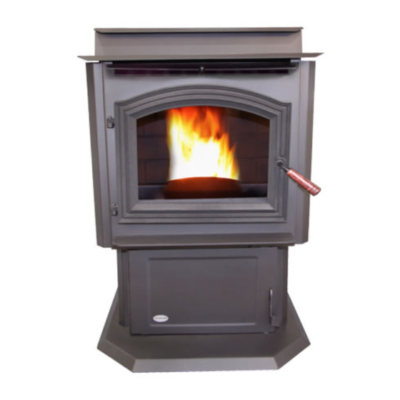
PELLET STOVE
VF-55-FS
TECHNICAL MANUAL
PLEASE READ THIS ENTIRE MANUAL BEFORE INSTALLATION
AND USE OF THIS PELLET-BURNING ROOM HEATER. FAILURE
TO FOLLOW THESE INSTRUCTIONS COULD RESULT IN
PROPERTY DAMAGE, BODILY INJURY OR EVEN DEATH.
Contact your building or fire officials about restrictions and installation
inspection requirements in your area.
50-2087
Advertisement
Table of Contents

Related Manuals for Vistaflame VF-55-FS


Summary of Contents for Vistaflame VF-55-FS
- Page 1 SHERWOOD INDUSTRIES IS AN ENVIRONMENTALLY RESPONSIBLE COMPANY. THIS MANUAL IS PRINTED ON RECYCLED PAPER. PLEASE KEEP THESE INSTRUCTIONS FOR FUTURE REFERENCE. PELLET STOVE VF-55-FS TECHNICAL MANUAL PLEASE READ THIS ENTIRE MANUAL BEFORE INSTALLATION AND USE OF THIS PELLET-BURNING ROOM HEATER. FAILURE TO FOLLOW THESE INSTRUCTIONS COULD RESULT IN PROPERTY DAMAGE, BODILY INJURY OR EVEN DEATH.
-
Page 2: Table Of Contents
Table of Contents Safety Warnings & Recommendations....................3 Specifications..........................5 Rating Label & Location......................5 Dimensions..........................6 Specifications...........................6 Installation.............................7 Deciding Where to Locate your Pellet Appliance................7 Removing Pellet Stove From Pallet.....................7 Clearances to Combustibles.......................8 Pedestal Base Adjustment......................8 Thermostat Installation......................8 Vent Termination Requirements....................9 Outside Fresh-Air Connection....................10 Exhaust And Fresh Air Intake Locations..................10 Mobile Home Installation......................11 Corner Through Wall Installation....................11... -
Page 3: Safety Warnings & Recommendations
Safety Warnings & Recommendations * This manual is designed for the technician in conjunction with the owner’s manual. * Please read this entire Technical Manual before installing or operating your Vista Flame Pellet Stove. Failure to follow these instructions may result in property damage, bodily injury or even death. - Page 4 Safety Warnings & Recommendations ELECTRICAL: The use of a surge protected power bar is recommended. The unit must be grounded. The grounded electrical cord should be connected to a standard 110-120 volts (4.2 Amps), 60 hertz electrical outlet and also must be accessible. If this power cord should become damaged, a replacement power cord must be purchased from the manufacturer or a qualified Vista Flame dealer.
-
Page 5: Specifications
Specifications & l ating abel ocation The rating label is located on the inside of the hopper lid. -
Page 6: Dimensions
(756mm) " (601mm) " (656mm) " (928mm) " (301mm) Figure 2: Dimensions of VF-55-FS. pecificationS Input rating when using: Wood Pellets/Corn - 55,000BTU (16.1KW•hr) & Wheat/Barley - 53,000BTU (15.5KW•hr). Table 1: VF-55-FS Specifications. Description Fuel type Residential Pellet Heater 6mm (¼”) dia. Pellets - wood, corn, wheat, & barley*... -
Page 7: Installation
Installation eciding here to ocate your ellet ppliance 1. Do not install the stove in a bedroom or room where people sleep in. 2. Locate the stove in a large and open room that is centrally located in the house. This will optimize heat circulation. -
Page 8: Clearances To Combustibles
Alcove Minimum Height 60 inches (152 cm) The unit must be installed with a minimum of 6” (152 mm) of floor protection in front of and to the sides of Figure 4: VF-55-FS Clearance to Combustibles. the door opening. edeStal... -
Page 9: Vent Termination Requirements
Installation ermination equirementS IT IS RECOMMENDED THAT YOUR PELLET STOVE BE INSTALLED BY AN AUTHORIZED DEALER/INSTALLER. Table 2: Use in conjunction with Figure 7 for allowable exterior vent termination locations. Letter Minimum Clearance Description 24 in (61 cm) Above grass, top of plants, wood, or any other combustible materials. 48 in (122 cm) Beside/below any door or window that may be opened. -
Page 10: Outside Fresh-Air Connection
(161 mm) FRESH AIR INTAKE. " Base of unit to center of intake 5" " (465mm) (128mm) ” (378 mm) (161mm) Center of unit to center of intake " 5” (128 mm) (378mm) Figure 9: VF-55-FS Inlet and Outlet Location. -
Page 11: Mobile Home Installation
Installation obile nStallation ● Secure the heater to the floor using the four (4) holes in the pedestal. ● Ensure unit electrically grounded to the chassis of your home (permanently). ● Do not install in a room people sleep in. ●... -
Page 12: Horizontal Exhaust Through Wall Installation
Installation orizontal xhauSt hrough nStallation Vent installation: install vent at clearances specified by the vent manufacturer. A chimney connector shall not pass through an attic or roof space, closet or similar concealed spaces, or a floor, or ceiling. Where passage through a wall or partition of combustible construction is desired, the installation must conform to CAN/CSA-B365 Installation Code for Solid-Fuel-Burning Appliances and Equipment and with all local regulations, including those referring to regional and national. - Page 13 Installation 8. The pipe must extend at least 12” (30 cm) away from the building. If necessary, bring another length of pipe to the outside of the home to connect to the first section. Do not forget to place high temperature silicone around the pipe that passes through the thimble if required by vent manufacturer.
-
Page 14: Recommended - Through Wall With Vertical Rise And Horizontal Termination Installation
Installation recommended - t hrough ertical iSe and orizontal ermination nStallation Termination cap 90°elbow Wall framing A 45° down elbow with a screen may be used in Vertical section place of the termination cap (or stainless steel of vent pipe termination hood). -
Page 15: Outside Vertical Installations
Installation utSide ertical nStallationS To accomplish an outside vertical pipe installation, follow the “h ” OrizOntAl xhAust hrOugh nstAllAtiOns section and then finish it by performing the following (refer to Figure 16). 1. Install a tee with clean out on the outside of the house. 2. -
Page 16: Inside Vertical Installations
Installation nSide ertical nStallationS 1. Place the unit on the hearth pad if a hearth pad is to be used (or on solid material if installed on a carpeted surface) and space the unit in a manner so when the pellet vent is installed vertically, it will meet the minimum clearance from a combustible wall stated by the vent manufacturer. -
Page 17: Hearth Mount Installation
Installation earth ount nStallation Damper Removed or Fastened Open Mantel Minimum (8") 200mm from top of stove Clean-out tee Min (6") 150mm Fresh-air intake should com from chimney. If holes already exist fresh-air intake Floor can be taken through back Protection of the fireplace or through the ash dump. -
Page 18: Slider/Damper Set-Up
Installation lider amper This is used to regulate the airflow through the pellet stove. The slider damper should only be adjusted if the desired flame setting could not be achieved using the Circuit Boards Air Trim Button. Convection Slider Damper Slider Damper Set Screw with "... -
Page 19: Troubleshooting
Troubleshooting DO NOT: ● Service the stove with wet hands. The stove is an electrical appliance, which may pose a shock hazard if handled improperly. Only qualified technicians should deal with possible internal electrical failures. ● Do not remove from the firebox any screws without penetrating oil lubrication. WHAT TO DO IF: 1. - Page 20 Troubleshooting • Exhaust Temperature Sensor failure. Bypass sensor located on Exhaust Blower, if stove now operates properly, the unit may require cleaning or a new sensor. Contact your local dealer for service. • Check the agitator to make sure it is turning properly 3.
- Page 21 Troubleshooting 8. Ignitor - the pellets will not light. • Check the line fuse to see if it has blown. NOTE: The ignitor should be bright orange in color. • Everything else in the stove operates but the ignitor will not light the pellets. •...
-
Page 22: Wiring Diagram
Wiring Diagram Black Brown 2µF Capacitor Black Exhaust Blue Combustion Temperature Brown Blower Blue Blue Sensor Black White 120V Ground Air Pump White Plug Green Ground Ignitor White Thermostat Ground 5 Amp White Agitator Blue/Yellow Black Motor White Auger Yellow Yellow Motor Purple... -
Page 23: Parts List
EC-001 ⅝” I.D. Auger Brass Bushings (Set Of 2) 50-1806 Stainless Steel Cast Agitator With Coupler 50-1697 Convection Blower 80mm 50-2064 Vistaflame Oval Decal 50-1900 Auger With Paddles 50-1161 Ignitor Coil Type -400 Watt 50-1691 Auger Stops (Clear Rubber) 50-1559... - Page 24 Parts List Reference # Description Part # Drive Chain 50-2059 ¼” Spring Pin 50-1701 Agitator Bushing Left Side 50-1703 Lower Ash Pan Door Complete 50-2071 Glass Only 14.88” X 11.36” 50-2056 Glass Retainer 50-2065 Burn Pot Scraper Tool 50-1254 Door And Ash Door Gasket Firm -10’...
-
Page 25: Parts Diagram - Components
Parts Diagram - Components... -
Page 26: Parts Diagram - Steel
Parts Diagram - Steel... -
Page 27: Warranty
Warranty Sherwood Industries Ltd. is the manufacturer of the Vista Flame line of heating products. At Sherwood Industries, our commitment to the highest level of quality and customer service is the most important thing we do. Each Vista Flame stove is built on a tradition of using only the finest materials and is backed by our Exclusive Lifetime Limited Warranty to the original purchaser. - Page 28 Warranty Exclusions and Limitations: 1. This Warranty does not cover tarnish, discoloration or wear on the plating or paint. 2. This Warranty excludes wear and tear or breakage caused by cleaning, moving or service on log set. 3. A qualified installer must install this stove or fireplace. This Limited Warranty covers defects in materials and workmanship only if the product has been installed in accordance with local building and fire codes;...
- Page 29 Warranty 17. Damage to plated surfaces caused by fingerprints, scratches, melted items, or other external scores and residues left on the plated surfaces from the use of abrasive cleaners or polishes is not covered in this warranty. 18. The Limited Warranty does not cover tarnish, discoloration or wear on the plated surfaces. 19.
-
Page 30: Installation Data Sheet
Installation Data Sheet The following information must be recorded by the installer for warranty purposes and future reference. NAME OF OWNER: NAME OF DEALER: _________________________________________ _________________________________________ ADDRESS: ADDRESS: _________________________________________ _________________________________________ _________________________________________ _________________________________________ _________________________________________ _________________________________________ PHONE:___________________________________ PHONE:___________________________________ MODEL:___________________________________ NAME OF INSTALLER: SERIAL NUMBER:___________________________ _________________________________________ DATE OF PURCHASE: _____________...
Need help?
Do you have a question about the VF-55-FS and is the answer not in the manual?
Questions and answers