Table of Contents
Advertisement
SHERWOOD INDUSTRIES IS AN ENVIRONMENTALLY RESPONSIBLE COMPANY. THIS MANUAL IS PRINTED ON RECYCLED PAPER.
PLEASE KEEP THESE INSTRUCTIONS FOR FUTURE REFERENCE.
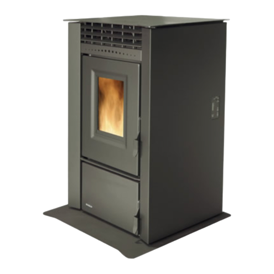
VF 170
PELLET STOVE
H E A R T H P R O D U C T S
TECHNICAL MANUAL
PLEASE READ THIS ENTIRE MANUAL BEFORE INSTALLATION
AND USE OF THIS PELLET-BURNING ROOM HEATER. FAILURE
TO FOLLOW THESE INSTRUCTIONS COULD RESULT IN
PROPERTY DAMAGE, BODILY INJURY OR EVEN DEATH.
Contact your building or fire officials about restrictions and installation
inspection requirements in your area.
50-1864
Advertisement
Table of Contents

Related Manuals for Vistaflame VF 170


Summary of Contents for Vistaflame VF 170
- Page 1 SHERWOOD INDUSTRIES IS AN ENVIRONMENTALLY RESPONSIBLE COMPANY. THIS MANUAL IS PRINTED ON RECYCLED PAPER. PLEASE KEEP THESE INSTRUCTIONS FOR FUTURE REFERENCE. VF 170 PELLET STOVE H E A R T H P R O D U C T S TECHNICAL MANUAL PLEASE READ THIS ENTIRE MANUAL BEFORE INSTALLATION AND USE OF THIS PELLET-BURNING ROOM HEATER.
-
Page 2: Table Of Contents
Table of Contents Safety Warnings & Recommendations....................3 Installation.............................5 Rating Label Location........................5 Deciding Where to Locate your Pellet Appliance................5 Removing Pellet Stove From Pallet.....................5 Dimensions & Specifications......................6 Clearances to Combustibles.......................7 Hearth Shield Installation......................7 Thermostat Installation......................7 Vent Termination Requirements....................8 Outside Fresh-Air Connection.....................9 Exhaust And Fresh Air Intake Locations..................9 Mobile Home Installation......................10 Corner Through Wall Installation....................10... -
Page 3: Safety Warnings & Recommendations
Safety Warnings & Recommendations * This manual is designed for the technician in conjunction with the owner’s manual. * Please read this entire Technical Manual before installing or operating your Vista Flame Pellet Stove. Failure to follow these instructions may result in property damage, bodily injury or even death. - Page 4 Safety Warnings & Recommendations ELECTRICAL: The use of a surge protected power bar is recommended. The unit must be grounded. The grounded electrical cord should be connected to a standard 110-120 volts (3.6 Amps), 60 hertz electrical outlet and also must be accessible. Ensure the polarity to the outlet, the unit will be plugged into, is correct as incorrect polarity can affect the unit’s operation.
-
Page 5: Installation
Installation ATING ABEL OCATION The rating label is located on the inside of the hopper lid. ECIDING HERE TO OCATE YOUR ELLET PPLIANCE 1. Do not install the stove in a bedroom or room where people sleep in. 2. Locate the stove in a large and open room that is centrally located in the house. This will optimize heat circulation. -
Page 6: Dimensions & Specifications
Installation & S IMENSIONS PECIFICATIONS " (553mm) " (403mm) " (716mm) " (568mm) 25" (637mm) " (680mm) " (605mm) " (671mm) " (1063mm) " (1048mm) 27" (687mm) Figure 2: Dimensions of VF170. Table 1: VF170 Specifications. Testing Standard Frequency Voltage ASTM 1509-04 60 Hz 110 - 120 V... -
Page 7: Clearances To Combustibles
Installation LEARANCES TO OMBUSTIBLES Back Wall 4" 4" (10cm) These dimensions are minimum clearances but it is (10cm) recommended that you ensure sufficient room for servicing, routine cleaning and maintenance. 12" (30.5cm) Side wall to unit 12 inches (30.5 cm) Back wall to unit 4 inches (10 cm) -
Page 8: Vent Termination Requirements
Installation ERMINATION EQUIREMENTS IT IS RECOMMENDED THAT YOUR PELLET STOVE BE INSTALLED BY AN AUTHORIZED DEALER/INSTALLER. Table 2: Use in conjunction with Figure 6 for allowable exterior vent termination locations. Letter Minimum Clearance Description 24 in (61 cm) Above grass, top of plants, wood, or any other combustible materials. 48 in (122 cm) Beside/below any door or window that may be opened. -
Page 9: Outside Fresh-Air Connection
Installation UTSIDE RESH ONNECTION This Heater must have adequate air for proper combustion in the room that it is installed. A Fresh-air intake is strongly recommended for all installations. Failure to install intake air may result in improper combustion as well as the unit smoking during �������... -
Page 10: Mobile Home Installation
Installation OBILE NSTALLATION ● Secure the heater to the floor using the four (4) holes in the pedestal. ● Ensure the unit is electrically grounded to the chassis of your home (permanently). ● Do not install in a room people sleep in. ●... -
Page 11: Horizontal Exhaust Through Wall Installation
Installation ORIZONTAL XHAUST HROUGH NSTALLATION Vent installation: install vent at clearances specified by the vent manufacturer. A chimney connector shall not pass through an attic or roof space, closet or similar concealed spaces, or a floor, or ceiling. Where passage through a wall or partition of combustible construction is desired, the installation must conform to CAN/CSA-B365 Installation Code for Solid-Fuel-Burning Appliances and Equipment and with all local regulations, including those referring to regional and national. - Page 12 Installation 8. The pipe must extend at least 12” (30 cm) away from the building. If necessary, bring another length of pipe to the outside of the home to connect to the first section. Do not forget to place high temperature silicone around the pipe that passes through the thimble.
-
Page 13: Recommended - Through Wall With Vertical Rise And Horizontal Termination Installation
Installation RECOMMENDED - T HROUGH ERTICAL ISE AND ORIZONTAL ERMINATION NSTALLATION Termination cap 90°elbow Wall framing A 45° down elbow may be used in place of the Vertical section termination cap (or stainless steel termination of vent pipe hood). Wall strap Horizontal frame for thimble... -
Page 14: Outside Vertical Installations
Installation UTSIDE ERTICAL NSTALLATIONS To accomplish an outside vertical pipe installation, follow the “H ” ORIZONTAL XHAUST HROUGH NSTALLATIONS section and then finish it by performing the following (refer to Figure 15). 1. Install a tee with clean out on the outside of the house. 2. -
Page 15: Inside Vertical Installations
Installation NSIDE ERTICAL NSTALLATIONS 1. Place the unit on the hearth pad if a hearth pad is to be used (or on solid material if installed on a carpeted surface) and space the unit in a manner so when the pellet vent is installed vertically, it will be 3”... -
Page 16: Hearth Mount Installation
Installation EARTH OUNT NSTALLATION Damper Removed or Fastened Open Mantel Minimum 200mm (8") from top of stove Clean-out Min 150mm (6") Fresh-air intake should com from chimney. If holes Floor already exist fresh-air Protection intake can be taken through back of the fireplace or Masonry Fireplace Combustible Floor through the ash dump. -
Page 17: Slider/Damper Set-Up
Installation LIDER AMPER This is used to regulate the airflow through the pellet stove. The slider damper should be set by a trained technician using magnehelic. 1. To install the optional slider damper Exhaust Channel rod remove the left cabinet side panel. Partially back out the two (2) T-20 Torx screws on the back of the each panel and Exhaust Fan... -
Page 18: Troubleshooting
Troubleshooting DO NOT: ● Service the stove with wet hands. The stove is an electrical appliance, which may pose a shock hazard if handled improperly. Only qualified technicians should deal with possible internal electrical failures. ● Do not remove from the firebox any screws without penetrating oil lubrication. WHAT TO DO IF: 1. - Page 19 Troubleshooting üPoor Quality Fuel – Insufficient energy in the fuel to produce enough heat to keep the stove burning üExhaust Temperature Sensor failure. – Bypass sensor located on Exhaust Blower, if stove now operates properly, the unit may require cleaning or a new sensor. Contact your local dealer for service. üCheck the fuse on the circuit board.
- Page 20 Troubleshooting 7. The convection blower will not function normally. üClean all grill openings at the back and below unit . üCheck the Voltage across the blower wires, It should adjust with the heat output settings. If not contact your local dealer for service. 8.
-
Page 21: Wiring Diagram
Wiring Diagram Brown Exhaust Temperature Sensor Brown White Combustion Blue Blower Black White 120V Black Grounded Plug Ignitor Ground Thermostat White Auger Motor Black White Yellow 5 Amp Fuse Vacuum Yellow Switch Black Yellow White Blue Brown Brown White Convection Purple Purple Blower... -
Page 22: Parts List
Parts List Reference # Description Part # 120ºF (49ºC) Ceramic Fan Temp Sensor EC-001 IEC Power Cord (115V) EC-043 Window Channel Tape - 6ft (1.8m) EC-058 High Limit Temp Sensor 200ºF (93ºC) Manual Reset EF-016 Silicone Hose EF-018 Slider Damper Rod with Knob EF-050 Glass - Large (9”... - Page 23 Parts List Reference # Description Part # Slider Damper Plate 50-1644 Firebox Baffle 50-1645 Ash Pan 50-1646 Glass Retainer 50-1649 Inner Door (No Glass) 50-1651 Control Panel with Decal 50-1654 Circuit Board 50-1655 Ignitor Assembly 50-1656 Auger Motor - 3rpm 120V 50-1657 Auger Plate And Bushing (Assembly) 50-1658...
-
Page 24: Parts Diagram - Components
Parts Diagram - Components VF 170 - Components May 2008 � �� �� � �� �� �� �� �� �� � �� �� �� �� � �� �... -
Page 25: Parts Diagram - Steel
Parts Diagram - Steel... -
Page 26: Warranty
Warranty Sherwood Industries Ltd. is the manufacturer of the Vista Flame line of heating products. At Sherwood Industries, our commitment to the highest level of quality and customer service is the most important thing we do. Each Vista Flame stove is built on a tradition of using only the finest materials and is backed by our Exclusive Lifetime Limited Warranty to the original purchaser. - Page 27 Warranty Exclusions and Limitations: 1. This Warranty does not cover tarnish, discoloration or wear on the plating or paint. 2. This Warranty excludes wear and tear or breakage caused by cleaning, moving or service on log set. 3. A qualified installer must install this stove or fireplace. This Limited Warranty covers defects in materials and workmanship only if the product has been installed in accordance with local building and fire codes;...
- Page 28 Warranty 17. Damage to plated surfaces caused by fingerprints, scratches, melted items, or other external scores and residues left on the plated surfaces from the use of abrasive cleaners or polishes is not covered in this warranty. 18. The Limited Warranty does not cover tarnish, discoloration or wear on the plated surfaces. 19.
-
Page 29: Installation Data Sheet
Installation Data Sheet The following information must be recorded by the installer for warranty purposes and future reference. NAME OF OWNER: NAME OF DEALER: _________________________________________ _________________________________________ ADDRESS: ADDRESS: _________________________________________ _________________________________________ _________________________________________ _________________________________________ _________________________________________ _________________________________________ PHONE:___________________________________ PHONE:___________________________________ MODEL:___________________________________ NAME OF INSTALLER: SERIAL NUMBER:___________________________ _________________________________________ DATE OF PURCHASE: _____________...
Need help?
Do you have a question about the VF 170 and is the answer not in the manual?
Questions and answers