Advertisement
Service Literature
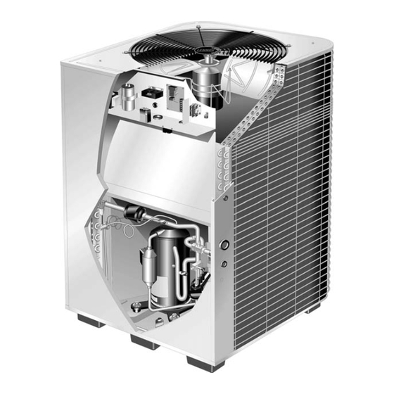
The HPXA19 is a high efficiency residential split−system
heat pump unit, which features a two−step scroll compres-
sor and R410A refrigerant. HPXA19 units are available in
2, 3 (−036 and −038 models), 4 and 5 ton sizes. The series
includes the HPXA19−038, a 3 ton unit equipped with a vari-
able speed condenser fan motor. The series is designed for
use with an expansion valve only (approved for use with
R410A) in the indoor unit.This manual is divided into sec-
tions which discuss the major components, refrigerant sys-
tem, charging procedure, maintenance and operation se-
quence.
Information contained in this manual is intended for use by
qualified service technicians only. All specifications are
subject to change.
IMPORTANT
Operating pressures of this R410A unit are higher
than pressures in R22 units. Always use service
equipment rated for R410A.
WARNING
Improper installation, adjustment, alteration, service
or maintenance can cause property damage, person-
al injury or loss of life. Installation and service must
be performed by a qualified installer or service
agency.
IMPORTANT
The Clean Air Act of 1990 bans the intentional vent-
ing of (CFC's and HFC's) as of July 1, 1992. Approved
methods of recovery, recycling or reclaiming must
be followed. Fines and/or incarceration my be levied
for noncompliance.
. . . . . . . . . . . . . . . . . . . . . . . . . . . . . . . . . . . . . .
Specifications / Electrical Data
. . . . . . . . . . . . . . . . . . . . . . . . . . . . . . . . . .
. . . . . . . . . . . . . . . . . . . . . . . . . . . .
. . . . . . . . . . . . . . . . . . . . . . . . . .
Corp. 0302−L2
Revised 07−2006
HPXA19 SERIES UNITS
Table of Contents
1
. . . . . . . . . . . . . . . . . .
2
3
3
16
Page 1
DANGER
Shock Hazard
Remove all power at disconnect be-
fore removing access panel.
HPXA19 units use single-pole con-
tactors. Potential exists for electrical
shock resulting in injury or death.
Line voltage exists at all components
(even when unit is not in operation).
. . . . . . . . . . . . . . . . . . . . . . . . . . . . . . . . . .
. . . . . . . . . . . . . . . . . . . . . . . .
. . . . . . . . . . . . . . . . . . . . . . . . . . . . . . .
VII Diagrams and Operating Sequence
HPXA19
18
22
22
. . . . . . . . . . .
23
© 2003 Lennox Industries Inc.
Advertisement

Subscribe to Our Youtube Channel
Related Manuals for Lennox HPXA19


Summary of Contents for Lennox HPXA19
-
Page 1: Table Of Contents
R410A refrigerant. HPXA19 units are available in 2, 3 (−036 and −038 models), 4 and 5 ton sizes. The series includes the HPXA19−038, a 3 ton unit equipped with a vari- able speed condenser fan motor. The series is designed for use with an expansion valve only (approved for use with R410A) in the indoor unit.This manual is divided into sec-... -
Page 2: General
SPECIFICATIONS General Model No. HPXA19−024 HPXA19−036 HPXA19−038 HPXA19−048 HPXA19−060 Data Nominal Tonnage (kW) 2 (7.0) 3 (10.6) 3 (10.6) 4 (14.1) 5 (17.6) Liquid line o.d. − in. (mm) 3/8 (9.5) 3/8 (9.5) 3/8 (9.5) 3/8 (9.5) 3/8 (9.5) Connections (sweat) Vapor line o.d. -
Page 3: I Application
Figure 2 shows the basic scroll form. Two iden- tical scrolls are mated together forming concentric spiral The scroll compressors in all HPXA19 model units are de- shapes (figure 3). One scroll remains stationary, while the signed for use with R410A refrigerant and operation at high other is allowed to orbit"... - Page 4 TWO−STAGE OPERATION stage operation. The compressor will operate on first−stage until demand is satisfied or the indoor temperature reaches The two−stage scroll compressor operates like any stan- the thermostat set point calling for second−stage. dard scroll compressor with the exception the two−stage Second−stage (high capacity) is achieved by blocking the compressor modulates between first stage (low capacity bypass ports (figure 5 bypass ports closed) with a slider...
- Page 5 INTERNAL SOLENOID (L34) Procedure 1. Turn main power "OFF" to outdoor unit. The internal unloader solenoid controls the two−stage op- 2. Adjust room thermostat set point above (heating op- eration of the compressor by shifting a slide ring mecha- eration on heat pump) or below (cooling operation) the nism to open two by−pass ports in the first compression room temperature 5ºF.
- Page 6 TABLE 1 Compressor Operation Unit Readings Y1 − Y2 − 1st-Stage Expected Results 2nd-Stage Compressor Voltage Same Amperage Higher Condenser Fan motor Amperage Same or Higher Temperature Ambient Same Outdoor Coil Discharge Air Higher in Cooling Lower in Heating Compressor Discharge Line Higher Indoor Return Air Same...
- Page 7 15°F. The compressor is energized by a contactor located in the control box. All HPXA19 units are single phase and use single− The switch closes when it is exposed to 55 psig and opens pole contactors.
- Page 8 I−High Pressure Switch (S4) Regional climatic conditions may require the control to be ad- justed to a different setting. The adjustment screw is located IMPORTANT on the control. A hole cut into the bottom shelf of the control box provides access to the control from the compressor Pressure switch settings for R410A refrigerant will compartment.
- Page 9 225° + 11°F. FIGURE P−Dual Capacitor (C12) The compressor and fan in HPXA19−024, −036, −048 and TABLE 3 −060 units use permanent split capacitor motors. A single dual" capacitor is used for both the fan motor and the com- HPXA19 UNIT "A"...
- Page 10 (cfm). The variable speed condenser fan motor (figure 14) used in all HPXA19−038 units is a three-phase, electronically controlled Motor rpm is continually adjusted internally to maintain d.c. brushless motor (controller converts single phase a.c. to constant static pressure against the fan blade.
- Page 11 S−Filter Drier bly. Installing the shields to close to the bearing hub will A filter drier designed for all HPXA19 model units is factory create noise and may affect operation. Installing too far installed in the liquid line. The filter drier is designed to re-...
- Page 12 The LSOM is not a safety component and cannot frost cycle is required. Two temperature probes are per- shut down or control the HPXA19. The LSOM is a monitoring device only. manently attached to the control. The coil temperature probe is designed with a spring clip to allow mounting to W−Crankcase Heater (HR1)
- Page 13 TABLE 5 System Operation Monitor LED Troubleshooting Codes Status LED Description Status LED Status LED Troubleshooting Information Green Power" Module has power. 24VAC control power is present at the module terminal. Compressor protector is open. Thermostat demand signal Outdoor unit power disconnect is open. Y1 is present, but the com- pressor is not running.
- Page 14 COIL SENSOR LOCATION During "Test" mode 5−Strike Lockout Feature HPXA19−036/−048/−060 The internal control logic of the board counts the pres- Coil sensor should be on sure switch trips only while the Y1 (Input) line is active. If the 5th hairpin from the a pressure switch opens and closes four times during a bottom on the outside loop.
- Page 15 TABLE 6 Defrost Control Board Diagnostic (5 strike) LED 1 LED 2 Condition Possible Cause(s) Solution Check control transformer power No power (24V) to board terminals (24V). R & C. Power problem If power is available and LED(s) are Board failure. unlit, replace board and all sensors.
-
Page 16: Refrigerant System
III−REFRIGERANT SYSTEM Field refrigerant piping consists of liquid and vapor lines All 2 ton HPXA19 units are equipped with a start capacitor from the outdoor unit (sweat connections). Use Lennox (C7). The capacitor is located in the control box and wired L15 series line sets as shown in table 7. - Page 17 A−Service Valves To Close Service Valve: 1 − Remove stem cap with an adjustable wrench. IMPORTANT 2 − Using service wrench and hex head extension, turn stem clockwise to seat valve. Tighten it firmly. Only use Allen wrenches of sufficient hardness (50Rc −...
-
Page 18: Charging
Vapor Line (Ball Type) Service Valve WARNING (Valve Open) Use Adjustable Wrench Fire, Explosion and Personal Safety To open: rotate stem counter-clockwise 90°. Hazard. To close: rotate stem clockwise 90°. Failure to follow this warning could service port result in damage, personal injury or unit side death. - Page 19 9 − When the absolute pressure requirement above has IMPORTANT been met, disconnect the manifold hose from the vacu- um pump and connect it to an upright cylinder of R410A Use a thermocouple or thermistor electronic vacuum refrigerant. Open the manifold gauge valves to break gauge that is calibrated in microns.
- Page 20 Approach Temperature Model Number Liquid Line Temp. − Outdoor Ambient °F (°C) Some R410A cylinders are equipped with a dip HPXA19−024 4.0 + 1 (2.2 + .5) tube that allows you to draw liquid refrigerant from HPXA19−036 7.0 + 1 (3.9 + .5) the bottom of the cylinder without turning the cyl- HPXA19−038...
- Page 21 TABLE 12 NORMAL OPERATING PRESSURES COOLING OPERATION (Liquid ±10 and Vapor ±5 psig) First Stage (Low Capacity) Outdoor Coil Outdoor Coil HPXA19−024 HPXA19−036 HPXA19−038 HPXA19−048 HPXA19−060 Entering Air Vapor Liquid Vapor Liquid Liquid Vapor Liquid Vapor Liquid Vapor Temp. °F (°C) 65 (18.3)
- Page 22 Table 14 R410A Temperature/Pressure Chart Temperature Pressure Temperature Pressure Temperature Pressure Temperature Pressure °F Psig °F Psig °F Psig °F Psig 100.8 178.5 290.8 445.9 102.9 181.6 295.1 451.8 105.0 184.3 299.4 457.6 107.1 187.7 303.8 463.5 109.2 190.9 308.2 469.5 111.4 194.1...
-
Page 23: Service And Recovery
Ensure power is off before cleaning. 2 − Outdoor unit fan motor is prelubricated and sealed. No If the HPXA19 system must be opened for any kind of ser- further lubrication is needed. vice, such as compressor or filter drier replacement, you must take extra precautions to prevent moisture from en- 3 −... - Page 24 VII−DIAGRAM / OPERATING SEQUENCE HPXA19−024, 036, −048 & −060 Page 24...
- Page 25 K1−1 N.O. closes, energizing compressor, outdoor fan sor contactor K1. motor and transformer T46. HPXA19−024 − Compressor begins start up. Relay 4− Heat demand energizes solenoid relay K195. K195−1 K31 remains closed during start up and capacitor closes sending voltage to rectifier plug D4. D4 con- C7 remains in the circuit.
- Page 26 HPXA19−038 with Variable Speed Motor Page 26...
- Page 27 Sequence of Operation HPXA19−038 B− Ambient temperature BELOW S23 low ambient setting. S23 closes shunting Y1 and Y2. First Stage Cool (low capacity) 1− Internal wiring de−energizes terminal O by heating Transformer from indoor unit supplies 24VAC power to mode selection, de−energizing the reversing valve. In- the thermostat and outdoor unit controls.
Need help?
Do you have a question about the HPXA19 and is the answer not in the manual?
Questions and answers