Table of Contents
Advertisement
E2002 Lennox Industries Inc.
Dallas, Texas, USA
HP27 Outdoor Unit
HP27 outdoor units are designed for expansion valve sys-
tems only. They are not designed for RFC systems. Refer to
Lennox engineering handbook for expansion valve kits
which you must order separately.
Shipping & Packing List
1 − Assembled HP27 outdoor unit
2 − Grommets (for liquid and vapor lines)
Check equipment for shipping damage. If you find any
damage, immediately contact the last carrier.
WARNING
Improper installation, adjustment, alteration, service
or maintenance can cause property damage, person-
al injury or loss of life. Installation and service must
be performed by a qualified installer or service
agency.
IMPORTANT
The Clean Air Act of 1990 bans the intentional vent-
ing of refrigerant (CFC's and HCFC's) as of July 1,
1992. Approved methods of recovery, recycling or
reclaiming must be followed. Fines and/or incarcera-
tion may be levied for noncompliance.
06/04
*2P0604*
®
Page 1
INSTALLATION
INSTRUCTIONS
HP27 SERIES UNITS
HEAT PUMP UNITS
504,712M
06/04
Supersedes 12/03
Table of Contents
. . . . . . . . . . . . . . . . . . . . . . . . . . . . .
. . . . . . . . . . . . . . . . . . . . . . . . . . . .
. . . . . . . . . . . . . . . . . . . . . . . . . . . . . . .
. . . . . . . . . . . . . . . . . . . . . . . . . . . . .
. . . . . . . . . . . . . . . . . . . . . . . . . . . . . . . .
. . . . . . . . . . . . . . . . . . . . . . . . . . . . . . . . . . . . . .
. . . . . . . . . . . . . . . . . . . . . . . . . . . . . .
. . . . . . . . . . . . . . . . . . . . . . . . . . . . . . . .
. . . . . . . . . . . . . . . . . . . . . . . . . . . . . . . . . .
. . . . . . . . . . . . . . . . . . . . . . . . . . . . . . . . . . .
. . . . . . . . . . . . . . . . . . . . . . . . . . . . . . . . . . . . . .
. . . . . . . . . . . . . . . . . . . . . . . . . . .
. . . . . . . . . . . . . . . . . . . . . . . . . . . . . . . . . . . . .
. . . . . . . . . . . . . . . . . . . . . . . . . . . . .
. . . . . . . . . . . . . . . . . . . . . . . . . . . . . . .
. . . . . . . . . . . . . . . . . . . . . . . . . . . . . . . . . .
. . . . . . . . . . . . . . . . . . . . . . . . . . . .
RETAIN THESE INSTRUCTIONS
FOR FUTURE REFERENCE
General Information
These instructions are intended as a general guide and do
not supersede local codes in any way. Consult authorities
having jurisdiction before installation.
WARNING
This product and/or the indoor unit it is matched with
may contain fiberglass wool.
Disturbing the insulation during installation, mainte-
nance, or repair will expose you to fiberglass wool
dust. Breathing this may cause lung cancer. (Fiber-
glass wool is known to the State of California to
cause cancer.)
Fiberglass wool may also cause respiratory, skin,
and eye irritation.
To reduce exposure to this substance or for further
information, consult material safety data sheets
available from address shown below, or contact your
supervisor.
Lennox Industries Inc.
P.O. Box 799900
Dallas, TX 75379−9900
Litho U.S.A.
. . . . . . . . . . . . . . . . . . . . . . . . .
. . . . . . . . . . . . . . . . . . . .
504,712M
*P504712M*
1
1
1
2
3
3
4
6
10
10
11
12
13
13
13
15
16
17
18
Advertisement
Table of Contents

Subscribe to Our Youtube Channel
Related Manuals for Lennox HP27 SERIES


Summary of Contents for Lennox HP27 SERIES
-
Page 1: Table Of Contents
HP27 outdoor units are designed for expansion valve sys- FOR FUTURE REFERENCE tems only. They are not designed for RFC systems. Refer to Lennox engineering handbook for expansion valve kits General Information which you must order separately. These instructions are intended as a general guide and do Shipping &... -
Page 2: Unit Dimensions
Unit Dimensions − inches (mm) INLET INLET COMPRESSOR INLET COIL DRAIN OUTLETS TOP VIEW (Around perimeter of base) 34-1/16 ELECTRICAL (865) 32−1/8 INLETS (816) DISCHARGE VAPOR LINE INLET 4-1/2 (114) 2-9/16 LIQUID (65) LINE INLET 7-1/2 7-1/2 2-3/4 13-5/8 (191) (191) 3-7/8 (70) -
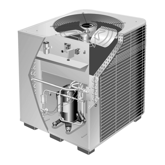
Page 3: Parts Arrangement
Parts Arrangement HP27 UNIT COMPONENTS DEFROST CONTROL/TIMED−OFF CONTROL DUAL CAPACITOR CONTACTOR SENSING BULB −036, −042 ONLY GROUND LUG SENSING BULB −024, −030 ONLY HIGH PRESSURE SWITCH BIFLOW FILTER/DRIER VAPOR GAUGE PORT EXPANSION VALVE WITH INTERNAL CHECK VALVE VAPOR LINE SERVICE VALVE AND GAUGE PORT DEFROST... -
Page 4: Electrical
4 − When you install the unit in areas where low ambient Roof Mounting temperatures exist, locate the unit so winter prevailing If you are unable to mount the unit coil away from prevailing winds do not blow directly into outdoor coil. winter winds, construct a wind barrier. - Page 5 NOTE − Units are approved for use only with copper WARNING conductors. 24V, Class II circuit connections are made in the low Unit must be grounded in accordance with national voltage junction box. Refer to figure 5 for field wiring and local codes.
-
Page 6: Refrigerant Piping
(Some connections may not apply. from the outdoor unit (sweat connections) to the indoor coil Refer to specific thermostat and indoor unit.) (flare or sweat connections). Use Lennox L15 (sweat, non- flare) series line sets as shown in table 1 or use field-fabri- Outdoor cated refrigerant lines. - Page 7 Refrigerant Line Sets How To Install Vertical Runs (new construction shown) NOTE - Similar installation practices should be used if line set is to be installed on exterior of outside wall. IMPORTANT - Refrigerant Outside Wall Vapor Line Liquid Line lines must not contact wall.
- Page 8 Refrigerant Line Sets: Installing Horizontal Runs To hang line set from joist or rafter, use either metal strapping material Wire Tie or anchored heavy nylon wire ties. (around vapor line only) 8 feet Floor Joist or Roof Rafter Tape or Wire Tie 8 feet Strapping Material (around vapor line only) Metal Sleeve...
- Page 9 Refrigerant Line Sets: Transition From Vertical To Horizontal Automotive Anchored Heavy Muffler-Type Nylon Wire Tie Hanger Wall Wall Stud Stud Strap Liquid Line Strap Liquid Line To Vapor Line To Vapor Line Liquid Line Vapor Line Metal Vapor Line Wrapped in Metal Sleeve Liquid Line...
-
Page 10: Refrigerant Metering Device
11 NM HP27 units are used in check expansion valve systems IMPORTANT only. See the Lennox Engineering Handbook for approved TXV match-ups and application information. Service valves are closed to the outdoor unit and Check expansion valves equipped with Chatleff fittings open to line set connections. -
Page 11: Leak Testing
3 − Replace the stem cap. Tighten finger tight, then tighten Vapor Line Service Valve an additional 1/6 turn. (Valve Open) To Close Service Valve: To open: rotate stem counter-clockwise 90_. 1 − Remove the stem cap with an adjustable wrench. To close: use adjustable wrench and rotate stem clockwise 90_. -
Page 12: Evacuation
2 − Connect micron gauge. WARNING 3 − Connect the vacuum pump (with vacuum gauge) to the center port of the manifold gauge set. Danger of explosion: Can cause equipment damage, 4 − Open both manifold valves and start the vacuum pump. injury or death. -
Page 13: Start−Up
The outdoor unit should be charged during warm weather. Start−Up However, applications arise in which charging must occur Cooling Start−Up in the colder months. The method of charging is deter- mined by the unit’s refrigerant metering device and the out- door ambient temperature. - Page 14 essary for checking the charge. Block equal sections of air 1 − Record outdoor ambient temperature using a digital thermometer. intake panels and move obstructions sideways until the liq- uid pressure is in the 200−250 psig (1379−1724 kPa) range. 2 − Attach high pressure gauge set and operate unit for See figure 15.
-
Page 15: System Operation
Table 6 Normal Operating Pressures HP27-024 HP27-030 HP27−036 HP27-042 Outdoor Coil Outdoor Coil Air Entering Mode liq. + vapor + liq. + vapor + liq. + vapor+ liq. + vapor + Temperature _F 10 psig 5 psig 10 psig 5 psig 10 psig 5 psig 10 psig... -
Page 16: Defrost System
High Pressure Switch across the TEST pins for two seconds, the control will enter the defrost mode. If the jumper is removed before an addi- The HP27 is equipped with an auto-reset high pressure tional 5−second period has elapsed (7 seconds total), the switch (single-pole, single-throw) which is located on the unit will remain in defrost mode until the defrost thermostat liquid line. -
Page 17: Maintenance
Defrost Control Board SERVICE HIGH PRESSURE LIGHT PRESSURE SWITCH SWITCH TERMINALS TERMINALS WIRING CONNECTIONS AMBIENT THERMISTOR High TERMINALS OPTIONAL Pressure PRESSURE Switch SWITCH (Factory−wired) TERMINALS (Remove factory− Optional DEFROST installed jumper Pressure INTERVAL to install TIMING PINS Switch pressure switch.) (Field−provided TERMINAL and installed −−... -
Page 18: Hp27 Check Points
1 − Clean or change the filters. Refer to the Engineering Handbook for optional accesso- 2 - Lennox blower motors are prelubricated and permanent- ries that may apply to this unit. The following may or may ly sealed. No more lubrication is needed.
Need help?
Do you have a question about the HP27 SERIES and is the answer not in the manual?
Questions and answers