
Related Manuals for Rheem MPs Series


Summary of Contents for Rheem MPs Series
-
Page 1: Installation Instructions
Installation Instructions Air Sourced Split Heat Pump Module MPs Series This water heater must be installed and serviced by an authorised person. Please leave this guide with the householder. - Page 2 Compliance Certificate. PATENTS This water heater may be protected by one or more patents or registered designs in the name of Rheem Australia Pty Ltd. TRADE MARKS ® Registered trademark of Rheem Australia Pty Ltd.
-
Page 3: Table Of Contents
CONTENTS HOUSEHOLDER – This installation instruction booklet is intended for the installer but you may find it of interest. Installation ....................4 Heat Pump And Tank Assembly ............11 Connections – Electrical ..............30 Commissioning ..................32 Water Supplies ..................36 Warranty Note .................. -
Page 4: Installation
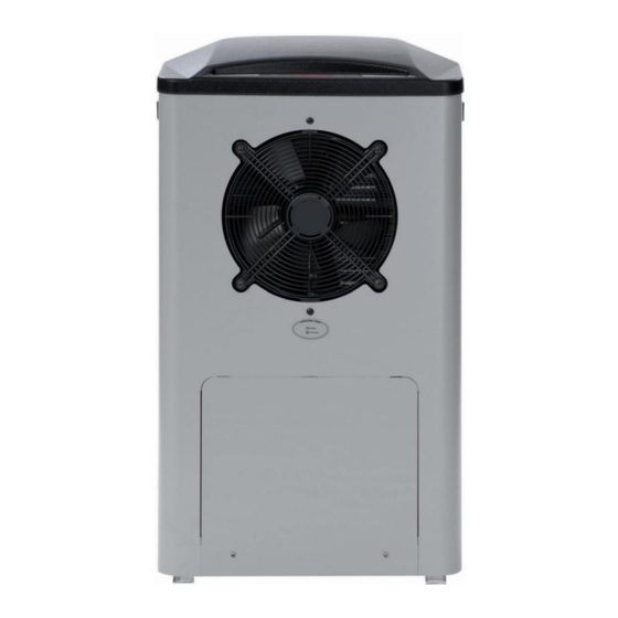
INSTALLATION THE HEAT PUMP MODULE OF THIS WATER HEATER IS FOR OUTDOOR INSTALLATON ONLY. The installation must comply with the requirements of AS/NZS 3500.4, AS/NZS 3000 and all local codes and regulatory authority requirements. In New Zealand, the installation must conform with Clause G12 of the New Zealand Building Code. - Page 5 INSTALLATION HEAT PUMP MODULE LOCATION The heat pump module is suitable for outdoor installation only. The heat pump module‟s position is to be chosen with noise, safety and service in mind. Make sure people (particularly children) will not accidentally touch the air inlet louvres and outlet grille and that they are clear of obstructions and shrubbery.
- Page 6 INSTALLATION Note These instructions cover only the installation of the heat pump module and the connections made between the heat pump module and storage tank. Refer to the Owner‟s Guide and Installation Instructions supplied with the storage tank for further information including: where and how to locate the heat pump water heater the dimensions of the heat pump water heater and any clearances required from surrounding objects...
- Page 7 INSTALLATION MAINS WATER SUPPLY Where the mains water supply pressure exceeds that shown in the table below, an approved pressure limiting valve is required. Refer to the Owner‟s Guide and Installation Instructions supplied with the storage tank for the position of the pressure limiting valve.
- Page 8 The refrigerant must not be vented to atmosphere. Phone your nearest Rheem Service Department or Accredited Service Agent to arrange for an inspection.
- Page 9 INSTALLATION DIMENSIONS AND TECHNICAL DATA elevation plan view PUMP DIMENSIONS - REMOTE 25 LITRE STORAGE TANK Heat pump module models 180536 (R) 180540 (E) Maximum rated power input watts 3600 Rated heat pump power input watts Booster element ratings 2.4, 3.6 Refrigerant type R134a Refrigerant circuit pressure...
- Page 10 INSTALLATION TYPICAL INSTALLATON – OUTDOOR LOCATION TYPICAL INSTALLATION HEAT PUMP WATER HEATER - REMOTE...
-
Page 11: Heat Pump And Tank Assembly
HEAT PUMP AND TANK ASSEMBLY STORAGE TANK AND HEAT PUMP MODULE The heat pump water heater is made of two main components, the storage tank and the heat pump module. For transport and handling (weight) purposes both items are shipped separately. The water heater must not be operated until both components are installed, connected and purged of air. - Page 12 HEAT PUMP AND TANK ASSEMBLY storage tank heat pump module There is a kit supplied with the heat pump module (PN 290123). The components supplied in the kit are: 290123 Kit Installation Heat Pump Module Split 126574 Installation instructions heat pump module split 126571 Easy start guide instructions heat pump module split 220522 Drain hose tube ½”...
- Page 13 HEAT PUMP AND TANK ASSEMBLY ASSEMBLY PROCEDURE Warning: The heat pump must be assembled, plumbed, filled with water and purged of air prior to power being connected and switched on. The following procedure is to be followed to install the heat pump module in position and connect to the heat pump storage tank.
- Page 14 HEAT PUMP AND TANK ASSEMBLY Drain Hose: Retrieve the drain hose, hose clamp, saddle and two black screws from the kit bag. Feed the hose through the penetration on the side of the heat pump module Slip the hose clamp over the upper end of the hose within the heat ...
- Page 15 HEAT PUMP AND TANK ASSEMBLY Heat Pump Module Location: Select the location for the heat pump module. The heat pump module must be positioned such that there is a clearance of at least 300 mm perpendicular from the air inlet louvres and the outlet grilles.
- Page 16 HEAT PUMP AND TANK ASSEMBLY Connection Side for Heat Pump Module: Select which side, either the left or right hand side, of the heat pump module will be used to connect the heat pump flow and return lines to the flexible braided hoses. It is recommended to select the side of the heat pump module which is closest to the heat pump storage tank.
- Page 17 HEAT PUMP AND TANK ASSEMBLY Step 8 assemble hose mount angle and hose clamp brackets Speed Fasteners: Retrieve the four (4) sheet metal speed fasteners from the kit bag. Clip one speed fastener over each of the four (4) holes, two (2) on ...
- Page 18 HEAT PUMP AND TANK ASSEMBLY 10. Rear Access Panel: Retrieve the heat pump module‟s rear access panel. Loosely position the two flexible braided hoses attached to the hose bracket assembly in the two tab cut outs. The „hot‟ flexible braided hose, marked with a red collar, should be in the top tab cut out.
- Page 19 HEAT PUMP AND TANK ASSEMBLY 11. Conduit Clamp: Retrieve the conduit clamp from the kit bag and fix it to the pilot hole above the rear access panel on the side which will be closest to the heat pump storage tank, using a screw provided. Locate the cable set conduit in the conduit clamp and close the ...
- Page 20 HEAT PUMP AND TANK ASSEMBLY 13. Template: Retrieve the heat pump module‟s carton liner piece, marked “(DO NOT REMOVE)”, from the original packaging. Position the heat pump module template, in an L shape, against the wall and slab or solid base. Mark the location on the slab or solid base, through the template, of ...
- Page 21 HEAT PUMP AND TANK ASSEMBLY 14. Dynabolts in Base: Drill four (4) x 8 mm holes in the slab or solid base. Insert the four (4) x 8 mm (M6) dynabolts provided, into the slab or solid base. Ensure the collar of the dynabolt does not protrude above the surface of the slab or solid base.
- Page 22 HEAT PUMP AND TANK ASSEMBLY 15. Wall Bracket: Drill a hole in the wall to receive a suitable anchor for the heat pump module wall bracket. Retrieve the heat pump wall bracket from the kit bag and fix to the ...
- Page 23 HEAT PUMP AND TANK ASSEMBLY 18. Wall Bracket Fixing: Fix the wall bracket tab to the wall bracket, using a screw provided. Ensure the wall bracket tab sits on top of the horizontal section of the wall bracket. Step 18 fix wall bracket tab to wall bracket 19.
- Page 24 HEAT PUMP AND TANK ASSEMBLY 20. Non Return and Air Bleed Valve Assembly: Connect the non return and air bleed valve assembly provided to the heat pump hot flow connection, marked “FROM HEAT PUMP” on the heat pump storage tank. The non return valve end of the assembly is screwed into the heat pump storage tank and the end of the hex nipple is exposed.
- Page 25 HEAT PUMP AND TANK ASSEMBLY 22. Heat Pump Circuit: Install the heat pump circuit flow and return pipes between the heat pump module and the heat pump storage tank. The pipe work between the storage tank and the heat pump module must be fully insulated with closed cell polymer insulation or similar of a minimum thickness of 13 mm.
- Page 26 HEAT PUMP AND TANK ASSEMBLY Step 22 connect insulated heat pump circuit insulate non return valve and pipe work to heat pump module air bleed valve assembly and heat pump storage tank 23. Lower Front Cover: Remove the two screws securing the lower front cover to the storage tank.
- Page 27 HEAT PUMP AND TANK ASSEMBLY 24. Cable Set Connection: Route the cable set from the heat pump module to the heat pump storage tank. Unscrew the gland nut from the gland on the cable set and insert the 3 plugs, wires and nut of the cable set through the hole on the right hand side of the electrical connection tab at the bottom of the lower front opening.
- Page 28 HEAT PUMP AND TANK ASSEMBLY 26. Mains Power Connection: Connect the mains power supply wiring to the terminal block and earth connection inside of the lower front cover. Secure the conduit to the side of the storage tank with a saddle. ...
- Page 29 HEAT PUMP AND TANK ASSEMBLY 29. Water Supply: Turn on the cold water supply and fill the water heater. “To Fill And Turn On The Water Heater” Refer to on page 32. It is important the heat pump circuit is purged of air, otherwise the system will not work effectively.
-
Page 30: Connections - Electrical
CONNECTIONS – ELECTRICAL The power supply to the water heater must not be switched on until the water heater is filled with water and a satisfactory megger reading is obtained. MEGGER READING When a megger test is conducted on this water heater, then the following should be noted. - Page 31 CONNECTIONS – ELECTRICAL WIRING DIAGRAM Electrical Circuit for Heat Pump – Robertshaw “ST” Thermostat...
-
Page 32: Commissioning
COMMISSIONING TO FILL AND TURN ON THE WATER HEATER The power supply to the water heater must not be switched on until the water heater is filled with water and a satisfactory megger reading is obtained. Open all of the hot water taps in the house (don‟t forget the shower). Connect a 6 mm diameter clear plastic hose to the spigot of the air bleed valve, located on the heat pump flow line at the connection to the storage tank. - Page 33 COMMISSIONING Note: The heat pump may not turn on after having just completed a heating cycle and more hot water is drawn from the water heater. The heat pump will wait until the compressor has cooled down and the conditions for start up are favourable, in order to protect the compressor from damage.
- Page 34 COMMISSIONING DIAGNOSTIC FEATURES OF THE HEAT PUMP CONTROLLER An operating mode monitor is located on the front of the heat pump module and houses a green and a red LED. The green LED, marked “NORMAL”, indicates the current operating mode of the heat pump water heater and the red LED, marked “ATTENTION”, indicates a fault mode.
- Page 35 COMMISSIONING Notes: Power must be available at the water heater and to the heat pump for the LEDs to glow or flash. Time controlled power supply If the water heater is connected to a time controlled power supply, then during periods of no power supply at the water heater the LEDs will be off.
-
Page 36: Water Supplies
WATER SUPPLIES This water heater must be installed in accordance with this advice to be covered by the warranty. This water heater is manufactured to suit the water conditions of most public reticulated water supplies. However, there are some known water chemistries which can have detrimental effects on the water heater and its operation and / or life expectancy. - Page 37 WATER SUPPLIES CHLORIDE AND PH Where the chloride level exceeds 250 mg/L warranty does not apply to the water heater. In a high chloride water supply, the water can corrode stainless steel parts and cause them to fail. Where the pH is less than 6.0 warranty does not apply to the water heater. pH is a measure of whether the water is alkaline or acid.
- Page 38 This page is intentionally blank.
-
Page 39: Warranty Note
WARRANTY NOTE The heat pump water heater is covered by a comprehensive warranty. For full warranty details, refer to the Owner‟s Guide and Installation Instructions supplied with the storage tank. The part extracts from the Warranty Condition (5) and warranty exclusions (c), (d), (e), (f) and 2 of the water heater warranty should be noted before commencing the installation. - Page 40 Revision Date: 2009 November 126574C...
Need help?
Do you have a question about the MPs Series and is the answer not in the manual?
Questions and answers