Table of Contents
Advertisement
Quick Links
OPERATORS MANUAL
QUICK START
If you are one of those people who think owner's manuals are included with a product to help absorb shock and vibra-
tion during shipment, you are a lot like we are. This section is for you. You want to fire up your equalizer without wading
through a bunch of stuff in manuals. Great. Read on. We'll keep it short.
Set the input LEVEL control to about 6. This is approximately unity gain in the BOOST/CUT mode. (In the CUT-
ONLY mode the level control should be set to 2 for unity gain.) Your sound system should be set up such that gain or loss
is not required in the equalizer(s). Set the EQ MODE switch on the rear for the desired operating mode, CUT-ONLY or
BOOST/CUT. The LEDs on the front illuminate, telling you which mode you are in. Set the OUTPUT MODE switch on
the rear for the desired output coupling mode (ACTIVE or TRANSFORMER COUPLED). Adjust the LOW CUT and
HIGH CUT FILTER controls on the front for the desired low and high cut frequencies. Full counterclockwise on the
LOW CUT control and full clockwise on the HIGH CUT control essentially defeats these functions.
If you read only this section, we assume you know how to set up an equalizer. So set the sliders where you want them
and you're outta here.
Never connect anything except an RS 1 or other approved Rane AC power supply to the thing that looks like a
telephone jack on the rear of the GE 30. This is an AC input and requires some special attention if you do not have an
operational power supply EXACTLY like the one that was originally packed with your unit. See the full explanation of the
power supply requirements elsewhere in this manual.
GE 30 CONNECTION
When connecting the GE 30 to other components in your
system for the first time, leave the power supply for last. This
will give you a chance to make mistakes and correct them
before any damage is done.
INPUTS on the GE 30 are balanced. They may be
connected for either balanced or unbalanced operation. This
product offers the choice between going in and out of it using
either the 3-pin connectors or the handsome black #6 terminal
strips with the finely plated screws. We will describe here the
use of the 3-pin connectors. The terminal strips are connected
in parallel and are used in the same way. Only the names have
been changed. Pin 2 is hot "+", pin 3 is return "–", and pin 1
is chassis ground. Balanced inputs require the use of pins 2
and 3. Pin 1 is unnecessary unless you are using it for shield
ground. For unbalanced operation, pins 1 and 3 must be
shorted together to prevent 6 dB of gain reduction. Drive pin
2 as hot and the combination of 1 and 3 as ground.
WEAR PARTS: This product contains no wear parts.
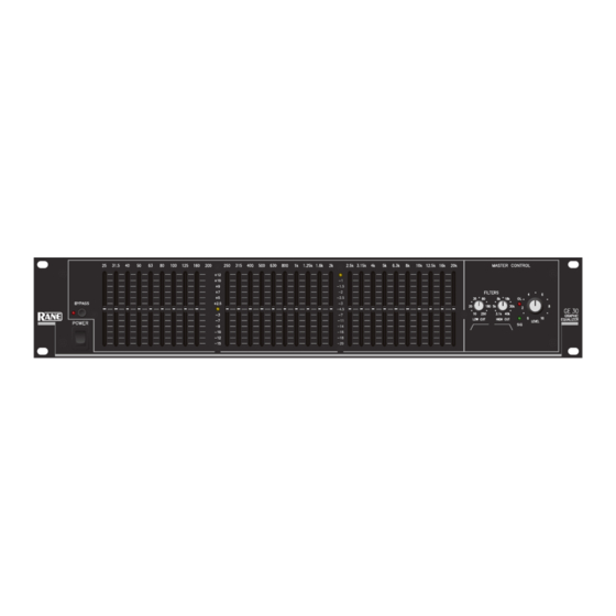
GRAPHIC EQUALIZER
OUTPUTS are balanced as well and follow the same
convention as the inputs. There are some tricky things to be
careful of at the output. If active balanced operation is your
preference, hot "+" and return "–" should be all that is
required. It does not take three wires to conduct a signal from
one unit to the next. Connect the shield to case or chassis
ground. Transformer balanced outputs are connected in the
same manner. Active unbalanced output requires "+" and
ground only. Use pins 2 and 1 respectively. In this mode, do
not short pins 1 and 3. If, however, you are using the trans-
former coupled mode and are running unbalanced, do short
pins 1 and 3 or you will get little or no output. In case you
haven't noticed, if you plan on throwing the selector switch
very often it's a good idea to connect everything in a balanced
configuration.
GE 30
Manual-1
Advertisement
Table of Contents

Related Manuals for Rane GE 30


Summary of Contents for Rane GE 30
-
Page 1: Graphic Equalizer
Never connect anything except an RS 1 or other approved Rane AC power supply to the thing that looks like a telephone jack on the rear of the GE 30. This is an AC input and requires some special attention if you do not have an operational power supply EXACTLY like the one that was originally packed with your unit. -
Page 2: Front Panel Description
LEVEL sets the Level of the signal coming into the GE 30. Turn this control down if the OVERLOAD LED lights up steadily (meaning too strong an Input signal). Since actual unity gain depends on varying slider settings (which is why we have not marked a unity gain position on the front panel), use the BYPASS switch to determine the exact unity gain position of this LEVEL control by comparing EQ and BYPASS loudness. -
Page 3: Rear Panel Description
BOOST/CUT mode, which reconfigures the LEDs on the front panel. Remote power supply input. Use only an RS 1 or other remote AC power supply approved by Rane. The GE 30 is supplied from the factory with a remote power supply suitable for connection to this input jack. It is not a telephone jack. The power requirements of the GE 30 calls for an 18-24 volt AC center-tapped transformer only. -
Page 4: Operating Instructions
This is exactly why the GE 30 offers the options it does. There are situations where a person of the Cut-Only persuasion needs to use the “other”...
Need help?
Do you have a question about the GE 30 and is the answer not in the manual?
Questions and answers