Lectronix R5000 Installation Instructions Manual
Lectronix r5000 installation instructions
Hide thumbs
Also See for R5000:
- Operating instructions manual (53 pages) ,
- Quick start manual (2 pages)

Subscribe to Our Youtube Channel
Related Manuals for Lectronix R5000


Summary of Contents for Lectronix R5000
- Page 1 R5000 Installation Instructions for RV’s Read these instructions carefully before installing this product and keep this manual for future reference.
- Page 2 © 2006, 2007 Lectronix, Inc. 16733-A.0...
- Page 3 Failure to properly focus on the operation of your motor vehicle can result in death, serious injury and property damage. This R5000 device should never be used at a time or in a manner that distracts you from properly focusing on operation of the motor vehicle in which it is installed.
-
Page 4: Table Of Contents
Adjusting the Display........................9 Installation of the R5000 ......................10 Dimensions of the R5000 ......................10 Wiring the R5000 Unit to the Vehicle’s Power and Speakers ..........13 Diagram of the Rear Connection of the R5000 ................ 13 Operation instructions ......................13 Sirius Satellite Radio........................ - Page 5 Common Problems........................29 Appendix A: One Year Limited Warranty .................. 31 Appendix B: Service and Technical Support................32 Contact Lectronix, Inc....................... 32 Appendix D: R5000 Coach Adapter Cable ................33 Appendix E: Tire Pressure Monitoring Option ................. 35 Sensor Specifications....................... 35...
-
Page 7: Safety Information
IMPORTANT SAFETY INFORMATION Safety Information Read the operating instructions for the R5000 and all other components of the system carefully before using the system. They contain instructions about how to use the system in a safe and effective manner. FAILURE TO OBSERVE THE INSTRUCTIONS GIVEN IN THIS MANUAL MAY CAUSE INJURY OR DAMAGE AND VOID THE WARRANTY. -
Page 8: Important Safety Information
IMPORTANT SAFETY INFORMATION Warning Observe the following warnings when installing. • Disconnect the lead from the negative (–) battery terminal before installation. Wiring and installation with the negative (–) battery terminal connected may cause electrical shock and injury due to a short circuit. Some vehicles equipped with the electrical safety system have specific procedures of battery terminal disconnection. -
Page 9: Cautions
IMPORTANT SAFETY INFORMATION Cautions FOLLOW THE LAWS AND REGULATIONS OF YOUR Caution STATE, PROVINCE OR COUNTRY FOR INSTALLATION. THIS PRODUCT IS A CLASS I LASER PRODUCT. Caution USE OF CONTROLS OR ADJUSTMENTS OR PERFORMANCE OF PROCEDURES OTHER THAN THOSE SPECIFIED HEREIN MAY RESULT IN HAZARDOUS RADIATION EXPOSURE. -
Page 10: Getting Started
† A subscription is required to use this service. Garmin GVN 52 Owner’s Manual If your R5000 includes the optional Garmin GVN 52 navigation system, please refer to the Garmin GVN 52 Owner’s Manual included with your vehicle for information regarding the... -
Page 11: Satellite Radio User's Guide
The R5000 will then automatically transition to the most recent Application and Function. Standby Operation The R5000 will be placed in a standby state for approximately 15 minutes when the vehicle’s ignition key is turned off. When ignition is restored, the system will immediately return to the last... -
Page 12: Selecting Applications And Functions
Each Application (i.e., Audio, Camera, Information or Navigation) includes a subgroup of Functions which you select using the Application controls and four-way arrow keys on the front of the R5000. The following table describes the Applications and lists their related Functions. 1) Select an Application by pressing an Application key. -
Page 13: The R5000 Display
INTRODUCTION The R5000 Display The R5000 display is divided into four windows as shown below. When you select a new Application and Function, the information associated with the current Application and Function may automatically move from the Active Window to the Background or Audio Windows. -
Page 14: Using The Sound Controls
3) Use the UP or DOWN arrow key to select the parameter for adjustment. 4) Use the LEFT or RIGHT arrow key to adjust the selected parameter. 5) When finished, press the MENU button again. R5000 Sound Buttons & Controls... -
Page 15: Adjusting The Display
4) Use the LEFT or RIGHT arrow key to adjust the selected parameter. 5) When finished, press the MENU button again. 6) The R5000 has the ability to output video to an external monitor. The Video Output selection is used to select this output from the following options: •... -
Page 16: Installation Of The R5000
Installation R5000 Installation of the R5000 If the Coach has a Camera Monitor System, this is the ideal location for the R5000 Unit. The R5000 unit is approximately the same size as most camera monitoring systems. If your Coach does not have a Camera Monitor System, you may have to do some dash modifications. Choose an appropriate place on the dash where the unit will not interfere with your view of the road. - Page 17 Remove the camera monitor system. You may be able to use the existing monitor mounting bracket for the R5000. Position the R5000 in the mounting bracket so that it is in the center of the monitor opening. Install the R5000 unit in the opening so that it is positioned flush to the faceplate and on a good viewing angle to the driver.
- Page 18 R5000 adapter cable. If there is a cable available for your coach you can plug directly into this connector(s). If not, by using the universal adapter cable, you will need access to the individual wires to connect to vehicle power and speaker connections.
-
Page 19: Wiring The R5000 Unit To The Vehicle's Power And Speakers
2) If there is not a direct connect interface harnesses available for your Coach, you may use the R5000 generic interface harness (Lectronix Inc. Part #16088 A.0) Refer to Appendix D of this manual for a drawing of the generic cable harness for wiring the R5000 into your coach. -
Page 20: Sirius Satellite Radio
The interface cable that connects the Sirius system to the R5000 system should be provided with the Sirius system. Check with your system provider for the correct interface cable, if the wrong cable is provided. (Refer to the diagram of the Rear Connections of the R5000 for plug in location.) -
Page 21: Reference Picture For Mounting Location Of Satellite Antenna
Sirius Satellite Radio Reference Picture for Mounting Location of Satellite Antenna: (Roof of RV Coach) Operation instructions Refer to the R5000 Operating Instructions for information on using your Sirius Radio. -
Page 22: Camera System (Cam)
Once installed, attach the camera connector to the cable connector at the rear of the coach. Once the R5000 unit is installed and the camera is connected, position the camera in the mounting bracket to give the... -
Page 23: Installation Instructions For The Sony Side Camera System
Camera System Installation instructions for the Sony Side Camera System Side camera installation is detailed in the pictures below. Decide on an appropriate spot on the sides of the front of your coach to mount the cameras where they will have an unobstructed view of the side of the coach and where they will not interfere with entrance doors and other coach features. - Page 24 Camera System 3) Seal for Water Protection 4) Housing Attachment...
- Page 25 7) After mounting the cameras, add the camera extension cables and route them to the back of the R5000 system, making sure not to stretch or route the cables by anything that will crimp, pinch, burn or do any other damage. (Refer to the diagram of the Rear...
-
Page 26: Reference Pictures For Mounting Location Of The Side Cameras
Camera System Reference Pictures for Mounting Location of the Side Cameras:... -
Page 27: Painting Recommendations For Sony Side Camera's
Camera System Painting Recommendations for Sony Side Camera’s Operation instructions Refer to the R5000 Operating Instructions for information on using your Camera System. -
Page 28: Tire Pressure Antenna Mounting Location
Tire Pressure System Tire Pressure Antenna Mounting Location The proper mounting location for the Tire Pressure Antenna is just in front of rear axle. -
Page 29: Mounting The Tire Pressure Antenna To The Vehicle
Bring the Antenna cable up the front of the vehicle and feed it thought the firewall, and route it to the back of the R5000 system. -
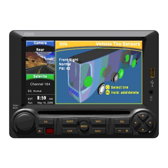
Page 30: Tire Pressure Monitor (Tires)
Tire Pressure System Tire Pressure Monitor (Tires) Using the optional tire pressure sensors installed on each tire, the R5000 can monitor the vehicle’s tire pressure and alert you to possible tire pressure problems. Tire Pressure Monitor Controls & Buttons Tire Pressure Sensor Operation Tire pressure is monitored approximately every 5 minutes with sensors placed on each tire. -
Page 31: Installing Tire Pressure Sensors
Tire Pressure System Installing Tire Pressure Sensors The sensors determine operating pressure of the tire when the sensor is first installed. Therefore the tire pressure at the time of installation is CRITICAL! All tires MUST be inflated to the manufacturer’s recommended cold pressures while the tires are cold. Refer to the owner’s manual. -
Page 32: Removing Tire Pressure Sensors
Tire Pressure System Removing Tire Pressure Sensors 1) Press the INFO button repeatedly until Tires is highlighted. 2) Press SEL or wait until Tires is automatically selected. 3) Using the FOUR-WAY arrow keys, select the tire where the tire pressure sensor is to be removed. -
Page 33: Garmin Navigation
The standard Garmin wiring harness (supplied with a Garmin GVN-52 not supplied by Lectronix) will not work with the R5000 system. If you did not purchase your Garmin unit from Lectronix, contact us to obtain the correct cable. (Refer to the diagram of the Rear Connections of the R5000 for plug in location.) -
Page 34: Maintenance
Maintenance Your product is designed and manufactured to ensure a minimum of maintenance. Cleaning hints follow. Keep the display clean of dust and debris. 2) Use a dry soft cloth for routine exterior cleaning. Never use benzene, thinner or other solvents. -
Page 35: Troubleshooting
Lectronix, Inc (see Appendix B). Only qualified personnel should service the product. Always refer diagnostics and repair to professionals. Lectronix, Inc. shall not be liable for any accidents arising out of neglect or attempts to repair the unit. - Page 36 CD Problems Problem Possible Cause Possible Solution No playback The disc is inserted upside down. Insert the disc correctly. No playback There is a flaw or foreign object on the Remove the foreign object, or use disc. a flawless disc. Sound skipping There is a flaw or foreign object on the Remove the foreign object, or use...
-
Page 37: Appendix A: One Year Limited Warranty
Appendix A: One Year Limited Warranty This R5000 is warranted to be free from defects in material or workmanship for one year from the date of purchase. During this period, Lectronix, Inc. will replace any R5000 that fail in normal use where used in accordance with this users’... -
Page 38: Appendix B: Service And Technical Support
Appendix B: Service and Technical Support There are no user serviceable components within the R5000. Service is provided by Authorized Service providers only. Contact Lectronix, Inc. For help or service, contact Lectronix, Inc. at 1-888-423-1183. When contacting Lectronix, please have the following system information on hand. To obtain the system information: 1) Press the MENU button. -
Page 39: Appendix D: R5000 Coach Adapter Cable
Appendix D: R5000 Coach Adapter Cable... -
Page 41: Appendix E: Tire Pressure Monitoring Option
Appendix E: Tire Pressure Monitoring Option The R5000 includes the RF receiver needed to monitor the tire pressure sensors. The setup, control, and monitoring is all done from the R5000 LCD display. Contact Lectronix, Inc. to purchase the optional Tire Pressure monitoring kit or additional sensors (see Appendix B for contact information).
Need help?
Do you have a question about the R5000 and is the answer not in the manual?
Questions and answers