Table of Contents
Advertisement
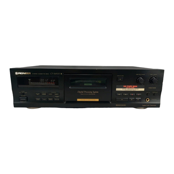
STEREO CASSETTE DECK
CT-S670D
THIS MANUAL IS APPLICABLE TO THE FOLLOWING MODEL(S) AND TYPE(S).
Model
Type
CT-S670D
HYXJ
CONTENTS
1. SAFETY INFORMATION .................................... 2
2. EXPLODED VIEWS AND PARTS LIST ............. 3
3. SCHEMATIC DIAGRAM ................................... 10
4. PCB CONNECTION DIAGRAM ....................... 20
5. PCB PARTS LIST ............................................. 27
6. ADJUSTMENT .................................................. 30
PIONEER ELECTRONIC CORPORATION
PIONEER ELECTRONICS SERVICE, INC. P.O. Box 1760, Long Beach, CA 90801-1760, U.S.A.
PIONEER ELECTRONIC (EUROPE) N.V . Haven 1087, Keetberglaan 1, 9120 Melsele, Belgium
PIONEER ELECTRONICS ASIACENTRE PTE. LTD. 501 Orchard Road, #10-00 Lane Crawford Place, Singapore 0923
PIONEER ELECTRONIC CORPORATION 1998
D
TIMER
REC
OFF
POWER
-OFF _ON
Power Requirement
AC220-230V
4-1, Meguro 1-Chome, Meguro-ku, Tokyo 153-8654, Japan
Ωı¿∫>≥?Û
Î
STEREO CASSETTE DECK
OPEN/CLOSE
0
Digital
Digital Processing System
DISP OFF
COUNTER
PLAY
/RPT
20bit A/D•D/A CONVERTER
DOLBY
METER
1
¡
NR
RANGE
MODE
RESET
SOURCE
/TAPE
DIGITAL
DIGITAL
3
8
FLEX
MONITOR
NR
INPUT
DOLBY B-C NR HX PRO
7. GENERAL INFORMATION .............................. 33
7.1 PARTS ....................................................... 33
7.1.1 IC ...................................................... 33
7.1.2 DISPLAY .......................................... 35
7.2 DIAGNOSIS ................................................ 36
7.2.1 DISASSEMBLY ................................ 36
7.2.2 TEST MODE ..................................... 36
7.3 BLOCK DIAGRAM ...................................... 39
....................................................... 40
REC BALANCE
REC LEVEL
5
4
6
3
7
2
8
1
9
0
10
L
R
CD-DECK SYNCHRO
DIGITAL/CD
BLE XD
SYNCHRO
ORDER NO.
•
7
PHONES
Legato Link Conversion
RRV1955
Remarks
T-DZR APR. 1998 Printed in Japan
Advertisement
Table of Contents

Related Manuals for Pioneer CT-S670D


Summary of Contents for Pioneer CT-S670D
-
Page 1: Table Of Contents
PIONEER ELECTRONICS SERVICE, INC. P.O. Box 1760, Long Beach, CA 90801-1760, U.S.A. PIONEER ELECTRONIC (EUROPE) N.V . Haven 1087, Keetberglaan 1, 9120 Melsele, Belgium PIONEER ELECTRONICS ASIACENTRE PTE. LTD. 501 Orchard Road, #10-00 Lane Crawford Place, Singapore 0923 PIONEER ELECTRONIC CORPORATION 1998... -
Page 2: Safety Information
For the latest information, always consult the current Also test with plug reversed PIONEER Service Manual. A subscription to, or ad- (Using AC adapter ditional copies of, PIONEER Service Manual may be plug as required) obtained at a nominal charge from PIONEER. -
Page 3: Exploded Views And Parts List
CT-S670D 2. EXPLODED VIEWS AND PARTS LIST NOTES : Parts marked by “ NSP ” are generally unavailable because they are not in our Master Spare Parts List. mark found on some component parts indicates the importance of the safety factor of the part. - Page 4 CT-S670D 2.2 EXTERIOR To Mechanism Unit Refer to " 2.3 FRONT PANEL SECTION".
- Page 5 CT-S670D EXTERIOR PARTS LIST Mark No. Description Part No. MAIN UNIT RWZ4279 TRN 2 UNIT RWZ4281 Strain Relief CM–22B Fuse (FU801: T1.25A) AEK1055 AC Power Cord PDG1058 Power Transformer RTT1345 (AC220–230V) Main Chassis RNB1132 Rear Panel RNA2199 PCB Spacer PNY–404...
- Page 6 CT-S670D 2.3 FRONT PANEL SECTION Froil PN397 Not used No. 33 Cut Part Froil PN397 19 (1/3) Refer to 19 (3/3) " 2.4 MECHANISM UNIT ". 19 (2/3) 19 (1/3) 19 (2/3) 19 (3/3) No. 19 Cut Part 23 (1/2)
- Page 7 CT-S670D FRONT PANEL SECTION PARTS LIST Mark No. Description Part No. FL UNIT RWX1146 OPSW UNIT RWX1142 FFC 33P (60V) RDD1400 Mechanism Unit RYM1271 DC Motor/0.75W PXM1010 Rubber Belt PEB1127 Motor Pulley PNW1634 Pulley Gear RNK1517 Spring RBK1004 Arm Gear...
- Page 8 CT-S670D 2.4 MECHANISM UNIT SECTION This screw No. 44 is the part to hold the cam gear for servicing, when the hook holding the cam gear No. 24 is broken.
- Page 9 CT-S670D MECHANISM UNIT SECTION PARTS LIST Mark No. Description Part No. FIXED CORE RLA1130 PLUNGER RLA1132 HEAD (R/P) RPB1047 HEAD (E) RPB1060 PUSH SW RSG1018 MTR REEL BLK RXM1057 MTR MAIN BLK RXM1058 SOLENOID BLK RXP1010 PHOTO-TRANSISTOR SPI33534FG MAIN BELT...
-
Page 10: Schematic Diagram
CT-S670D Note: When ordering service parts, be sure to refer to "EXPLODED VIEWS and PARTS LIST" or "PCB PARTS LIST". 3. SCHEMATIC DIAGRAM 3.1 OVERALL SCHEMATIC DIAGRAM LED UNIT POCM UNIT CN702 (3/4) (RWX1143) AKB7015 (RWZ4282) CN702 (4/4) D20PWY0510G PG02MR-F30... - Page 11 CT-S670D 1/2, OPSW UNIT (RWX1142) D20PWY0610G D20PWY0310G 52147-0610 CN702 (1/4) AKB7015 CN702 (2/4) AKB7015 JA911 JA912 1/4 to MAIN UNIT JA1801 (RWZ4279) GPIF32R JA901 JA601 TRN 2 UNIT (RWZ4281) POWER PWSW UNIT TRANSFORMER RTT1345 (RWZ4280) DXWW0315E AC POWER CORD PDG1058...
- Page 12 CT-S670D 3.2 MAIN UNIT (1/4) AND OPSW UNIT (1/2) PB AMP BIAS TRAP PB LEVEL ADJ. MECHA UNIT (1/4) (RYM1271) DOLBY B/C NR P. B HEAD RPB1047 (1/2) DOLBY CONT MAIN UNIT (1/4) (RWZ4279) : PLAYBACK SIGNAL ROUTE : RECORDING SIGNAL ROUTE...
- Page 13 CT-S670D TAPE/SOURCE/REC MONI LINE OUT BUFFER LINE HP AMP PB/REC METER AMP REC AMP...
- Page 14 CT-S670D 3.3 MAIN UNIT (2/4) MAIN UNIT (2/4) (RWZ4279) LRCK, BCLK (FROM DIR) ON/OFF NOTE If the parts are not identified in the diagram the followings are used. mark found on some component parts indicates the importance of the safety factor of the part. Therefore, when replacing, be sure to use parts of...
- Page 15 CT-S670D X'TAL/VCO X'TAL X1731: 18.432 MHz...
- Page 16 CT-S670D 3.4 MAIN UNIT(3/4), PWSW UNIT AND TRN2 UNIT MAIN UNIT (3/4) POWER SUPPLY (RWZ4279) S5688G 10/50 S5688G S5688G EARTH METAL FITTING S5688G CAUTION: FOR CONTINUED PROTECTION AGAINST RISK OF FIRE. REPLACE ONLY WITH SAME TIME NO. ICP-N15, MFD BY ROHM CO., LTD.
- Page 17 CT-S670D MECHA UNIT (3/4) (RYM1271) (RPB1060) BIAS OSC 160 kHz HX PRO BIAS CONTROL D/A CONVERTER BLEXD CONT NOTE If the parts are not identified in the diagram the followings are used. mark found on some component parts indicates the importance of the safety factor of the part.
- Page 18 CT-S670D 3.5 MAIN UNIT (4/4), OPSW UNIT (2/2), FL UNIT, LED UNIT AND POCM UNIT MAIN UNIT (4/4) (RWZ4279) NOTE If the parts are not identified in the diagram the followings are used. MEMORY mark found on some component parts indicates the importance of the safety factor of the part.
- Page 19 CT-S670D MECHA CONTROL POCM UNIT (RWZ4282) µ-COM LED UNIT (RWX1143)
-
Page 20: Pcb Connection Diagram
CT-S670D 4. PCB CONNECTION DIAGRAM NOTE FOR PCB DIAGRAMS: Symbol in PCB Symbol in Schematic Part Name 1. Part numbers in PCB diagrams match those in the schematic Diagrams Diagrams diagrams. 2. A comparison between the main parts of PCB and schematic diagrams is shown below. - Page 21 CT-S670D 4.2 PWSW UNIT, TRN2 UNIT AND TRN1 PCB TRN2 UNIT SIDE A TRN1 PCB J1001 POWER TRANSFORMER J1003 PWSW UNIT NEUTRAL LIVE AC POWER CORD PNP1725–A...
- Page 22 CT-S670D 4.3 MAIN UNIT MAIN UNIT Q1001 J1002 Q1003 IC1003 J1004 IC1001 Q1002 Q1004 IC1012 IC1004 Q753 Q351 IC1013 CN1502 IC1821 IC1011 Q531 IC1014 Q1731 Q1005 Q572 Q571 IC591 IC801 Q801 Q807 MECHA UNIT CN82 J1532 MECHA UNIT CN81 RNP1725–A...
- Page 23 CT-S670D SIDE A Q751 Q752 Q902 IC753 IC752 IC301 IC601 Q301 IC751 Q302 Q271 VR102 IC202 Q102 IC201 IC101 Q101 VR101 MECHA UNIT PB HEAD IC251 Q401 IC701 Q403 Q701 Q211 MECHA IC451 Q213 UNIT ERACE HEAD J701 MECHA UNIT...
- Page 24 CT-S670D MAIN UNIT IC1801 IC1751 IC1701...
- Page 25 CT-S670D SIDE B IC1802 IC1761 IC1741 IC1851 IC1731 IC501 IC551 RNP1725–A...
- Page 26 CT-S670D SIDE A 4.4 OPSW UNIT AND FL UNIT OPSW UNIT CN1601 CN701 FL UNIT CN1501 RNP1724–A...
-
Page 27: Pcb Parts List
CT-S670D 5. PCB PARTS LIST NOTES : Parts marked by “ NSP ” are generally unavailable because they are not in our Master Spare Parts List. mark found on some component parts indicates the importance of the safety factor of the part. - Page 28 CT-S670D Mark No. Description Part No. Mark No. Description Part No. CAPACITORS C1762, C1801, C1822, C1839, C761 CKSQYF104Z25 C1712, C1805, C1833, C801, C802 CKSQYF473Z50 C459, C460 CCCSL271K2H C906 CKSQYF473Z50 C1834 CCSQCH100D50 C101, C102 CQHA331J2A C103, C104, C115, C116 CCSQCH101J50 C119, C120, C463, C707...
-
Page 29: Led Unit
CT-S670D Mark No. Description Part No. Mark No. Description Part No. JA911, JA912 REMOTO JACK RKN1004 LED UNIT CN102, CN302 SP CONNECTOR B3B-PH-K-S JA901 MINI JACK PKN1005 SEMICONDUCTORS J1003 2m/m PITCH WIRE 6P D20PWW0615G D1531–D1533 (PURE GREEN ) MBG5074X J1001... -
Page 30: Adjustment
CT-S670D 6. ADJUSTMENT Adjustment points and Measurement points are shown in Fig. 6–5. 6.1 MECHANICAL ADJUSTMENT Tape Speed Adjustment Specifications/Ratings Mode Test Tape Adjusting Point Remarks (Playback Frequency) 3000Hz ± 5Hz PLAY NCT-111 (3kHz) Capstan Motor Note) Always use a ceramic screwdriver for adjustment. - Page 31 CT-S670D PLAY BACK RECORDING 12.5k 12.5k 315 Hz = 0 dB 315 Hz = 0 dB Fig. 6–2 Frequency Response Zone 6.2.1 Playback Section (1) Head Azimuth Adjustment Turn VR101 and VR102 to mechanical center position. Adjustment Measurement Adjustment No. Mode...
- Page 32 CT-S670D (2) Recording Bias and Recording Level Automatic Adjustment Press the MODE key, RESET key and the PAUSE key together to enter the into test mode. ‘ Press the MODE key, PAUSE key and the MUTE key together to clear all memory data. At this time, “CLR” is displayed on the counter.
-
Page 33: General Information
CT-S670D 7. GENERAL INFORMATION 7.1 PARTS ¶ The information shown in the list is basic information and may not correspond exactly to that shown in the schematic diagrams. 7.1.1 IC PD5431A (IC501: MAIN UNIT) System Control Micro-computer Pin Function Name... - Page 34 CT-S670D PD5431A Name Description Name Description FL grid terminal 1 ASE1 Analog switch control terminal 1 FL grid terminal 2 ASE0 Analog switch control terminal 0 FL grid terminal 3 Power supply terminal (built-in pull-down resistor) FL grid terminal 4...
-
Page 35: Display
CT-S670D 7.1.2 DISPLAY RAW1163 (V1501: FL UNIT) FL Tube ¶ Pin Assignment Note 1) F1, F2..Filament 2) NP .....No Pin 3) NC ... No Connection 4) DL .... Datum Line ¶ Pin Connection 5) 1G–10G..Grid ¶ Grid Assignment... -
Page 36: Diagnosis
CT-S670D 7.2 DIAGNOSIS 7.2.1 DISASSEMBLY Removing the Door Plate Catch the door plate with your fingers and pull it to the front. 7.2.2 TEST MODE (1) Entering the Test Mode While mechanism is stop, press the MODE key, RESET key and PAUSE key together to enter the test mode. - Page 37 CT-S670D (5) Mechanism Operation Check Operations specifications Input Key FL Display Adjustment and Check STOP The Mechanism operates without the cassette half in this mode. (6) Mechanism SW Check, CD Synchro Check Entering the check mode When the mechanism operation check mode, press the MODE key.
- Page 38 CT-S670D (8) NTF Error Code Check Mode Entering the check mode In mechanism operation check mode, press the METER RANGE key to set the level (MS) display to “ 7* ”. When the METER RANGE key is pressed again, the error code for the previous error is displayed (max. 3 errors).
-
Page 39: Block Diagram
CT-S670D 7.3 BLOCK DIAGRAM... -
Page 40: Panel Facilities And Specifications
CT-S670D 8. PANEL FACILITIES AND SPECIFICATIONS PANEL FACILITIES Ωı¿∫>≥?Û Î REC BALANCE REC LEVEL STEREO CASSETTE DECK OPEN/CLOSE Digital CD-DECK SYNCHRO DIGITAL/CD TIMER Digital Processing System BLE XD SYNCHRO PLAY DISP OFF COUNTER /RPT 20bit A/D•D/A CONVERTER ¡ ¶ •... -
Page 41: Specifications
A damaged power cord can cause a fire or give you an electrical shock. Check the power cord once in a while. When you find it damaged, ask your nearest PIONEER au- thorized service center or your dealer for a replacement.
Need help?
Do you have a question about the CT-S670D and is the answer not in the manual?
Questions and answers