L-Acoustics LA4 User Manual
Amplified controller
Hide thumbs
Also See for LA4:
- User manual (48 pages) ,
- User manual (96 pages) ,
- Owner's manual (94 pages)
Table of Contents
Advertisement
Advertisement
Table of Contents

Related Manuals for L-Acoustics LA4


Summary of Contents for L-Acoustics LA4
- Page 1 LA4 4 4 4 AMPLIFIED CONTROLLER AMPLIFIED CONTROLLER AMPLIFIED CONTROLLER AMPLIFIED CONTROLLER User Ma User Manual nual User Ma User Ma nual nual VERSION 1.3. VERSION 1.3. VERSION 1.3. VERSION 1.3.0 0 0 0 .32 .32A A A A w w w . l - a c o u s t i c s . c o m...
- Page 2 w w w . l - a c o u s t i c s . c o m...
-
Page 3: Safety Warnings
1 1 1 1 SAFETY WARNINGS SAFETY WARNINGS SAFETY WARNINGS SAFETY WARNINGS ® All information hereafter detailed applies for the L-ACOUSTICS LA4 Amplified Controller, designated in this section as ‘‘the product’’. Symbol description 1.1.1 Symbols employed in this manual Throughout this manual the potential risks are indicated by the following symbols: The VOLTAGE symbol indicates a potential risk of electric shock that could be life threatening. -
Page 4: Important Safety Instructions
Read this manual Heed all safety warnings Follow all instructions ® The user should never incorporate equipment or accessories not approved by L-ACOUSTICS Environments Use the product only in E1, E2, E3, or E4 environments according to EN55103-2 standard. IMPORTANT... - Page 5 12. Interconnections When connecting the product to other equipment, turn off the power and unplug all of the equipment from the supply source. Failure to do so may cause an electric shock and serious personal injury. Read the user manual of the other equipment carefully and follow the instructions when making the connections.
- Page 6 The use of unauthorized replacement parts may result in injury and/or damage through fire, electric shock, or other electricity-related hazards. ® All service and repair work must be carried out by an L-ACOUSTICS authorized dealer. VOLTAGE When replacement parts are required, ensure that the dealer/distributor only uses replacement parts specified by the manufacturer.
-
Page 7: Ec Declaration Of Conformity
13 rue Levacher Cintrat Parc de la Fontaine de Jouvence 91462 Marcoussis Cedex France State that the following product: Amplified Controller, LA4 Is in conformity with the provisions of: Low Voltage Electrical Equipment Directive 73/23/EC Electro-Magnetic Compatibility Directive 89/336/EC Applied rules and standards:... -
Page 8: Table Of Contents
EC declaration of conformity ..........................5 CONTENTS INTRODUCTION ® Welcome to L-ACOUSTICS ..........................8 Unpacking .................................8 SYSTEM APPROACH Presentation ..............................9 System configurations ............................9 LA4 AMPLIFIED CONTROLLER Front and rear panels............................11 Main features..............................12 5.2.1 Simplified block diagram ........................12 5.2.2 DSP Architecture..........................12 5.2.3 A/D Converters..........................13 5.2.4 Amplifier section..........................13... - Page 9 7.3.6 CLEAR GROUP PARAMETERS ......................29 7.3.7 OPTIONS ............................30 On screen messages ............................33 7.4.1 Start-up sequence..........................33 7.4.2 Shut-down sequence ........................33 7.4.3 Information............................33 7.4.4 Malfunctions .............................34 LED display ..............................35 7.5.1 Output signal display.........................35 7.5.2 L-NET LED ............................35 7.5.3 Routing and input signal display ......................36 Amplified controller protection systems......................37 7.6.1 Thermal Protection ..........................37...
-
Page 10: Introduction
Unpacking ® Carefully open the shipping carton and check the product for any noticeable damage. Each L-ACOUSTICS product is tested and inspected before leaving the factory and should arrive in perfect condition. If found to be damaged, notify the shipping company or the distributor immediately. Only the consignee may initiate a claim with the carrier for damage incurred during shipping. -
Page 11: System Approach
• Hybrid stereo system (for subwoofers and passive enclosures) • Cardioid mono subwoofer system Note: The LA4 and LA8 preset description sheets are available in the “Preset Libraries - User Manual” on the ® L-ACOUSTICS web site @ www.l-acoustics.com. w w w . l - a c o u s t i c s . c o m LA4_UM_EN_1.3.0.32a... - Page 12 8 ohms or 1000 Watts into 4 ohms. ® The system approach developed by L-ACOUSTICS consists of the elements needed to fully optimize the possible configurations. The main products associated to the LA4 are the following (see also Figure 2): 8XT, 12XT XT range coaxial enclosures ®...
-
Page 13: La4 Amplified Controller
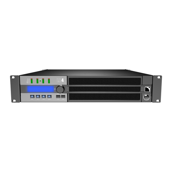
5 5 5 5 LA4 AMPLIFIED CONTROLLER LA4 AMPLIFIED CONTROLLER LA4 AMPLIFIED CONTROLLER LA4 AMPLIFIED CONTROLLER Front and rear panels Figure 3: LA4 amplified controller front & rear panels On/Off Switch XLR Input Link connector Anti-Dust Cover XLR Input connector... -
Page 14: Main Features
Simplified block diagram The LA4 combines in a 2U lightweight chassis the resources of a 2 IN / 4 OUT DSP engine driving four channels of amplification, a flash memory for preset storage and management, a front panel user interface, a Fast Ethernet device for network remote control, high performance A/D-D/A converters for audio signals, and an optional digital audio card (this option will be available as a future development). -
Page 15: A/D Converters
5 band EQ Figure 5: DSP Architecture 5.2.3 A/D Converters The LA4 amplified controller is fitted with two cascaded 24 bit A/D converters with a sampling rate of 96 kHz allowing a ground-breaking encoding dynamic of 130 dB. 5.2.4 Amplifier section The LA4 amplifier section uses a Class H technology supporting the wide dynamic range encountered in live audio productions. -
Page 16: User Interface
The L-DGA card is also for cascading several LA4 (and LA8) using the same type of cable as for the L-NET remote control network. The signal routing on the digital audio bus into any LA controller can be operated from the LA NETWORK MANAGER software. -
Page 17: Installation
Mounting The LA4 is two rack units high (2U) that can be mounted in an EIA-standard 19’’ rack (Figure 6). Four mount points are provided on the controller front panel for rack mounting. Use four screws and washers when mounting the controller to the front rack rails. -
Page 18: Cooling
If you are unsure of the output voltage of your AC mains please consult your local electrician. VOLTAGE The following table gives the LA4 Power Supply Data in nominal use (4 , 1/8 of maximum output power [see section 6.6]): Table 1: LA4 Power supply data in nominal use... -
Page 19: On/Off Switch
Changing the plug must be done by qualified personnel only. The specific safety regulations of the country of use must be strictly applied. The plug must be approved for the specific voltage and current rating given in Table 1. The ground connection of the supplied AC power cord is a safety feature. Do not attempt to disable it by using an adaptor or by other methods. -
Page 20: Wiring
Amplified Controller Amplified Controller Amplified Controller Amplified Controller USER MANUAL USER MANUAL USER MANUAL USER MANUAL VERSION 1.3.0.32A Wiring 6.5.1 XLR input connectors Two 3 pin male XLR input connectors are provided for channel A & B respectively as well as two 3 pin female XLR input link connectors wired in parallel on channel A &... -
Page 21: Speakon ® Output Connectors
® 6.5.2 Speakon output connectors ® Four 4-point Speakon connectors, located at the back of the LA4 controller, are for loudspeaker connection and are wired as follows: Top Left: Pin 1+ Out 1+ Top Right: Pin 1+ Out 3 +... -
Page 22: L-Net Wiring
Power consumption The LA4 power requirements summarized in Table 3 (4 channels being driven at the same time) are dependent of load impedance and signal level characteristics: Table 3: LA4 Maximum Output Power versus Mains Input Power... -
Page 23: Operation
Muted and not lit when the corresponding channel is unmuted (see Figure 12). This action automatically puts the LA4 in the Mute menu page. To leave the Mute menu page click on the ESC key. -
Page 24: Input & Output Gain Control
To unlock press and hold both IN A & IN B keys simultaneously until the message ‘‘DISPLAY UNLOCKED’’ is displayed. Main Screen Once the LA4 start-up procedure has fully cycled (see section 7.4.1) the LCD will display the main screen with the following information:... - Page 25 NETWORK MANAGER - User Manual’’). 4. IP address (1 to 253) The IP address identifies the current controller within a network of multiple LA4 and/or LA8 units. IP address description and setting are detailed in the OPTION menu (section 7.3.7).
-
Page 26: User Interface Menu
Remove group parameters defined in the LA NETWORK MANAGER software (Name, Gain, Delay, and Contour EQ). OPTIONS Select the LA4 IP address, input signal source (analog or digital), delay unit, and LCD screen contrast. Provide real-time temperature and RMS output voltage for each amp channel. -
Page 27: Load Preset (User: 1 To 10, Manufacturer: 11 To 99)
This LOAD PRESET menu is for loading a preset from the 99 on board memory locations: ® 11 to 99: Allocated OEM memory locations for L-ACOUSTICS factory presets. 1 to 10: Allocated memory locations for user presets (initialized from a factory preset). -
Page 28: Store Preset (User Memories 1 To 10)
PA_A PA_A PA_B PA_B Figure 18: Storing a preset ® Note: Modifying the name of a preset does not reset its basic characteristics, in particular the L-ACOUSTICS factory locked parameters. w w w . l - a c o u s t i c s . c o m... -
Page 29: Delete Preset (User Memories 1 To 10)
7.3.4 DELETE PRESET (User memories 1 to 10) The DELETE PRESET menu is for erasing a user preset previously saved in one of the 10 available user memory locations. To erase a user preset, select the DELETE PRESET menu and follow this procedure (see also Figure 19): 1. -
Page 30: Preset Parameters
Input or Output channel. ® Depending on the selected factory preset some parameters might be locked by L-ACOUSTICS . In that case the LCD displays a cross (X) instead of a value. -
Page 31: Clear Group Parameters
Therefore, when getting a unit for a standalone application that has been previously used within a network, ® L-ACOUSTICS recommends using the CLEAR GROUP PARAMETERS function in order to clear all group parameters as they cannot be seen and accessed via the front panel user interface. -
Page 32: Options
OPTIONS The OPTIONS menu is for setting the LA4 IP address, input signal source (analog or digital), delay unit, and LCD screen contrast. It also gives real-time display of each amp channel temperature and RMS output voltage as well as displaying data like MAC ADDRESS, firmware version, and onboard preset library version. - Page 33 NETWORK ADDRESS menu page It is possible to connect up to 253 LA4 or LA8 amplified controllers in multiple network topologies via the proprietary L-NET network. Each controller has to be identified within the network by its IP address (see notes below) typically of the format 192.168.1.
- Page 34 The FIRMWARE VERS menu page displays the version of the firmware in use. As an example Figure 23 indicates the 1.3.0.32 firmware version. ® Note: Check the L-ACOUSTICS web site @ www.l-acoustics.com on a regular basis for the latest firmware version and apply the instructions given in the ‘‘FIRMWARE_UPDATE_PROCEDURE.pdf’’...
-
Page 35: On Screen Messages
When switched on, the controller goes through a start-up sequence coming with the 5 following messages: DISPLAY TEST/INIT Testing sequence with all green LED momentarily lit. L-ACOUSTICS LA4 Controller type and preset library version display. PRESET VERSION 2.0 L-ACOUSTICS LA4 Firmware version display. -
Page 36: Malfunctions
Amplified Controller Amplified Controller Amplified Controller Amplified Controller USER MANUAL USER MANUAL USER MANUAL USER MANUAL VERSION 1.3.0.32A 7.4.4 Malfunctions Malfunctions not leading to controller stop: HIGH TEMPERATURE : Temperature of one of the 4 amp channel heat sinks reaching 85 °C. Input signals SIGNAL ATTENUATION going into all amp channels attenuated (see section 7.6.1). -
Page 37: Led Display
LED display 7.5.1 Output signal display Four bargraph displays are located on the front panel above the LCD screen (see Figure 24). By default they monitor the state of each of the 4 amplifier output channels via 6 different LED (LOAD, SIGNAL, -25dB, -10dB, -5dB, CLIP). Figure 24: The four bargraph displays LOAD LED The green LOAD LED is lit when a speaker is connected at the corresponding amplifier channel output and when the... -
Page 38: Routing And Input Signal Display
Amplified Controller Amplified Controller Amplified Controller Amplified Controller USER MANUAL USER MANUAL USER MANUAL USER MANUAL VERSION 1.3.0.32A 7.5.3 Routing and input signal display The four bargraph displays can also provide information about the signal routing between input and output channels for the current preset and about the input signal level. -
Page 39: Amplified Controller Protection Systems
Mains supply Under & Over-voltage Detection The LA4 amplified controller uses an auto-sensing SMPS for mains input voltages 120/230 V, 50-60 Hz (100 V version exists for Japan). The mains supply voltage is monitored at all times for under & over-voltage: the auto-sensing SMPS will automatically switch off if the mains supply voltage leaves the nominal voltage window. -
Page 40: L-Drive: Transducer Protection System
Amplified Controller Amplified Controller Amplified Controller Amplified Controller USER MANUAL USER MANUAL USER MANUAL USER MANUAL VERSION 1.3.0.32A L-DRIVE: transducer protection system The new L-DRIVE protection provides a dual analysis of both signal intensity and voltage in real time and RMS. Under extreme condition, when component membranes reach the over-excursion zone or if the coil ensemble temperature reaches a critical point, L-DRIVE is activated and acts as a power regulator. -
Page 41: Care And Maintenance
IMPORTANT Filter cleaning The air intake on the LA4 front face is fitted with a removable filter system. If the filter becomes clogged the unit will not cool as efficiently as it should, resulting in reduced output power level performances. -
Page 42: Troubleshooting
VERSION 1.3.0.32A Foam filter Front frame Figure 28: LA4 filter assembly Troubleshooting This section provides flowcharts to assist the user in troubleshooting problems with the LA4 amplified controller. The keys for interpretation of the flowcharts are the following: Symptom Remedy Comment Question Note: The flowcharts cannot cover every possible scenario the user may encounter. -
Page 43: No Power, No Sound, Or Sound Level Too Low
8.3.1 No power, no sound, or sound level too low No power, no sound, or sound level too low Check if AC outlet works, connect the AC plug, switch the power on. Reboot the controller by switching it off and on again to cancel the Standby Mode Power LCD screen... -
Page 44: Poor Sound Quality
Amplified Controller Amplified Controller Amplified Controller Amplified Controller USER MANUAL USER MANUAL USER MANUAL USER MANUAL VERSION 1.3.0.32A 8.3.2 Poor sound quality 8.3.3 Overheating Pour sound Overheating quality Clean or replace filter Controller’s Filter clogged? Set output and/or input gain (see section 8.2) output channels lower values *... -
Page 45: Specifications
9 9 9 9 SPECIFICATIONS SPECIFICATIONS SPECIFICATIONS SPECIFICATIONS Output power EIA (1 % THD, 1 kHz, all channels driven) 4 x 800 W @ 8 Ω (4 x 930 W peak) / 4 x 1000 W @ 4 Ω (4 x 1600 W peak) Max output voltage 125 V (Peak voltage, no load ) Bipolar, Class H 2-step high efficiency circuit... - Page 46 w w w . l - a c o u s t i c s . c o m...
- Page 47 w w w . l - a c o u s t i c s . c o m...
- Page 48 Document Reference: LA4_UM_EN_1.3.0.32a _________________ ® © Copyright 2009 by L-ACOUSTICS Parc de la Fontaine de Jouvence, 91462 Marcoussis cedex, France _________________ Distribution date: August 26 , 2009 w w w . l - a c o u s t i c s . c o m...
Need help?
Do you have a question about the LA4 and is the answer not in the manual?
Questions and answers