Advertisement
SERVICE MANUAL
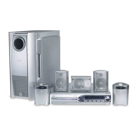
DVD DIGITAL THEATER SYSTEM
5
2004
MB192
TH-M505, TH-M501
1
PRECAUTION. . . . . . . . . . . . . . . . . . . . . . . . . . . . . . . . . . . . . . . . . . . . . . . . . . . . . . . . . . . . . . . . . . . . . . . . . 1-3
2
SPECIFIC SERVICE INSTRUCTIONS . . . . . . . . . . . . . . . . . . . . . . . . . . . . . . . . . . . . . . . . . . . . . . . . . . . . . . 1-6
3
DISASSEMBLY . . . . . . . . . . . . . . . . . . . . . . . . . . . . . . . . . . . . . . . . . . . . . . . . . . . . . . . . . . . . . . . . . . . . . . . 1-7
4
ADJUSTMENT . . . . . . . . . . . . . . . . . . . . . . . . . . . . . . . . . . . . . . . . . . . . . . . . . . . . . . . . . . . . . . . . . . . . . . . 1-32
5
TROUBLESHOOTING . . . . . . . . . . . . . . . . . . . . . . . . . . . . . . . . . . . . . . . . . . . . . . . . . . . . . . . . . . . . . . . . . 1-34
(SP-THM505C,
(SP-THM505F,
SP-THM303C)
SP-THM303F)
(XV-THM505, XV-THM501)
TABLE OF CONTENTS
COPYRIGHT © 2004 VICTOR COMPANY OF JAPAN, LIMITED
(SP-THM505S,
(SP-PWM505,
SP-THM303S)
SP-PWM501)
TH-M505
Area suffix
J ----------------------------- U.S.A.
C -------------------------- Canada
TH-M501
Area suffix
J ----------------------------- U.S.A.
No.MB192
2004/5
Advertisement

Related Manuals for JVC TH-M505


Summary of Contents for JVC TH-M505
-
Page 1: Table Of Contents
SERVICE MANUAL DVD DIGITAL THEATER SYSTEM MB192 2004 TH-M505, TH-M501 TH-M505 Area suffix J ----------------------------- U.S.A. C -------------------------- Canada TH-M501 Area suffix J ----------------------------- U.S.A. (SP-THM505C, (SP-THM505F, (SP-THM505S, (SP-PWM505, SP-THM303C) SP-THM303F) SP-THM303S) SP-PWM501) (XV-THM505, XV-THM501) TABLE OF CONTENTS PRECAUTION............... . . 1-3 SPECIFIC SERVICE INSTRUCTIONS . - Page 2 SPECIFICATION Center unit (XV-THM606/XV-THM603/XV-THM505/XV-THM501/ XV-THM303/XV-THM301) Audio section Total Harmonic Distortion 0.02% NOTE:This value is measured at System cord CONNECTOR for reference. Digital input *1 DIGITAL IN (DBS) (OPTICAL) : -21 dBm to -15 dBm (660 nm E30 nm) Video System NTSC Video section Horizontal Resolution...
-
Page 3: Precaution
SECTION 1 PRECAUTION Safety Precautions (1) This design of this product contains special hardware and voltmeter. many circuits and components specially for safety purpos- Move the resistor connection to each exposed metal es. For continued protection, no changes should be made part, particularly any exposed metal part having a return to the original design unless authorized in writing by the path to the chassis, and measure the AC voltage across... - Page 4 Preventing static electricity Electrostatic discharge (ESD), which occurs when static electricity stored in the body, fabric, etc. is discharged, can destroy the laser diode in the traverse unit (optical pickup). Take care to prevent this when performing repairs. 1.5.1 Grounding to prevent damage by static electricity Static electricity in the work area can destroy the optical pickup (laser diode) in devices such as laser products.
- Page 5 Importance administering point on the safety F901 1.6A-125V Power board Caution: For continued protection against risk of fire, replace only with same type 1.6A/125V for F901. This symbol specifies type of fast operating fuse. Precaution: Pour eviter risques de feux, remplacez le fusible de surete de F901 comme le meme type que 1.6A/125V.
-
Page 6: Specific Service Instructions
SECTION 2 SPECIFIC SERVICE INSTRUCTIONS This service manual does not describe SPECIFIC SERVICE INSTRUCTIONS. 1-6 (No.MB192) -
Page 7: Disassembly
SECTION 3 DISASSEMBLY Main body section 3.1.1 Removing the metal cover (See Figs.1 to 4) (1) From the both sides of the main body, remove the four screws A attaching the metal cover. (See Figs.1 and 2) Metal cover (2) From the back side of the main body, remove the three screws B attaching the metal cover. - Page 8 3.1.2 Removing the front panel assembly (See Figs.5 and 6) • Prior to performing the following procedures, remove the metal cover. Main board CN456 CN457 CN450 CN460 (1) From the top side of the main body, disconnect the parallel wires from the connectors (CN456, CN457) on the main board.
- Page 9 3.1.3 Removing the DVD changer mechanism assembly (See Fig.7) • Prior to performing the following procedures, remove metal cover and front panel assembly. DVD changer mechanism assembly (1) From the top side of the main body, disconnect the card CN402 CN401 CN403 wires from the connectors (CN401...
- Page 10 3.1.5 Removing the audio & digital input board (See Figs.9 and 10) • Prior to performing the following procedures, remove the metal cover. Main board CN412 Power supply board (1) From the top side of the main body, disconnect the card wires from the connectors (CN411, CN412) on the main Card wires CN411...
- Page 11 3.1.8 Removing the main board (See Fig.11) • Prior to performing the following procedures, remove the metal cover, rear panel, audio & digital input board and tuner. CN460 CN456 (1) From the top side of the main body, disconnect the card Earth wire CN457 CN401...
- Page 12 Front panel assembly section • Prior to performing the following procedures, remove the metal cover and front panel assembly. 3.2.1 Removing the phone jack board (See Fig.1) (1) From the inside of the front panel assembly, remove the screw A and screw A' attaching the phone jack board. Operation board Front panel assembly Reference:...
- Page 13 3.2.5 Removing the power key board (See Fig.4) (1) From the inside of the front panel assembly, remove the two screws E attaching the power key board. Solder poitn g Projection f Reference: Front panel assembly Parallel wire When attaching the power key board, align the projec- tions f of the front panel assembly to the holes of the power key board.
- Page 14 DVD changer mechanism assembly section • Prior to performing the following procedures, remove the metal cover, front panel assembly and the DVD changer mechanism assembly. 3.3.1 Removing the tray assemblies (See Figs.1 to 5) (1) Remove the two screws A from the top cover and release the two joints a on the both sides of the DVD changer Open det lever mechanism assembly.
- Page 15 3.3.2 Removing the DVD servo board (See Figs.6 to 8) • Prior to performing the following procedures, remove the tray Short circuit points d assemblies. (1) From the topside of the DVD changer mechanism assem- bly, solder the short-circuit points d on the DVD pick up. DVD pickup (See Fig.6) Caution:...
- Page 16 3.3.4 Removing the motor board (See Figs.9 and 10) (1) From the top side of the DVD chnager mechanism assem- bly, remove the two belts from the motor pulleys. (See Fig.9) Caution: Take care not to attach grease on the belt. Belt Belt (2) Remove the four screws D attaching the motors to the...
- Page 17 3.3.7 Removing the DVD pickup (See Figs.12 to 14) • Prior to performing the following procedures, remove the tray Short circuit points i assemblies and DVD traverse mechanism assembly. (1) From the topside of the DVD traverse mechanism assem- DVD traverse mechanism assembly bly, solder the short-circuit points i on the DVD pick up.
- Page 18 3.3.9 Removing the spindle motor board (See Figs.15 and 16) • Prior to performing the following procedures, remove the tray Motor base assemblies and DVD traverse mechanism assembly. Card wire (1) From the topside of the DVD traverse mechanism assem- Spindle motor board bly, remove the four screws K attaching the DVD traverse mechanism assembly to the DVD traverse mechanism...
- Page 19 3.3.11 Removing the side (L) assembly and tray switch board (See Figs.19 to 23) • Prior to performing the following procedures, remove the tray Joint tab r assemblies. (1) From the topside of the DVD changer mechanism assem- bly, remove the two screws R attaching the side (L) assem- Side (L) assembly bly.
- Page 20 3.3.12 Removing the side (R) assembly (See Fig.22 to 26) • Prior to performing the following procedures, remove the tray Elevator spring assemblies and DVD servo board. Hook u • When removing the DVD servo board, it is not necessary to re- move the DVD servo board from the bracket.
- Page 21 3.3.13 Removing the lifter assembly (See Figs.27 to 31) • Prior to performing the following procedures, remove the tray Hook assembies, DVD servo board, side (L) assembly and side (R) assembly. • When removing the DVD servo board, it is not necessary to re- Joint aa move the DVD servo board from the bracket.
- Page 22 3.3.14 Removing the rack holder assembly and sensor assembly (See Figs.32 to 38) • Prior to performing the following procedures, remove the tray assemblies, side (L) assembly, side (R) assembly and lifter as- Rack holder assembly sembly. Reference: If the slide gear of the DVD changer mechanism assembly places at joint ac of the rack holder assembly, turn the gear 1 counterclockwise to move the slide gear in the direction of the Gear 1...
- Page 23 Notch ag Sensor assembly Boss af Sensor assembly Sensor slider Joint ae Hole ah Slide gear Boss af Notch ag Joint ae Sensor spring Notch am Fig.35 Pin ak Slot aj Hole ah Slide lever Sensor spring Fig.38 Sensor slider Boss af Sensor spring Fig.36...
- Page 24 3.3.15 Taking out the disc in the play mode (See Fig.39 to 42) Reference: Tray assembly Disc Refer to "Removing the tray assemblies". (1) From the topside of the DVD changer mechanism assem- bly, remove the top cover. (2) Unlock the tray assemblies and draw out the tray assem- blies toward the front.
- Page 25 Speaker section 3.4.1 Removing the amplifier assembly (See Figs.1 to 3) (1) From the back side of the speaker main body, remove three screws A attaching the amplifier assembly. (See Fig.1) (2) From the bottom side of the speaker main body, remove the eight screws B attaching amplifier assembly.
- Page 26 3.4.4 Removing the heat sink bracket (See Fig.5) • Prior to performing the following procedure, remove the ampli- fier assembly. Barrier (1) From the top side of the amplifier assembly, remove the three screws G and three screws H attaching the heat sink bracket.
- Page 27 3.4.6 Removing the power board (See Figs.7 to 9) • Prior to performing the following procedures, remove the am- Barrier plifier assembly, rear panel, heat sink bracket and amplifier board. (1) From the right side of the amplifier assembly, remove the five screws J attaching the power board.
- Page 28 3.4.7 Removing the heat sink (See Figs.10 and 11) • Prior to performing the following procedures, remove the am- plifier assembly, rear panel, heat sink bracket, amplifier board and power board. (1) From right side of the amplifier assembly, remove the three screws L and three screws M attaching the heat sink.
- Page 29 3.4.9 Removing the LED board (See Fig.13) • Prior to performing the following procedures, remove the am- plifier assembly and rear panel. (1) From the top side of the amplifier assembly, disconnect the wire from the connector CN501 on the LED board. (2) Remove the two screws S attaching the LED board, take out the LED board.
- Page 30 3.4.11 Removing the speaker net (See Figs.15 and 16) (1) From right side of the speaker main body, remove the four screws U attaching the speaker net. (See Fig.15) (2) From bottom side of the speaker main body, insert the tip of the flat-bladed screwdriver or similar tool into the space between the speaker main body and speaker net, and lift the speaker net little by little to remove.
- Page 31 3.4.12 Removing the speaker (See Figs.17 and 18) • Prior to performing the following procedures, remove the speaker net. (1) From right side of the speaker main body, remove the eight screws R attaching the speaker. (See Fig.17) (2) Take out the speaker from the speaker main body. (See Fig.18) (3) Disconnect the wires from the terminal of the speaker.
-
Page 32: Adjustment
SECTION 4 ADJUSTMENT Test mode setting method (1) Unplug the power plug. (2) Insert power plug into outlet while pressing both "PLAY" key and "STANDBY/ON" key of the main body. "Area code" is indicated at the upper left of display, (3) To release test mode, press "STANDBY/ON"... - Page 33 Normal initialization method Please initialize according to the following procedures in the following case: • Just after you upgrade the firmware. • After you confirm the symptoms that a customer points out. First Initialize, and then confirm whether the symptoms are improved or not.
-
Page 34: Troubleshooting
SECTION 5 TROUBLESHOOTING This service manual does not describe SPECIFIC SERVICE INSTRUCTIONS. 1-34 (No.MB192) - Page 35 (No.MB192)1-35...
- Page 36 VICTOR COMPANY OF JAPAN, LIMITED AV & MULTIMEDIA COMPANY AUDIO/VIDEO SYSTEMS CATEGORY 10-1,1chome,Ohwatari-machi,Maebashi-city,371-8543,Japan (No.MB192) Printed in Japan...
Need help?
Do you have a question about the TH-M505 and is the answer not in the manual?
Questions and answers