Advertisement
Quick Links
Contents:
-
1
Warnings
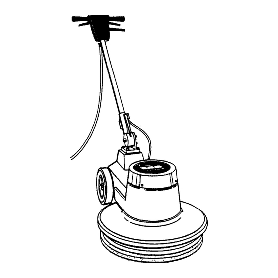
Product Description
2
Operation / Maintenance / Service
4
Wiring Diagrams
5
Motor, Frame, Driver Assembly
6
Cover Assembly
7
Handle Assembly
9
Trouble Shooting
10 Warranty
Record model and serial number located on
data label. Refer to these numbers when calling
:
MODEL
SERIAL NO. :
:
PURCHASE DATE
98116
WARNING OF
POTENTIAL INJURY:
This product contains moving parts. To
reduce the risk of injury unplug the
machine before servicing.
Whenever repairs are made ensure electrical
connections are correct and wiring matches
APPROPRIATE diagram before plugging
machine into an electrical outlet.
CAUTION:
See the Owner's Guide for
1 .)
complete operating instructions.
Maintenance and repairs must only
2.)
be done by qualified personnel.
Using non-Windsor parts to repair
3.)
this machine will void the warranty.
0 80110 USA 303-762-1800*FAX3
Advertisement

Related Manuals for Windsor L175


Summary of Contents for Windsor L175
- Page 1 Contents: Warnings Product Description Operation / Maintenance / Service Wiring Diagrams Motor, Frame, Driver Assembly Cover Assembly Handle Assembly Trouble Shooting 10 Warranty WARNING OF POTENTIAL INJURY: This product contains moving parts. To reduce the risk of injury unplug the machine before servicing.
-
Page 2: Grounding Instructions
OPERATION INSPECTION Please carefully unpack and inspect your machine U s e CAUTION: For indoor Only. for shipping damage. Each unit is operated and thor- oughly inspected before shipment, and any damage is To prevent possible damage to the floor the responsibility of the delivering carrier who should when using the Brush optlon, use water or other be notified immediately. -
Page 3: Daily Maintenance
MAINTENANCE: (At the end of each day): MAINTENANCE INSTRUCTIONS FOR THE Inspect power cord for wear. prevent electrical L175 SERIES OF FLOOR SCRUBBERS shock replace cords with frayed or cracked insulation immediately. WARNING: Remove machine power cord from electrical Place machine in the storage position. - Page 4 SWITCH CIRCUIT BREAKER POWER INDICATOR LAMP 230V & 250V WIRING DIAGRAM SWITCH CIRCUIT BREAKER SWITCH CAPACITOR...
- Page 5 Gearbox 87067 Washer, 5/16 Star 53 180 Motor, 220-24OV w/o Gearbox screw, 5/16-18 73391 Stator 70083 L175-17 73393 s t a t o r krm, 14561 87013 Washer, 114 ID x 70354 Screw. 1/4-28 x 7.50 HHCS Shield 20070 Plate, M o t o r Access...
- Page 6 Star 87083 Washer, 5/16 Split Lock 70020 screw. 1/4-20 7007 1 Screw, 4.40 PHST 38153 Handle 14603 Bumper, L175 Handle Bracket Label, 175 Lightning 14532 Bracket, Handle Pivot 27338 Motor Cover 70177 Screw, 10-32 FHMS 70086 PHMS Clamp, Cord 57028...
- Page 7 230V 250V Switch Terminal Block Asm...
- Page 8 PART DESCRIPTION QTY. NOTES Breaker 15A 25OVAC 50VDC 14700 Breaker, 7A Circuit 143 12 27558 Collar, C i t Breaker Label, Circuit Breaker Nut, 3/8-27 Panel 1/4-20 70384 Nut, 1/4-20 Hex Pltd 41234 Housing, POL Handle (Logo) Housing, POL Handle Rear Mach’d ”I”...
- Page 9 TROUBLE SHOOTING CHART CAUSE PROBLEM POSSIBLE SOLUTION power Dead electrical circuit Check building circuit machine breaker or fuse box. Power switch failure Test switch for continuity and replace if necessary. Faulty circuit breaker Replace. Faulty power cord Replace. Electrical shock Equipment not grounding Follow grounding instructions exactly.
Need help?
Do you have a question about the L175 and is the answer not in the manual?
Questions and answers