Sign In
Upload
Download
Table of Contents
Contents
Add to my manuals
Delete from my manuals
Share
URL of this page:
HTML Link:
Bookmark this page
Add
Manual will be automatically added to "My Manuals"
Print this page
×
Bookmark added
×
Added to my manuals
Manuals
Brands
Canon Manuals
Digital Camera
Ixy Digital 90
Service manual
Canon Ixy Digital 90 Service Manual
Canon digital cameras service manual
Hide thumbs
1
2
3
4
5
6
7
8
9
10
11
12
13
14
15
16
17
18
19
20
21
22
23
24
25
26
27
28
29
30
31
32
33
34
35
36
37
38
39
40
41
42
43
44
45
46
47
48
49
50
51
52
53
54
55
56
57
58
59
60
61
62
63
64
65
66
67
68
69
70
71
72
73
74
75
76
77
78
79
80
81
82
83
84
85
86
87
88
89
90
91
92
93
94
95
96
97
98
99
100
101
102
103
104
105
106
107
108
109
110
111
112
113
114
115
116
117
118
119
120
121
122
123
124
125
126
127
128
129
130
131
132
133
134
135
136
137
138
139
140
141
142
143
144
145
146
147
148
149
150
151
152
153
154
155
156
157
158
159
160
161
162
163
164
165
166
page
of
166
Go
/
166
Contents
Table of Contents
Troubleshooting
Bookmarks
Table of Contents
Table of Contents
Safety Precautions
1 Overview
Summary of Main Features
Comparison of Main Features
Ixy Digital
2 Exterior
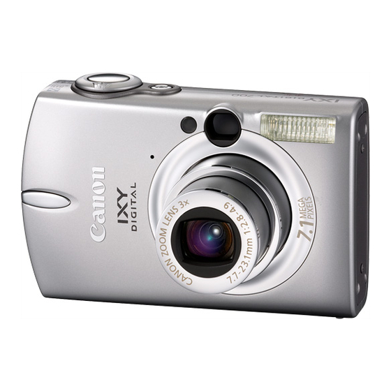
Exterior Photos
6-View Diagram
Nomenclature
3 Specifications
Product Specifications
Approx. 230,000 Pixels
Large and Fine
System Diagram
System Map
Shooting/Setting Features List
FE Lock
Direct Print
Playback Compatibility
List of Accessory and Its Compatibility
4 Accessory Specifications
Waterproof Case
Main Unchanged Accessories
Technical Description
Table of Contents
1 Functions of each Unit
Main P.C.b. Ass'y
Flash Unit
Operation Ass'y
2 Troubleshooting
When an Error Code Is Displayed
When a Problem Occurs
Simplified Troubleshooting
If the Power Cannot be Turned on
If the Flash Does Not Work
If the LCD Display Is Abnormal
3 Fuse
List of Fuses Used
Positions of Fuses Used
Section 3
1 Before Starting the Repair Work
Precautions on Flash High Voltage Circuit
List of Tools
List of Supplies
Connectors for FPC Board
2 Disassembling / Reassembling
Procedure
Disassembly of BATTERY COVER/DC COVER
Disassembly of REAR COVER UNIT/SIDE COVER
Disassembly of CROSS KEY UNIT/ANALOG KEY
Disassembly of FRONT COVER UNIT
Disassembly of LCD UNIT
Disassembly of TOP BASE UNIT
Disassembly of OPERATION FPC ASS'Y
Disassembly of MAIN PCB
Separation of FLASH UNIT/OPTICAL UNIT
Disassembly of MAIN CHASSIS UNIT
Disassembly of OPTICAL UNIT
Disassembly of BARRIER COVER
List of Screws
Section 4
1 Before Starting the Repair Work
Precautions on Flash High Voltage Circuit
List of Tools
List of Supplies
Connectors for FPC Board
2 Disassembling / Reassembling
Procedure
Separation of REAR COVER UNIT/SIDE COVER
Separation of CENTER COVER UNIT/FRONT COVER UNIT
Disassembly of BATTERY COVER/DC COVER
Separation of LCD UNIT
Separation of TOP BASE UNIT
Separation of OPERATION FPC ASS'Y
Separation of FLASH UNIT
Disassembly of MAIN PCB
Separation of FINDER UNIT
Separation of OPTICAL UNIT
Disassembly of MAIN CHASSIS UNIT
Disassembly of OPTICAL UNIT
Disassembly of BARRIER COVER
List of Screws
Recording
1 Replacement Parts and Adjustment Items
Interface
2 Adjustment Tools
3 Before Starting Electrical Adjustments
TWAIN Driver Installation
Canon DCP Connect Installation
Adjustment Software Installation
Preparation
Power Source
Interface
Starting up the Adjustment Software
Menu Window
Others
How to Use the Adjustment Software
4 Calibration
Interface
Power Source
Power Source
Focus
Interface
Power Source
5 Adjustment Procedure
Optical Unit Adjustment
Power Source
Interface
Power Source
CCD Adjustment
Power Source
Interface
Power Source
Shading Adjustment
Interface
Power Source
Imaging Process Adjustment
Power Source
Power Source
Interface
Power Source
Color Adjustment
Interface
Power Source
Pixel Dot Adjustment
Power Source
Interface
LCD Adjustment
Interface
Power Source
Flash Adjustment
Recording
Checking of Sound Recording/Output
Ixy Digital
1 Interconnection Diagram
IXY DIGITAL 90 / DIGITAL IXUS 75 / Powershot SD750 DIGITAL ELPH
IXY DIGITAL 10 / DIGITAL IXUS 70 / Powershot SD1000 DIGITAL ELPH
2 Diagrams
MAIN PCB ASS'Y (IXY DIGITAL 90 / DIGITAL IXUS 75 / Powershot SD750)
(Primary Side)
MAIN PCB ASS'Y (IXY DIGITAL 90 / DIGITAL IXUS 75 / Powershot SD750)
(Secondary Side)
ST FPC ASS'Y (IXY DIGITAL 90 / DIGITAL IXUS 75 / Powershot SD750)
(Primary Side)
ST FPC ASS'Y (IXY DIGITAL 90 / DIGITAL IXUS 75 / Powershot SD750)
(Secondary Side)
OPERATION FPC ASS'Y (IXY DIGITAL 90 / DIGITAL IXUS 75 / Powershot SD750)
(Primary Side)
OPERATION FPC ASS'Y (IXY DIGITAL 90 / DIGITAL IXUS 75 / Powershot SD750)
(Secondary Side)
BATTERY FPC ASS'Y (IXY DIGITAL 90 / DIGITAL IXUS 75 / Powershot SD750)
(Primary Side)
BATTERY FPC ASS'Y (IXY DIGITAL 90 / DIGITAL IXUS 75 / Powershot SD750)
(Secondary Side)
MAIN PCB ASS'Y (IXY DIGITAL 10 / DIGITAL IXUS 70 / Powershot SD1000) (Primary Side)
MAIN PCB ASS'Y (IXY DIGITAL 10 / DIGITAL IXUS 70 / Powershot SD1000) (Secondary Side)
ST FPC ASS'Y (IXY DIGITAL 10 / DIGITAL IXUS 70 / Powershot SD1000) (Primary Side)
ST FPC ASS'Y (IXY DIGITAL 10 / DIGITAL IXUS 70 / Powershot SD1000) (Secondary Side)
OPERATION FPC ASS'Y (IXY DIGITAL 10 / DIGITAL IXUS 70 / Powershot SD1000) (Primary Side)
OPERATION FPC ASS'Y (IXY DIGITAL 10 / DIGITAL IXUS 70 / Powershot SD1000) (Secondary Side)
BATTERY FPC ASS'Y (IXY DIGITAL 10 / DIGITAL IXUS 70 / Powershot SD1000) (Primary Side)
BATTERY FPC ASS'Y (IXY DIGITAL 10 / DIGITAL IXUS 70 / Powershot SD1000) (Secondary Side)
Advertisement
Quick Links
1
Summary of Main Features
2
Section 3
Download this manual
Table of
Contents
Previous
Page
Next
Page
1
2
3
4
5
Advertisement
Chapters
Table of Contents
4
Table of Contents
42
Section 3
49
Section 4
84
Recording
116
Ixy Digital
147
Table of Contents
Troubleshooting
Troubleshooting
44
Simplified Troubleshooting
46
Need help?
Do you have a question about the Ixy Digital 90 and is the answer not in the manual?
Ask a question
Questions and answers
Related Manuals for Canon Ixy Digital 90
Digital Camera Canon PowerShot SD750 Digital ELPH User Manual
(386 pages)
Digital Camera Canon Digital IXUS 70 User Manual
(379 pages)
Digital Camera CANON PowerShot SD870IS User Manual
(244 pages)
Digital Camera CANON POWERSHOT SD400 DIGITAL ELPH User Manual
(196 pages)
Film Camera Canon ELPH Instruction Manual
(196 pages)
Digital Camera CANON POWERSHOT SD750 DIGITAL ELPH User Manual
(154 pages)
Digital Camera Canon SD1200 IS User Manual
Canon digital camera user manual (136 pages)
Digital Camera Canon PowerShot A570IS - PowerShot A570 IS Digital Camera Software Starter Manual
Software starter guide for the canon digital camera solution disk version 30 (90 pages)
Printer Canon PowerShot A550 User Manual
Direct print user guide (82 pages)
Digital Camera CANON Digital ELPH User Manual
(82 pages)
Digital Camera CANON POWERSHOT SD870IS User Manual
(75 pages)
Digital Camera Canon PowerShot SD750 Digital ELPH User Manual
Canon user guide digital camera powershot sd 750 (36 pages)
Digital Camera Canon PowerShot Brochure & Specs
(22 pages)
Digital Camera Canon IXY DIGITAL Parts Catalog
(13 pages)
Camera Accessories Canon DIGITAL ELPH Instructions Manual
Camera accessory kit 4 for powershot sd630 and sd430 wireless digital elph cameras (11 pages)
Digital Camera Canon PowerShot SD1100 IS Specifications
Digital elph brochure (5 pages)
This manual is also suitable for:
Powershot sd750
Ixy digital 80
Digital ixus 75
Ixy digital 10
Digital ixus 70
Powershot sd1000 digital elph
...
Show all
Ixy digital
Powershot sd10
Digital elph
Table of Contents
Save PDF
Print
Rename the bookmark
Delete bookmark?
Delete from my manuals?
Login
Sign In
OR
Sign in with Facebook
Sign in with Google
Upload manual
Upload from disk
Upload from URL


Need help?
Do you have a question about the Ixy Digital 90 and is the answer not in the manual?
Questions and answers