Table of Contents
Advertisement
Quick Links
Advertisement
Table of Contents

Related Manuals for Samsung SRD-1680D


Summary of Contents for Samsung SRD-1680D
-
Page 1: Channel Dvr
8 CHANNEL/ 16 CHANNEL DVR User Manual SRD-1680D/880D... - Page 2 Disclaimer Samsung Techwin makes the best to verify the integrity and correctness of the contents in this document, but no formal guarantee shall be provided. Use of this document and the subsequent results shall be entirely on the user's own responsibility. Samsung Techwin reserves the right to change the contents of this document without prior notice.
-
Page 3: Important Safety Instructions
overview ImporTAnT SAfeTy InSTruCTIonS Read these operating instructions carefully before using the unit. Follow all the safety instructions listed below. Keep these operating instructions handy for future reference. Read these instructions. Keep these instructions. Heed all warnings. Follow all instructions. Do not use this apparatus near water. -
Page 4: Before Start
• SAMSUNG retains the copyright on this manual. • This manual cannot be copied without SAMSUNG’s prior written approval. • We are not liable for any or all losses to the product incurred by your use of non-standard product or violation of instructions mentioned in this manual. -
Page 5: Ethernet Port
operating Temperature The guaranteed operating temperature range of this product is 0°C ~ 40°C (32°F ~ 104°F). This product may not work properly if you run right after a long period of storage at a temperature below the guaranteed one. Prior to using a device that has been stored for a long period in low temperatures, allow the product to stand at room temperature for a period. -
Page 6: Table Of Contents
overview ConTenTS overvIeW Important Safety Instructions Before Start Contents Features Part Names and Functions (Front) Part Names and Functions (Rear) Remote Control InSTALLATIon Checking the installation environment Rack Installation Installing The HDD ConneCTIng WITh oTher devICe Connecting External Devices Connecting the Network LIve Getting Started Live Screen Configuration... - Page 7 SeArCh & pLAy Search Playback WeB vIeWer Introducing Web Viewer Connecting Web Viewer (Windows) Using Live Viewer (Windows) Controlling a Connected PTZ Camera Using Search Viewer 101 Viewer Setup 112 About 113 Connecting Web Viewer (Mac) 114 Using Live Viewer (Mac) 116 Mobile Viewer BACKup vIeWer 117 SEC Backup Viewer...
- Page 8 overview feATureS This product can compress 8-channel or 16-channel camera input into a H.264 video clip, or compress 8-channel HD-SDI input or 8-channel composite input, and record in HDD and replay the video at the same time. These DVRs also supports network connectivity, providing remote monitoring from a remote PC transferring video and audio data.
-
Page 9: Standards Approvals
Standards Approvals This equipment has been tested and found to comply with the limits for a Class A digital device, pursuant to part 15 of the FCC Rules. These limits are designed to provide reasonable protection against harmful interference when the equipment is operated in a commercial environment. -
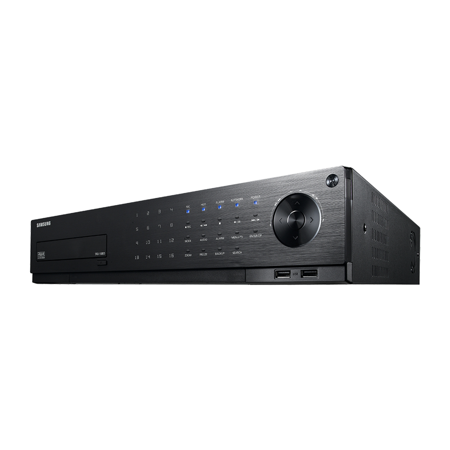
Page 10: Part Names And Functions (Front)
And funCTIonS (fronT) Srd-880d Srd-1680d Part Names Functions Channel Used to select channel numbers directly in the Live Mode, or numbers in the numeric input mode. Starts or ends the recording. Step Rewind (& ) : Used for backward frame-by-frame search while in PAUSE. - Page 11 Part Names Functions Used to turn the DVR ON/OFF. Power Functions only if the button was held for 2 seconds. USB Port 1 / 2 Connects the USB devices. Each time you press the button in Live mode, the screen mode will be switched in sequence. MODE Each time you press the button in play mode, the screen mode will be switched in sequence.
-
Page 12: Part Names And Functions (Rear)
SERIAL COM COM COM SPOT 2 eSATA NETWORK CONSOLE HDMI i h g Srd-1680d VGA OUT AUDIO OUT SPOT 1 NC NO 1 2 3 4 5 6 7 8 9 10 11 12 13 14 15 16 SERIAL COM COM COM... - Page 13 Part Names Functions - ALARM IN : Alarm Input port. SRD-880D: 1~8 CH SRD-1680D : 1~16 CH ALARM - ALARM RESET : Alarm Reset port. - ALARM OUT 1~4 : Alarm Output port. VIDEO IN Video Signal Input Port (BNC type connector).
-
Page 14: Remote Control
overview remoTe ConTroL SeArCh BACKup Displays the search menu. Displays the Backup Menu. open/CLoSe mode Opens or closes the DVD tray. Changes the screen mode. poWer Activates the DVR function. Displays the Exit pop up screen. numBer [0~ + 10] Used as the numeric input keys, or displays a single channel. - Page 15 using the numeric buttons CHANNEL 1–9 Press each button between 1 to 9. CHANNEL 10 Press the [+10] button first, then press the 0 button again within 3 seconds. CHANNEL 11–16 Press the [+10] button first, then press any number between 1 to 6 within 3 seconds. Changing the remote Control Id Remote control’s ID and DVR’s ID should be matched for proper operation.
-
Page 16: Installation
installation Please take note of the followings before using this product. • Do not use the product outdoor. • Do not spill water or liquid in the connection part of the product. • Do not impose the system to excessive shock or force. • Do not pull out the power plug forcefully. -
Page 17: Rack Installation
rACK InSTALLATIon Install the Bracket-Rack as shown in the figure, and then fasten the screws on both sides (2 screws on each side). Remove the screws on the left and right side of the DVR before installation. Fix the screws not to be loosened by vibrations. Cautions when Installing in the rack To install multiple DVRs in the rack, make sure to separate the FOOT at the bottom of each DVR. - Page 18 installation Cautions on hdd installation 1. When adding a new HDD, make sure to fasten screws tightly and use appropriate parts if required to fix the HDD. Otherwise, the product may be damaged or does not operate properly. 2. Please check the HDD compatibility before adding a HDD. Please contact your nearest dealer to obtain the list of compatible devices.
- Page 19 4. Attach the HDD onto the bracket, and fasten the screws on both sides to fix it. 5. Align the bracket with installed HDD to the guide of the case, push it toward the board. 6. You can check the HDD map directly on the DVR. Refer to “Storage device >...
-
Page 20: Connecting With Other Device
ConneCTIng exTernAL devICeS The following figures are based on Model SRD-1680D. AUDIO OUT AC 100-240V~IN AUDIO IN AUDIO IN VIDEO OUT (VGA) VGA OUT SPOT 1 AUDIO OUT NC NO 1 2 3 4 5 6 7 8... -
Page 21: Connecting Pos Device
Connecting external SATA hdd (eSATA) External SATA port is provided on the rear panel. If connected to the system, the external SATA HDD (eSATA) can be recognized and configured in “main menu > device > Storage device”. Use a cable shorter than 1 m for the external external SATA HDD (eSATA) connections. Unexpected disconnection to a device in use which is connected via eSATA may restart the system. - Page 22 Srd-1680d Sensors Alarm • ALARM IN 1 ~ 16 : Alarm Input Port • ALARM RESET : On receiving an Alarm Reset signal, the system cancels the current Alarm Input and resumes sensing. • ALARM OUT 1 ~ 4 : Alarm Output Port...
-
Page 23: Connecting The Network
Connecting the rS-485 device Connect the [Tx/rx +, –] device through the back port. system keyboard PTZ camera You can connect and control the PTZ camera which supports the RS-485 communication. Check if the RS-485 device is compatible with the product first. Pay attention not to change the polarity (+/-) of the RS-485 device when connecting it. - Page 24 connecting with other device Connecting to the network using the router Broadband Router xDSL or Cable Modem xDSL or Cable Modem NETWORK External Remote PC DDNS Server (Data Center) Connecting to network through pppoe RJ-45 Ethernet Cable (Direct Cable) PPPoE MODEM Windows NETWORK Network Viewer...
-
Page 25: Getting Started
live geTTIng STArTed Starting the system 1. Connect power cable to the product’s rear. 2. Touch and hold the front power button for over 3 seconds. It takes about 10 seconds to display the start screen after booting. 3. The boot up screen appears. Booting up may take about 3 minute, as indicates progress with icons. - Page 26 live Shutting down the System You can shut down the system only if you have logged in to the DVR. You require permission to shut down the system if you are not logged in as admin. 1. Hold the [poWer] button on the front or the remote control for over 3 seconds, or right click and click 2013-01-01 01:10:25 <Shutdown>.
-
Page 27: Locking All Buttons
The default administrator ID is “admin”, and the password must be set when the user log in at the first time. Set password for your wireless network if you use the product with a wireless router. Being not protected with password or using the default wireless router password may expose your video data to potential threat. -
Page 28: Live Screen Configuration
live LIve SCreen ConfIgurATIon Icons on the Live Screen You can check the status or operation of the DVR with the icons on the live screen. 2013-01-01 01:10:25 CAM 01 Part Names Functions Current Date, Time Displays the current time and date. Login Information When you are logged in, the “LOG ON”... - Page 29 Part Names Functions Video Input Displayed if no input is entered in the condition that the camera is set to <ON>. Status Nothing will be displayed on the screen if the camera is set to <OFF>. Camera Name/ Channel Displays the camera name and the changed channel, if any. Displayed in PTZ setting, and highlighted yellow if PTZ is in operation.
-
Page 30: Live
live Split mode menu The context sensitive menu in split mode differs, depending on the login/logout status. 2013-01-01 01:10:25 Scene Mode Spot Out 1 Spot Out 2 Audio Off Freeze Stop Alarm Record Play Search Backup Main Menu Shutdown Hide Launcher Logout... - Page 31 Single mode menu The single mode menu is available only in Single Mode. The menu, which appears as <Screen mode> on a single screen, appears as <full Screen> after selecting only one channel on a split screen. 2013-01-01 01:10:25 2013-01-01 01:10:25 Scene Mode ...
- Page 32 live Show / hide the Launcher menu The Launcher menu appears on the bottom of the live screen. 1. In Live mode, right-click to display the context menu and select <Show Launcher> or <hide Launcher>. If selected <hide Launcher>, the launcher menu disappears on the bottom of the live screen. 2.
-
Page 33: Live Mode
LIve mode SRD-1680D display Live images from 16 channels in a total of 8 layout of split screens. Switching the screen mode CH10 CH11 CH12 CH13 CH14 CH15 CH16 To switch the split mode, select a screen mode in the launcher menu, or right-click to select a screen mode in the context menu. - Page 34 CH10 CH11 CH10 CH12 CH11 CH13 CH12 CH13 CH7 CH8 CH9 CH10 CH11 CH12 CH13 CH14 CH15 CH16 CH7 CH8 CH9 CH10 CH11 CH12 CH13 CH14 CH15 CH16 live CH10 CH11 CH12 CH13 CH7 CH8 CH9 CH10 CH11 CH12 CH13 CH14 CH15 CH16 CH10 CH11 CH12...
-
Page 35: Spot Out
CH13 CH14 CH15 CH16 Switching to Single mode When in split mode, select and double-click a desired channel to switch to its Single mode. Press the number corresponding to a desired channel on the front panel or the remote control to switch to its CH10 CH13 CH14... -
Page 36: Zoom
live Zoom This is available only in Single Live mode. In Single mode, select a desired area and use the Zoom function to enlarge 2013-01-01 01:10:25 it twice. 1. Select <Zoom In> in the right-click menu. Press the [Zoom] button on the front panel or the remote control, or simply click < 2013-01-01 >... -
Page 37: Event Monitoring
evenT monITorIng This will display the channel in sync with a specific event (Sensor/Motion/Video Loss/Tampering) if it occurs. In “monitor > event display”, set the event monitoring to ON/OFF and specify the event display time. (Page 56) CH10 CH11 CH12 • If multiple events occur simultaneously, the screen will switch to a split mode. -
Page 38: Main Menu
main menu You can setup the system properties, devices, and options for recording, event, backup and network. SyStem Setup You can setup Date/Time/Language, Permission, System Properties and Log. Date/time/Language You can check and setup the current Date/Time and time related properties, as well as the language used for the interface on the screen. -
Page 39: Using The Calendar
- Time Server : Enter an IP or URL address of the time server. Date/Time/Language - Last Sync Time : Displays the most recent synchronization Date/Time/Language Holiday time from the selected time server. Time Synchronization Setup - Activate as Server : Set to <use> to allow the DVR to act ... - Page 40 main menu permission management You can set permissions of each user over the DVR's specific function and settings. Setting the Administrator You can set and change Administrator’s ID and password. The administrator can use and set all menu items and functions. Using the mouse may help make setup easier.
-
Page 41: Setting The Group
Setting the Group You can create user groups and setup permissions for those user groups. You can register a user for each group in <user>. Using the mouse may help make setup easier. 1. Use the up/down buttons (▲▼) in <System> window to move to <permission management>, and press Permission Management Group... -
Page 42: To Change The User Password
main menu to restrict the user permissions If the admin restricts all permissions of an added group, the users belonging to that group can access only the default minimum menus and can change the user’s own password only. 1. Start the DVR. If all permissions are restricted, only the Login dialog should appear. -
Page 43: Setting The User
Setting the user You can add a user and edit information of a registered user. Users can be added only if a group was created in <Group> menu. Using the mouse may help make setup easier. 1. Use the up/down buttons (▲▼) in <System> window to move to <permission management>, and press Permission Management User... -
Page 44: System Management
main menu • Manual Input of ID : Prompts you to enter the user ID manually for the login process. - Checked ( ) : Encloses the registered user IDs with the [ ] symbols. Login Use the virtual keyboard to enter the user ID. ... -
Page 45: Updating The Software
• updating the Software 1. Connect a device storing the software to be updated. (It may take about 30 seconds to recognize the device.) Upgradeable devices include USB memory, CD/DVD and network device. To update the network, the current DVR should have been connected to the network. Upgrade via the proxy server may not be enabled due to the restricted access. -
Page 46: Log Information
main menu Settings You can copy and import the DVR settings by using a storage media. Using the mouse may help make setup easier. 1. Use the up/down buttons (▲▼) in <System> window to move to <System management>, and press [eNteR] System Management Settings button. -
Page 47: Event Log
event Log Event log shows recorded events on alarms, motion detections and video loss. It also shows the log and its timestamp. Using the mouse may help make setup easier. 1. Use the up/down buttons (▲▼) in <System> window to move to <Log Information>, and press [eNteR] button. -
Page 48: Setting The Device
main menu SettING tHe DeVICe You can setup Camera, Storage Device, Remote Device, POS Device and Monitor. Camera Setting the Camera You can set Video, Audio, Channel Name and Dwell Time of a Camera. Using the mouse may help make setup easier. 1. - Page 49 • HD/SD Switch: You may setup the numbers of HD channel based on your needs, after completing setup, please click OK on HD/SD Switch menu, and DVR would restart to take effect.(HD/SD Switch is available for SRD-1680D only.) 6. When the camera setup is done, press <OK>.
-
Page 50: Setting The Ptz
You have two choices : <RS-485> and <Coaxial>. Cancel <Coaxial> type is only available for SRD-1680D SD channel. • ID : Set the ID of the connected camera of each channel. You can easily setup by using the numeric buttons on the remote control or front panel. -
Page 51: Storage Device
Storage Device You can check information on storage devices. Confirming Devices You can check storage devices and their free space, usage as well as status. Devices available are HDD, and USB devices (Memory, HDD, CD/DVD). Using the mouse may help make setup easier. 1. - Page 52 main menu Formatting You can format a storage device. Using the mouse may help make setup easier. 1. Use the up/down buttons (▲▼) in <Device> window to move to <Storage Device>, and press [eNteR] button. Storage Device Format Device HDD Alarm 2.
- Page 53 HDD Alarm You can set alarm settings for HDD defects such as Check Alarm Output Port, Replace Alarm Output Port, and its duration. Using the mouse may help make setup easier. 1. Use the up/down buttons (▲▼) in <Device> window to move to <Storage Device>, and press [eNteR] button.
- Page 54 main menu Remote Devices You can set the RS-485 communication for use of PTZ Camera and system keyboard with the DVR. Using the mouse may help make setup easier. 1. Use the up/down buttons (▲▼) in <Device> window to move to <Remote Device>, and press [eNteR] button. Remote Device 2.
- Page 55 • POS Device Setup : Sets the communication setups for the POS Device POS device and DVR. POS USE It is independent to the Remote Device setup. POS Device Setup Preset Port/Ethernet None No preset None POS Device Setup None No preset None None...
-
Page 56: Screen Setup
main menu monitor You can configure information to be displayed and its format for Spot Out monitor. Setting the monitor Using the mouse may help make setup easier. 1. Use the up/down buttons (▲▼) in <Device> window to move to <monitor>, and press [eNteR] button. Monitor Monitor Spot Out... -
Page 57: Setting The Spot Out
Setting the Spot Out You can set the DVR to output information / video apart from the monitor out. Using the mouse may help make setup easier. 1. Use the up/down buttons (▲▼) in <Device> window to Monitor move to <monitor>, and press [eNteR] button. Spot Out Monitor Mode... -
Page 58: Setting The Recording
main menu SettING tHe ReCORDING You can setup scheduled recording, event recording and other recording related settings. Recording Schedule Make your reservation on a date and time to schedule the recording on specified time. Using the mouse may help make setup easier. 1. -
Page 59: Event Record Duration
Recording Color tags Color part Names Functions White No Recording No schedule / event recording Orange Continuous Scheduled recording only Blue Event Event recording only Green Both(Cont&Evnt) Both scheduled / event recordings Each press of a selected cell will cycle through <No Recording>-<Continuous>-<event>- <Both(Cont&evnt)>. -
Page 60: Record Option
main menu Setting event Recording properties You can set each channel’s resolution, quality and FPS for event recordings. Using the mouse may help make setup easier. 1. Use the up/down buttons (▲▼) in <Record> window to move to <ReC Quality & Resolution>, and press REC Quality &... -
Page 61: Setting The Event
SettING tHe eVeNt You can set recording options when sensor, motion, image loss detection or tampering event occurs. Sensor Detection You can set the sensor’s operating condition and connected camera, as well as alarm output and its duration. Using the mouse may help make setup easier. 1. -
Page 62: Motion Detection
main menu motion Detection You can set target detection region and motion, as well as the alarm signal output. When the motion detection region is set, it detects motion within the area. Using the mouse may help make setup easier. 1. -
Page 63: Video Loss Detection
Video Loss Detection You can set the alarm to be generated on a camera disconnection, which causes a video loss. Using the mouse may help make setup easier. 1. Use the up/down buttons (▲▼) in <event> window to move to <Video Loss Detection>, and press [eNteR] Video Loss Detection button. -
Page 64: Backup
main menu Alarm Schedule You can set the conditions and operating hours for scheduled alarms. Using the mouse may help make setup easier. 1. Use the up/down buttons (▲▼) in <event> window to move to <Alarm Schedule>, and press [eNteR] button. Alarm Schedule Alarm1 2. - Page 65 If you need to install a codec in Windows, run the x264_dvr.exe file in the codec folder that is created when you back up an AVI file. - SEC : Saves data in the Samsung’s proprietary format with built-in viewer, which supports immediate playback on a PC.
-
Page 66: Network Configuration
main menu NetwORK CONFIGuRAtION It provides networked monitoring of Live screen from a remote place, and supports mail forwarding function with events. You can configure the network environment which enables such functions. Connection mode You can set the network connection route and protocol. Setting the Connection Sets the protocol and environment of the network. - Page 67 • IP Address, Gateway, Subnet Mask, and DNS Connection Mode - For <Static> : You can directly input IP Address, Gateway, Interface Port Subnet Mask and DNS. IP Type PPPoE - For <DHCp> : IP Address, Gateway, and Subnet Mask ...
- Page 68 main menu Notification In a multi-browser environment, the <HTTP Port> should be set to 80 (private port). Select one between 4505 and 4530 for RTSP • Network Overview Router (External IP: 109.112.92.133, Cable/ADSL Modem Local IP: 192.168.1.1 Internet DDNS Server (www.samsungipolis.com) DVR 1 DVR 2...
- Page 69 • 1st Set port Forwarding Setting Port Forwarding is 4520~4524 (4520, 4521, 4522, 4523, 4524) Port Forwarding is 80 SRD-1680D SRD-1680D 192. 168. 1. 200 192. 168. 1. 200 4520 4520 • 2nd Set port Forwarding Setting Port Forwarding is 4525~4529...
-
Page 70: Connecting And Setting The Network
main menu Connecting and Setting the Network Networking may differ from the connection method, check your environment before setting the connection mode. when no router is used • Static mode - Internet connection : Static PPPoE, leased line, and LAN environments allows connection between the DVR and remote user. - Page 71 when a router is used To avoid IP address conflict with the DVR's static IP, check followings : • Setting the DVR with a static Ip - Internet connection : You can connect the DVR to a router which is connected to an ADSL/Cable modem or a router in a Local Area Network (LAN) environment.
- Page 72 main menu • Setting Router’s port Forwarding 1. Set the protocol to <tCp>. Connection Mode 2. External Port Range : Enter the TCP Port set in the Port Interface <Device port> in <port> menu of the connected DVR. Protocol Type If more than one DVRs are connected to the router, the ...
-
Page 73: Ddns Setting
DDNS Site : iPOLiS • DDNS Settings of the Router Select the corresponding menu for the network transfer protocol of the router. • SettING up SAmSuNG ipOLiS DDNS Go to Your PC 1. Open your browser and go to http://www.samsungipolis.com and click <LOGIN>. - Page 74 Not Used DDNS Host Address http://www.samsungipolis.com/ Cancel 3. Under Product ID, enter the product ID you created on the DDNS Samsung iPOLiS website. Under Quick Connect, select <use> and click <OK>. DDNS Site iPOLiS Server Name www.samsungipolis.com ...
-
Page 75: Live Transfer
Live transfer Sets the quality of the image that is transferred from the DVR to the network. Using the mouse may help make setup easier. 1. Use the up/down buttons (▲▼) in <Network> window to move to <Live transfer>, and press [eNteR] button. Live Transfer The Live Transfer window appears. -
Page 76: Mailing Service
main menu mailing Service You can send an e-mail to a DVR-registered user at a specific time interval, or if an event occurs. If an event occurs with a channel where the camera’s video is set to <OFF> or the remaining recording count is set to <OFF>, only the text notification will be sent to the applicable email address. -
Page 77: Event Setting
event Setting You can set the interval and type of the event that will be sent to the user. Using the mouse may help make setup easier. 1. Use the up/down buttons (▲▼) in <Network> window to move to <mailing Service>, and press [eNteR] button. Mailing Service Event SMTP... -
Page 78: Recipient Setting
main menu Recipient Setting You can add/remove a recipient(s) to/from the specified group and edit the group if necessary. Using the mouse may help make setup easier. 1. Use the up/down buttons (▲▼) in <Network> window to move to <mailing Service>, and press [eNteR] button. Mailing Service Recipient SMTP... -
Page 79: Controlling A Ptz Device
CONtROLLING A ptZ DeVICe The DVR enables you to adjust the settings of a PTZ camera as well as an ordinary one to your preference. ptZ Device The PTZ device can be activated only if a channel in connection with the PTZ camera is selected. Getting started with ptZ The PTZ camera is available, only if a channel is selected, in the following way : Using the remote control buttons... -
Page 80: Using The Ptz Camera
For the coaxial communications, the operation may differ depending on the protocol. For the <Coaxial> type, only SRD-1680D is supported. Before entering the PTZ device control mode, set the values of the PTZ device in the <Setting the PTZ> menu. -
Page 81: Camera Setting
2013-01-01 01:10:25 The camera-specific menu appears. You can configure the settings of only those cameras that support the protocols of Samsung, Pelco D/P, AD and Panasonic. If you are setting Auto Pan or Pattern in the camera menu, press Camera Setup and hold the appropriate button for a certain time so that the button operation can be different from that in normal PTZ setting. -
Page 82: Search & Play
search & play SeARCH You can perform the search for recorded data by the time or by the search criteria such as an event. You can access the <Search> menu directly in Live mode. 1. In Live mode, right-click any area of the screen. The Live menu appears. -
Page 83: Event Search
• Zoom In : The map enlarges in detail. Time Search It will switch in the sequence of 24 hours - 16 hours - 8 hours 2013-01-01 Go to First Go to Last - 4 hours. Overlapped Data List1 Zoom In Zoom Out • Zoom Out : The map will switch in the reverse order of the 00:01... -
Page 84: Pos Search
search & play pOS Search You can search for data in the POS device that is connected to the DVR. You can use the mouse to select the related items. 1. Select <pOS Search> in the <Search> menu. POS Search 2. -
Page 85: Playback
pLAyBACK play You can play data stored in the HDD and backup a desired portion of the data. Using the mouse may help make setup easier. 1. In Live mode, click <play> in the right-click menu or 2013-01-01 01:10:25 < >... - Page 86 search & play using the playback Button Part Names Functions Play Timeline Indicates the current playback point, and can be used to move. Skip Backward Moves backward by unit time. (Move by 10 minutes) Backward Fast Used for quick backward playback. (2 - 64x speed) Play Backward Slow Used for backward frame-by-frame search while in PAUSE.
-
Page 87: Web Viewer
web viewer IntroducIng Web VIeWer What is Web Viewer? Web Viewer allows remote access to your DVRs. You have access to li ve video, archived video, PTZ control (if configured), etc. Product Features Network • Remote access from a standard browser • Supports PTZ camera controls • Supports 1, 4, 9, 16 camera viewing formats (maximum of 16 cameras in the list). -
Page 88: Connecting Web Viewer (Windows)
web viewer connectIng Web VIeWer (Windows) 1. Open your web browser and type the IP address or URL of DVR into the URL address box. “192.168.1.200” is set to IP by default. Set to an available IP address in IP Installer or "Network > Connection Mode”. - Page 89 5. When a program installation wizard window appears, press the [Install] button to install the program. 6. When the program installation is complete, the Explorer window closes. Open the web viewer window again to log in. Live Viewer's main screen appears when you log in successfully after installing the program.
-
Page 90: Using Live Viewer (Windows)
web viewer uSIng LIVe VIeWer (Windows) The Live Viewer screen consists of following : Menu Functions Menu Selection Switches into corresponding menu screen by clicking each menu. Address, Name, Time Displays the IP, model name, time, etc. of connected DVR. DVR Time, PC Time Select <DVR Time>... - Page 91 Dual Stream selection: Right click on any of live channels, there will be a drop-down menu profile1/profile2. The default setting is profile1, that's to say, video displayed as profile1 resolution. If you select profile2, Video will be displayed as profile2 resolution. profile1: Live transfer resolution, Profile 2: Recording resolution oSd Information display a The channel number of the connected DVR are displayed.
- Page 92 web viewer Split-Screen Click split mode selection button to switch to the corresponding screen mode. SINGLE MODE QUAD MODE NINE MODE SIXTEEN MODE to switch to full screen mode Click < >. Current split screen appears in full screen. Press the [eSc] key to exit the full screen mode. 92_ web viewer...
- Page 93 changing the Live Screen Mode 16-split mode does not support “Sequence”, “Previous” and “Next”. : When this button is clicked, the previous screen • appears. - In SINGLE MODE, the channel numbers are switched in reverse order. - In QUAD MODE, the screens are changed like 1st 4 channels (1~4) 2nd 4 channels (13~16) 3rd 4 channels (9~12) ...
- Page 94 web viewer to print a screen 1. Click < > button. 2. Print current camera’s video image with the printer connected to the PC operating the Web Viewer. to save as AVI 1. Click < > button. When “AVI Setup” window appears, select the record saving path and capacity.
-
Page 95: Controlling A Connected Ptz Camera
controLLIng A connected PtZ cAMerA controlling PtZ If PTZ camera is connected, the < > icon appears on screen. When selecting corresponding camera channel, the PTZ tab is provided to allow you to control the PTZ. Part Names Functions Direction Adjustment Adjusts the direction of a camera. - Page 96 web viewer to set a preset 1. Click < > button to display “Preset” window. 2. Click < > to select a desired preset number. 3. Enter the name of preset. 4. Use direction keys to adjust the direction which camera aims at.
- Page 97 controlling oSd Menu If connected PTZ camera supports the OSD menu, press the < > to enter camera’s menu screen to change its settings. Part Names Functions Direction Adjustment You can go to a desired menu. ENTER Selects a desired item. Menu On/Off You can On/Off camera’s OSD menu settings.
-
Page 98: Using Search Viewer
web viewer uSIng SeArch VIeWer The Search Viewer screen consists of following : Up to 3 users can access simultaneously. Menu Functions Menu Selection Switches to the corresponding menu screen by clicking each menu. Address, Name, Time Displays the IP, model name, time, etc. of connected DVR. Split Mode Selection Selects the type of split screen and selects the channel displayed in Display Pane. - Page 99 Menu Functions Play Control Adjusts current video’s playback speed and played time position. Displays the corresponding color depending on recorded data type if you place your Recording Color mouse cursor on that area. User ID, Logout Displays the user's ID. Click Logout icon for logout. Display Pane Plays corresponding data on the screen if you select a search result.
- Page 100 web viewer names and Functions of Play buttons a Moves backward by 10 minutes from the current playing point. b Plays in reverse at doubled speed. The playback speed is doubled up to 64x speed. c Moves backward by 1 second from current playing point. d Moves forward by 1 second from current playing point.
-
Page 101: Viewer Setup
VIeWer SetuP You can configure the DVR settings remotely on the network. To configure the DVR settings, click <Setup>. System You can configure the various settings of the DVR system. date/time/Language For more information, refer to <date/time/Language> in the <System Setup> menu. (Page 38) 1. - Page 102 web viewer holiday You can set specific dates to Holidays according to your preferences. For more information, refer to <Setting holiday> in the <System Setup> menu. (Page 39) Permission Management For more information, refer to <Permission Management> in the <System Setup> menu. (Page 40) • Admin You can change the admin ID or the password.
- Page 103 • user You can add, change or remove a user or users. • Setup You can set the user permission. System Management For more information, refer to <System Management> in the <System Setup> menu. (Page 44) • System Information You can see information of the current system. Check the Software Version, Broadcast Format and MAC Address.
- Page 104 web viewer device You can check a list of devices that are connected to the DVR and configure the necessary settings. Click <device> in the menu screen. For more information, refer to “Setting the device”. (Page 48) camera • camera You can configure the settings of the camera that is connected to the DVR.
-
Page 105: Remote Device
Storage device You can check and change the settings of the storage device. • device You will see a list of storage devices that are connected to the DVR. You can check the type, used/total, usage and status of the device. • hdd Alarm You can set the alarm output channel and the alarm duration for an error. -
Page 106: Pos Device
web viewer PoS device You can set the channel, preset and communication port of the POS device that is connected to the DVR. You cannot set to use the POS device remotely. Monitor • Monitor You can configure the monitoring screen settings and set the output system. -
Page 107: Recording Schedule
record For more information, refer to <Setting the recording>. (Page 58) recording Schedule If you set a recording schedule for a specific date and time, the recording will start at that specific time. - Apply to All CH : Click <Apply to All ch> to display the confirmation window. -
Page 108: Sensor Detection
web viewer rec Quality & resolution • Standard/event You can set the resolution, frame rate and recording quality for each channel. If HD camera is connected to the current channel, then HD option would be displayed in recording resolution. If you select HD as resolution, standard recording resolution of the channel is set as 1920 x 1080. - Page 109 Motion detection You can set the motion detection mode and the sensitivity as well as the alarm output type and the duration. • Motion region Set the target motion detection area. Video Loss detection You can set the alarm output time if a video loss occurs. tampering detection You can set whether to generate alarm and its dwell time for video tampering events.
-
Page 110: Connection Mode
web viewer Alarm Schedule You can schedule the alarm output according to the day of the week and the time. The default setting is Event Sync, which activates the alarm only if an event occurs. network For more information, refer to <network configuration>. (Page 66) connection Mode A remote user can access the DVR via the network to check the current mode and the IP address. - Page 111 ddnS You can check the DDNS settings. Live transfer Sets the quality of the image that is transferred from the DVR to the network. • Live transfer A remote user can set the image resolution of the transferred data. Mailing Service You can specify the SMTP server that sends a mail if an event occurs and set the recipient group and users.
-
Page 112: About
web viewer • group You can add a group to receive the mail if an event occurs and set the permission to receive the event mail for each group. • recipient You can add a user or users who will receive the mail. SnMP You can configure the settings for the SNMP protocol. -
Page 113: Connecting Web Viewer (Mac)
connectIng Web VIeWer (Mac) Safari on MAc. If you want to use SRD-Series DVR Web Viewer with Safari Browser on a Mac, please refer to this user guide and install Multi Viewer with firmware upgrade if necessary. • Mac OS versions available : 10.6 or later version • Silverlight : 5 or later • Safari : 5 or later 1. -
Page 114: Using Live Viewer (Mac)
web viewer • If Microsoft Silverlight plug-in is already installed 1. Use a web browser to connect to the DVR. 2. If Silverlight plug-in is already installed, you will see the login screen as shown. 3. If the login screen does not appear, check if the DVR set is connected properly with a valid IP address. - Page 115 Menu Functions Name, Address Displays a connected DVR’s IP address and model name. Audio Sets the sound connected to each channel to ON/OFF. Select < DVR Time > or < PC Time > for the OSD time information display setting of the Live DVR Tim, PC Time Viewer.
-
Page 116: Mobile Viewer
web viewer MobILe VIeWer What is Mobile Viewer? Mobile Viewer is management software that enables you to connect to DVR (Digital Video Recorder) remotely and control the video playback and PTZ operations (if configured) in real time. Key Features • Remote access via Smart phone • Voice Recognition • 1-split and 4-split modes supported in Live Viewer • Supports single channel search function... -
Page 117: Backup Viewer
backup viewer Sec bAcKuP VIeWer You can play a file that is backed up in the format of SEC. Backup in SEC format produces backup data file, library file and self-executable viewer file. If you run the backup file viewer, the backup data file will be automatically played. d e f recommended System requirements PCs with a lower specification than the recommended below may not fully support forward/backward and... - Page 118 backup viewer Part Names Functions Set the screen’s aspect ratio to be displayed. Split Screen The screen switches to the selected split screen mode. Split screen function is not supported during the CD/DVD backup. Saves the current video’s image as in an image file. Supports jpeg file format. Screen Printout Prints out the current screen.
-
Page 119: Appendix
NTSC: Up to 240fps @ 1920x1080 / PAL: Up to 200fps @ 1920x1080 NTSC: Up to 240fps @ 1280x720 / PAL: Up to 200fps @ 1280x720 y SRD-1680D Record Rate NTSC: Up to 240fps @ 1920x1080 / PAL: Up to 200fps @ 1920x1080... - Page 120 Details Item SRD-880D SRD-1680D Option 1) NTSC : 2M(240fps),1M~4CIF(480fps)/ NTSC : 1~2M(240fps) / PAL : PAL : 2M(200fps),1M~4CIF(400fps) Transmission speed 1~2M(200fps) Option 2) NTSC : 4CIF(120fps),2CIF(24 0fps),CIF(480fps)/ PAL : 4CIF(100fps),2 CIF(200fps),CIF(400fps) Bandwidth Up to 64Mbps Network (IPv4) Bandwidth control...
- Page 121 Mouse, Remote Controller y Samsung-E/Samsung-T/Pelco-D/Pelco-p/Panasonic/ Phillips/ AD/ DIAMOND/ Protocol support ERNA/ KALATEL/ VCL TP/VICON/ ELMO/GE y PTZ Control via Coaxial Cable (Samsung CCVC, Pelco-C (Coaxitron)) General Input Voltage / Current 100 to 240 VAC ±10%; 50/60 Hz, Autoranging Electrical Power consumption Max.
-
Page 122: Product Overview
appendix Product overview • Srd-880d unit : mm(inch) 122_ appendix... - Page 123 • Srd-1680d unit : mm(inch) English _123...
-
Page 124: Default Setting
The settings are made as follows; • Use System/Load Factory Default in MENU The default settings are based on SRD-1680D. The default administrator ID is “admin”, and the password must be set when the user log in at the first time. - Page 125 Category Details Factory Default Baudrate 9600 Parity None Data Remote Device Stop bit System Keyboard Remote Control ON(00) POS Device Event Display Device Display Monitor Multi CH SEQ Time 5 sec VGA/HDMI 1280X1024 Multi Spot Monitor Spot Out 1 Spot Out Spot Out 2 Event Display Live Screen...
- Page 126 appendix Category Details Factory Default Mode Sensitivity Level10(high) Motion Detection Alarm None Duration 10 sec Motion Region All Area Video Loss State Event Video Loss Detection Alarm None Duration 10 sec Mode Sensitivity Medium Tampering Detection Alarm None Duration 10 sec Alarm Schedule Alarm1 Event Sync...
-
Page 127: Troubleshooting
troubLeShootIng Symptom Countermeasures The system does not turn on and the indicator on the y Check if the power supply system is properly connected. front panel does not work at all. y Check the system for the input voltage from the power source. y If the problem persists even after you have taken the above actions, check the power supplier and replace it with a new one if neccessary. - Page 128 appendix Symptom Countermeasures I've found that the DVR does not recognize as many y It takes time for the DVR to recognize multiple external HDDs. Try again disks as installed when I have connected multiple in a moment and if the problem (of failure to recognize as many HDDs external HDDs to the DVR.
- Page 129 Symptom Countermeasures Recording does not work. y If your player does not display a Live image at all, that indicates recording does not work so first check if you see an image on the screen. y Recording does not work if the recording settings are not properly configured.
-
Page 130: Open Source Announcement
The software included in this product contains copyrighted software that is licensed under the GPL/LGPL. You may obtain the complete Corresponding Source code from us for a period of three years after our last shipment of this product by sending email to help.cctv@samsung.com If you want to obtain the complete Corresponding Source code in the physical medium such as CD-ROM, the cost of physically performing source distribution might be charged. - Page 131 c) Accompany it with the information you received as to the offer to of this License, you may choose any version ever published by the Free distribute corresponding source code. (This alternative is allowed Software Foundation. only for noncommercial distribution and only if you received the 10.
-
Page 132: Terms And Conditions
consider it more useful to permit linking proprietary applications with the computer or modifying a private copy. Propagation includes copying, library. If this is what you want to do, use the GNU Lesser General distribution (with or without modification), making available to the public, Public License instead of this License. - Page 133 4. conveying Verbatim copies. A separable portion of the object code, whose source code is excluded from the Corresponding Source as a System Library, need not be You may convey verbatim copies of the Program’s source code as you included in conveying the object code work. receive it, in any medium, provided that you conspicuously and appropriately publish on each copy an appropriate copyright notice;...
- Page 134 permits relicensing or conveying under this License, you may add to a In the following three paragraphs, a “patent license” is any express covered work material governed by the terms of that license document, agreement or commitment, however denominated, not to enforce a provided that the further restriction does not survive such relicensing or patent (such as an express permission to practice a patent or covenant conveying.
- Page 135 15. disclaimer of Warranty. Finally, software patents pose a constant threat to the existence of any free program. We wish to make sure that a company cannot effectively THERE IS NO WARRANTY FOR THE PROGRAM, TO THE EXTENT restrict the users of a free program by obtaining a restrictive license from PERMITTED BY APPLICABLE LAW.
- Page 136 You may charge a fee for the physical act of transferring a copy, and layouts and accessors, and small macros and small inline functions (ten you may at your option offer warranty protection in exchange for a fee. lines or less in length), then the use of the object file is unrestricted, regardless of whether it is legally a derivative work.
-
Page 137: Openssl License
END OF TERMS AND CONDITIONS acceptance of this License to do so, and all its terms and conditions for copying, distributing or modifying the Library or works based on it. 10. Each time you redistribute the Library (or any work based on the how to Apply these terms to Your new Libraries Library), the recipient automatically receives a license from the original licensor to copy, distribute, link with or modify the Library subject to... - Page 138 1.3. “Covered Software” means (a) the Original Software, or (b) with Netscapes SSL. This library is free for commercial and non- commercial use as long as the following conditions are aheared to. The Modifications, or (c) the combination of files containing Original Software following conditions apply to all code found in this distribution, be it the with files containing Modifications, in each case including portions RC4, RSA, lhash, DES, etc., code;...
- Page 139 b) under Patent Claims infringed by the making, using, or selling of version will be given a distinguishing version number. Except as Modifications made by that Contributor either alone and/or in provided in Section 4.3, no one other than the license steward has the combination with its Contributor Version (or portions of such right to modify this License.
- Page 140 DAMAGES, SO THIS EXCLUSION AND LIMITATION MAY NOT APPLY • You may not pretend that you wrote this software. If you use it, or TO YOU. only parts of it, in a program, you must acknowledge somewhere in your documentation that you have used the FreeType code. (`credits’) 8.
- Page 141 For more additional information, send email to help.cctv@samsung.com. THIS SOFTWARE IS PROVIDED BY THE COPYRIGHT HOLDERS AND CONTRIBUTORS “AS IS” AND ANY EXPRESS OR IMPLIED...
- Page 142 BSD 2.0 http://www.opensource.org/licenses/bsd-license.html 4. Neither the name of the University nor of the Department may be For more additional information, send email to help.cctv@samsung.com. used to endorse or promote products derived from this software copyright (c) 1998-2000 university college London without specific prior written permission.
- Page 143 Part 4: Sun Microsystems, Inc. copyright notice THIS SOFTWARE IS PROVIDED BY THE COPYRIGHT HOLDERS AND CONTRIBUTORS “AS IS” AND ANY EXPRESS OR IMPLIED (bSd) WARRANTIES, INCLUDING, BUT NOT LIMITED TO, THE IMPLIED WARRANTIES OF MERCHANTABILITY AND FITNESS FOR A Copyright ©...
- Page 144 License urL miniupnpc 1.5 BSD 2.0 http://miniupnp.free.fr/ For more additional information, send email to help.cctv@samsung.com. THIS SOFTWARE IS PROVIDED BY THE COPYRIGHT HOLDERS AND CONTRIBUTORS “AS IS” AND ANY EXPRESS OR IMPLIED copyright (c) 2005-2009, thomas bernArd WARRANTIES, INCLUDING, BUT NOT LIMITED TO, THE IMPLIED WARRANTIES OF MERCHANTABILITY AND FITNESS FOR A PARTICULAR PURPOSE ARE DISCLAIMED.
- Page 145 copyright (c) 1984-2000 carnegie Mellon university. 3. The name(s) of the authors of this software must not be used to endorse or promote products derived from this software without prior written permission. All rights reserved. THE AUTHORS OF THIS SOFTWARE DISCLAIM ALL WARRANTIES Redistribution and use in source and binary forms, with or without WITH REGARD TO THIS SOFTWARE, INCLUDING ALL IMPLIED modification, are permitted provided that the following conditions are...
- Page 146 El símbolo Eco representa el compromiso de Samsung Techwin de fabricar productos que respeten el medio ambiente e indica a la vez que este equipo cumple con la Directiva de la Unión Europea EU RoHS.
- Page 147 SAMSUNG TECHWIN AMERICA Inc. SAMSUNG TECHWIN EUROPE LTD. 100 Challenger Rd. Suite 700 Ridgefield Park, NJ 07660 Samsung House, 1000 Hillswood Drive, Hillswood Business Toll Free : +1-877-213-1222 Direct : +1-201-325-6920 Park Chertsey, Surrey, UNITED KINGDOM KT16 OPS Fax : +1-201-373-0124 TEL : +44-1932-45-5300 FAX : +44-1932-45-5325 www.samsungcctvusa.com...
Need help?
Do you have a question about the SRD-1680D and is the answer not in the manual?
Questions and answers
How do i reset, as my password does not work any longer since we had power cut issues
If you forgot the password on a Samsung SRD-1680D after a power cut, you need to contact the DVR administrator for help. The manual does not provide a password reset procedure.
This answer is automatically generated