Table of Contents
Advertisement
Advertisement
Chapters
Table of Contents

Related Manuals for Asus B85M-F


Summary of Contents for Asus B85M-F
- Page 1 B85M-F...
- Page 2 Product warranty or service will not be extended if: (1) the product is repaired, modified or altered, unless such repair, modification of alteration is authorized in writing by ASUS; or (2) the serial number of the product is defaced or missing.
-
Page 3: Table Of Contents
Contents Safety information ...................... iv About this guide ......................iv Package contents ....................... vi B85M-F specifications summary ................vi Product introduction Before you proceed ..................1-1 Motherboard overview ................. 1-1 Central Processing Unit (CPU) ..............1-3 System memory .................... 1-6 Expansion slots .................... -
Page 4: Safety Information
Safety information Electrical safety • To prevent electrical shock hazard, disconnect the power cable from the electrical outlet before relocating the system. • When adding or removing devices to or from the system, ensure that the power cables for the devices are unplugged before the signal cables are connected. If possible, disconnect all power cables from the existing system before you add a device. -
Page 5: Conventions Used In This Guide
Refer to the following sources for additional information and for product and software updates. ASUS websites The ASUS website provides updated information on ASUS hardware and software products. Refer to the ASUS contact information. Optional documentation Your product package may include optional documentation, such as warranty flyers, that may have been added by your dealer. -
Page 6: Package Contents
® * Hyper DIMM support is subject to the physical characteristics of individual CPUs. Please refer to Memory QVL for details. ** Refer to www.asus.com for the latest Memory QVL (Qualified Vendors List). ® *** Due to Intel chipset limitations, DDR3 1600MHz and higher memory modules on XMP mode will run at the maximum transfer rate of DDR3 1600MHz. - Page 7 - ASUS Fanless Design: Stylish Heatsink solution - ASUS Fan Xpert ASUS Q-Design - ASUS Q-Slot ASUS EZ DIY: - ASUS UEFI BIOS EZ Mode featuring a friendly graphical user interface - ASUS CrashFree BIOS 3 - ASUS EZ Flash 2 (continued on the next page)
- Page 8 BIOS features 64 Mb Flash ROM, UEFI AMI BIOS, PnP, DMI2.0, WfM 2.0, SM BIOS 2.7, ACPI 4.0a, Multi-language BIOS, ASUS EZ Flash 2, ASUS CrashFree BIOS 3, My Favorites, Quick Note, Last Modified Log, F12 PrintScreen, F3 Shortcut functions and ASUS DRAM SPD (Serial Presence Detect) memory...
-
Page 9: Product Introduction
The edge with external ports goes to the rear part of the chassis as indicated in the image below. 1.2.2 Screw holes Place six screws into the holes indicated by circles to secure the motherboard to the chassis. Do not overtighten the screws! Doing so can damage the motherboard. ASUS B85M-F... -
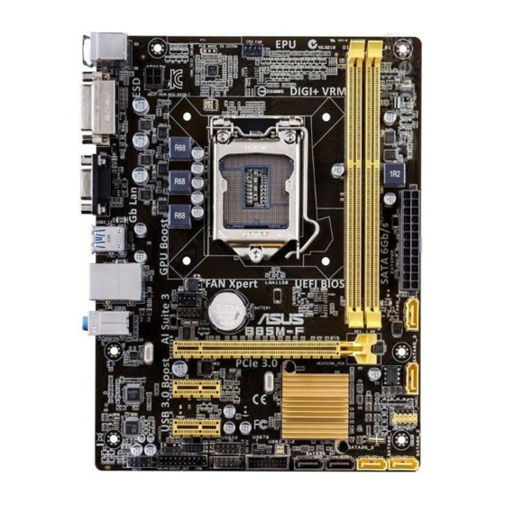
Page 10: Motherboard Layout
Place this side towards the rear of the chassis B85M-F 1.2.3 Motherboard layout 17.5cm(6.9in) CPU_FAN KBMS DIGI +VRM ATX12V USB3_12 LAN_USB34 CHA_FAN BATTERY AUDIO B85M-F PCIEX16 8111GR 64Mb BIOS PCIEX1_1 Super Intel ® SPEAKER F_PANEL PCIEX1_2 USB56 USB78 CLRTC USB3_910... -
Page 11: Central Processing Unit (Cpu)
Contact your retailer immediately if the PnP cap is missing, or if you see any damage to the PnP cap/socket contacts/motherboard components. ASUS will shoulder the cost of repair only if the damage is shipment/ transit-related. -
Page 12: Installing The Cpu
1.3.1 Installing the CPU Chapter 1: Product introduction... -
Page 13: Cpu Heatsink And Fan Assembly Installation
1.3.2 CPU heatsink and fan assembly installation Apply the Thermal Interface Material to the CPU heatsink and CPU before you install the heatsink and fan if necessary. To install the CPU heatsink and fan assembly ASUS B85M-F... -
Page 14: System Memory
CPU spec, DIMM voltage below 1.65V is recommended to protect the ® CPU. Channel Sockets Channel A DIMM_A1 Channel B DIMM_B1 B85M-F B85M-F 240-pin DDR3 DIMM sockets 1.4.2 Memory configurations You may install 1GB, 2GB, 4GB, and 8GB unbuffered non-ECC DDR3 DIMMs into the DIMM sockets. Chapter 1: Product introduction... -
Page 15: Installing A Dimm
• The maximum 16GB memory capacity can be supported with 8GB or above DIMMs. ASUS will update the memory QVL once the DIMMs are available in the market. • The default memory operation frequency is dependent on its Serial Presence Detect (SPD), which is the standard way of accessing information from a memory module. -
Page 16: Expansion Slots
To remove a DIMM Expansion slots In the future, you may need to install expansion cards. The following sub-sections describe the slots and the expansion cards that they support. Unplug the power cord before adding or removing expansion cards. Failure to do so may cause you physical injury and damage motherboard components. -
Page 17: Installing An Expansion Card
This motherboard supports one PCI Express x16 graphics card that complies with the PCI Express specifications. IRQ assignments for this motherboard shared PCIE x16 shared PCIE x1_1 shared PCIE x1_2 shared Intel PCH SATA Controller shared HD Audio shared USB2.0_1 shared USB2.0_2 shared USB3.0 shared ASUS B85M-F... -
Page 18: Jumpers
B85M-F Normal Clear RTC (Default) B85M-F Clear RTC RAM To erase the RTC RAM: Turn OFF the computer and unplug the power cord. Use a metal object such as a screwdriver to short the two pins. Plug the power cord and turn ON the computer. -
Page 19: Connectors
8-channel configurations, the function of this port becomes Front Speaker Out. Microphone port (pink). This port connects a microphone. To configure an 8-channel audio output: Use a chassis with HD audio module in the front panel to support an 8-channel audio output. ASUS B85M-F 1-11... - Page 20 Audio 2.1, 4.1, 5.1 or 7.1-channel configuration Headset Port 4.1-channel 5.1-channel 7.1-channel 2.1-channel Light Blue Line In Rear Speaker Out Rear Speaker Out Rear Speaker Out (Rear panel) Lime (Rear panel) Line Out Front Speaker Out Front Speaker Out Front Speaker Out Pink (Rear panel) Mic In Mic In...
-
Page 21: Digital Audio Connector (4-1 Pin Spdif_Out)
B85M-F HD-audio-compliant Legacy ACʼ97 pin definition compliant definition B85M-F Front panel audio connector • We recommend that you connect a high-definition front panel audio module to this connector to avail of the motherboard’s high-definition audio capability. • If you want to connect a high-definition front panel audio module to this connector, set the Front Panel Type item in the BIOS setup to [HD]. -
Page 22: Cpu And Chassis Fan Connectors (4-Pin Cpu_Fan, 4-Pin Cha_Fan)
The CPU_FAN connector supports a CPU fan of maximum 1A (12 W) fan power. Only the 4-pin CPU fan support the ASUS Fan Xpert feature. USB 2.0 connectors (10-1 pin USB78, USB56) These connectors are for USB 2.0 ports. Connect the USB module cable to any of these connectors, then install the module to a slot opening at the back of the system chassis. -
Page 23: Atx Power Connectors (24-Pin Eatxpwr, 4-Pin Atx12V)
• If you are uncertain about the minimum power supply requirement for your system, refer to the Recommended Power Supply Wattage Calculator at http://support.asus. com/PowerSupplyCalculator/PSCalculator.aspx?SLanguage=en-us for details. Speaker connector (4-pin SPEAKER) The 4-pin connector is for the chassis-mounted system warning speaker. The speaker allows you to hear system beeps and warnings. -
Page 24: Intel ® B85 Serial Ata 6.0Gb/S Connector (7-Pin Sata6G_1~4 [Yellow])
These connectors connect to Serial ATA 3.0 Gb/s hard disk drives via Serial ATA 3.0 Gb/s signal cables. B85M-F B85M-F SATA 3.0Gb/s connectors When using hot-plug and NCQ, set the SATA Mode Selection item in the BIOS to [AHCI]. Intel B85 Serial ATA 6.0Gb/s connectors (7-pin SATA6G_1~4 [yellow]) -
Page 25: System Panel Connector (10-1 Pin F_Panel)
PIN 1 B85M-F +HDD_LED RESET B85M-F System panel connector • System power LED (2-pin PWR_LED) This 2-pin connector is for the system power LED. Connect the chassis power LED cable to this connector. The system power LED lights up when you turn on the system power, and blinks when the system is in sleep mode. -
Page 26: Serial Port Connectors (10-1 Pin Com)
PIN 1 B85M-F B85M-F Serial port connectors The COM module is purchased separately. TPM connector (20-1 pin TPM) This connector supports a Trusted Platform Module (TPM) system, which can securely store keys, digital certificates, passwords, and data. -
Page 27: Software Support
Place the Support DVD into the optical drive. If Autorun is enabled in your computer, the DVD automatically displays the Specials screen which lists the unique features of your ASUS motherboard. Click Drivers, Utilities, AHCI Driver, Manual, Contact and Specials tabs to display their respective menus. - Page 28 1-20 Chapter 1: Product introduction...
-
Page 29: Bios Information
Managing and updating your BIOS Save a copy of the original motherboard BIOS file to a USB flash disk in case you need to restore the BIOS in the future. Copy the original motherboard BIOS using the ASUS Update utility. -
Page 30: Asus Ez Flash
2.1.2 ASUS EZ Flash 2 The ASUS EZ Flash 2 feature allows you to update the BIOS without using an OS-based utility. Before you start using this utility, download the latest BIOS file from the ASUS website at www.asus.com. To update the BIOS using EZ Flash 2: Insert the USB flash disk that contains the latest BIOS file to the USB port. -
Page 31: Asus Crashfree Bios 3 Utility
2.1.3 ASUS CrashFree BIOS 3 utility The ASUS CrashFree BIOS 3 is an auto recovery tool that allows you to restore the BIOS file when it fails or gets corrupted during the updating process. You can restore a corrupted BIOS file using the motherboard support DVD or a USB flash drive that contains the updated BIOS file. - Page 32 Insert the USB flash drive with the latest BIOS file and BIOS Updater to the USB port. Boot your computer. When the ASUS Logo appears, press <F8> to show the BIOS Boot Device Select Menu. Insert the support DVD into the optical drive and select the optical drive as the boot device.
-
Page 33: Bios Setup Program
Using the power button, reset button, or the <Ctrl>+<Alt>+<Del> keys to force reset from a running operating system can cause damage to your data or system. We recommend you always shut down the system properly from the operating system. ASUS B85M-F... -
Page 34: Bios Menu Screen
The BIOS setup screens shown in this section are for reference purposes only, and may not exactly match what you see on your screen. • Visit the ASUS website at www.asus.com to download the latest BIOS file for this motherboard. •... - Page 35 • The boot device options vary depending on the devices you installed to the system. • The Boot Menu(F8) button is available only when the boot device is installed to the system. ASUS B85M-F...
-
Page 36: Advanced Mode
BIOS settings. The figure below shows an example of the Advanced Mode. Refer to the following sections for the detailed configurations. To access the EZ Mode, click Exit, then select ASUS EZ Mode or press F7. Back button Menu items... -
Page 37: My Favorites
Favorites page. You cannot add the following items to My Favorites: • Items with submenu options • User-configurable items such as language and boot device order • Configuration items such as Memory SPD Information, system time and date ASUS B85M-F... -
Page 38: Main Menu
Main menu The Main menu screen appears when you enter the Advanced Mode of the BIOS Setup program. The Main menu provides you an overview of the basic system information, and allows you to set the system date, time, language, and security settings. •... -
Page 39: Ai Tweaker Menu
The configuration options for this section vary depending on the CPU and DIMM model you installed on the motherboard. Scroll down to display the following items: Scroll down to display the following items: ASUS B85M-F 2-11... -
Page 40: Advanced Menu
Advanced menu The Advanced menu items allow you to change the settings for the CPU and other system devices. Be cautious when changing the settings of the Advanced menu items. Incorrect field values can cause the system to malfunction. Monitor menu The Monitor menu displays the system temperature/power status, and allows you to change the fan settings. -
Page 41: Boot Menu
Boot menu The Boot menu items allow you to change the system boot options. Scroll down to display the following items: ASUS B85M-F 2-13... -
Page 42: Tools Menu
Tools menu The Tools menu items allow you to configure options for special functions. Select an item then press <Enter> to display the submenu. 2.10 Exit menu The Exit menu items allow you to load the optimal default values for the BIOS items, and save or discard your changes to the BIOS items. -
Page 43: Appendices
Cet appareil est conforme aux normes CNR exemptes de licence d’Industrie Canada. Le fonctionnement est soumis aux deux conditions suivantes : (1) cet appareil ne doit pas provoquer d’interférences et (2) cet appareil doit accepter toute interférence, y compris celles susceptibles de provoquer un fonctionnement non souhaité de l’appareil. ASUS B85M-F... -
Page 44: Canadian Department Of Communications Statement
ASUS Recycling/Takeback Services ASUS recycling and takeback programs come from our commitment to the highest standards for protecting our environment. We believe in providing solutions for you to be able to responsibly recycle our products, batteries, other components as well as the packaging materials. -
Page 45: Asus Contact Information
+1-510-739-3777 +1-510-608-4555 Web site http://www.asus.com/us/ Technical Support General support +1-812-282-2787 Support fax +1-812-284-0883 Online support http://www.service.asus.com/ ASUS COMPUTER GmbH (Germany and Austria) Address Harkort Str. 21-23, D-40880 Ratingen, Germany +49-2102-959931 Web site http://www.asus.com/de Online contact http://www.asus.de/sales Technical Support Telephone +49-2102-5789555... - Page 46 Appendices...
Need help?
Do you have a question about the B85M-F and is the answer not in the manual?
Questions and answers