Table of Contents
Advertisement
Quick Links
Advertisement
Table of Contents

Related Manuals for XtendLan DVR-411AUTO


Summary of Contents for XtendLan DVR-411AUTO
- Page 1 DVR-411AUTO Mobile DVR User’s Manual...
-
Page 2: Table Of Contents
Table of Contents FEATURES AND SPECIFICATIONS ..............1 Overview ..............................1 Technical Features ..........................1 Features ..............................3 Specifications ............................4 OVERVIEW AND CONTROLS ................8 Front Panel ............................. 8 2.1.1 Hardware Mode ..........................9 2.1.2 Hardware reset ..........................9 Rear Panel .............................. - Page 3 CF Card ..............................15 3.3.1 Installation ............................15 3.3.2 Remove ............................16 Connecting Power Supply ........................ 17 Connecting Video Input and Output Devices ................. 17 3.5.1 Connecting Video Input ......................... 17 3.5.2 Connecting Video Output ......................18 Connecting Audio Input & Output, Bidirectional Audio ..............18 3.6.1 Audio Input .............................
- Page 4 Schedule ............................. 31 4.4.1 Schedule Menu ........................... 31 4.4.2 Snapshot ............................33 4.4.3 Image FTP ............................. 35 Detect ..............................35 4.5.1 Go to Detect Menu ..........................35 4.5.2 Motion Detect ............................35 4.5.3 Video Loss ............................37 4.5.4 Camera Masking ..........................38 Alarm Setup and Alarm Activation ....................
- Page 5 Main Menu ............................48 Setting ..............................49 5.3.1 General ............................49 5.3.2 Encode ............................50 5.3.3 Schedule ............................52 5.3.4 RS232 .............................. 52 5.3.5 Network ............................52 5.3.6 Alarm ............................... 59 5.3.7 Detect .............................. 59 5.3.8 Pan/Tilt/Zoom ..........................59 5.3.9 Display ............................
- Page 6 6.2.1 Preset Setup ..........................73 6.2.2 Activate Preset ..........................74 6.2.3 Patrol Setup ........................... 74 6.2.4 Activate Patrol ..........................74 6.2.5 Pattern Setup ..........................74 6.2.6 Activate Pattern Function ......................75 6.2.7 Border Setup ..........................75 6.2.8 Activate Border Function ......................75 6.2.9 Flip ..............................
- Page 7 7.11 Un-install Web Control ........................123 PROFESSIONAL SURVEILLANCE SYSTEM ..........124 FAQ ........................ 125...
- Page 8 Welcome Thank you for purchasing our DVR! This user’s manual is designed to be a reference tool for the installation and operation of your system. Here you can find information about this series DVR features and functions, as well as a detailed menu tree.
-
Page 9: Important Safeguards And Warnings
Important Safeguards and Warnings 1.Electrical safety All installation and operation here should conform to your local electrical safety codes. We assume no liability or responsibility for all the fires or electrical shock caused by improper handling or installation. 2.Transportation security Heavy stress, violent vibration or water splash are not allowed during transportation, storage and installation. -
Page 10: Features And Specifications
1 FEATURES AND SPECIFICATIONS 1.1 Overview This series mobile DVR is developed based on our latest display platform. It max supports 1280*1024 resolution. It adopts popular H.264 algorithm and have high encode efficiency. It supports 1/2/4-channel record. The playback resolution can be set via the hardware button. This series product also adopts the professional mobile design, low power consumption, no fan construction, standardized small dimension (the standard 1DIN mobile CD dimension.).The modern appearance is suitable for embedded installation in the vehicle control panel. - Page 11 Support network remote real-time monitor, remote record search and playback. Alarm activation function Several relay alarm outputs to realize alarm activation and on-site light control. The alarm input port and output port has the protection circuit to guarantee device safety. ...
-
Page 12: Features
greatly optimizes the network transmission encode code and enhance the wireless network control compatibility. Vehicle status record There are seven external alarm output ports. The alarm outputs support pre-defined setup. System can overlay this information to the screen or the bit stream. ... -
Page 13: Specifications
1.4 Specifications Parameter 4-channel series High-performance industrial embedded micro controller Main System Processor Embedded LINUX System Multiplex operations: Multiple-channel record, multiple-channel playback Resources and network operation simultaneously User-friendly graphical user interface Interface Input USB mouse, remote control Devices Input Arabic number, English character, donation and extension Chinese Method (optional) Shortcut... - Page 14 Color Hue, brightness, contrast, saturation and gain setup for each channel. Configuratio 4-ch aviation-level 200-2000mv 10KΩ ports. Audio Audio Input 1-ch aviation-level 200-3000mv 5KΩ port. Audio Output Bidirectional 1-ch active MIC input channel Audio 1-ch Line out output channel CF card Max supports 2 CF cards.
- Page 15 Duplex transparent COM Network alarm input and output Bidirectional audio. Zone setup: support 396((PAL 22×18, NTSC 22×15)) detection zones. Motion Motion Detection Various sensitivity levels. Detection and Alarm can activate record or external alarm or screen message prompt. Alarm The alarm responding time is less than 5 seconds. Alarm can activate external alarm or screen message prompt.
- Page 16 Web browser, client-end and update tool. Upgrade Password login protection to guarantee safety User-friendly interface when logout. Provide the following options: Logout Login, Logout and Shutdown /shutdown/ restart. Right authentication when shut down to make sure only those proper people can turn off DVR DC 6V~36V Power Power...
-
Page 17: Overview And Controls
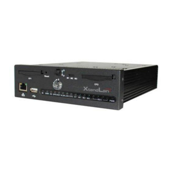
2 Overview and Controls This section provides information about front panel and rear panel. When you install this series DVR for the first time, please refer to this part first. 2.1 Front Panel The front panel is shown as in Figure 2-1. Figure 2-1 Please refer to the following sheet for front panel button information. -
Page 18: Hardware Mode
Otherwise it is off. CF card indication light The light is on when the CF card is working properly. Otherwise it is off. Working mode status indication light The corresponding working mode light is on when the system is in the specified working mode. -
Page 19: Connection Interface
Figure 2-2 Please refer to the following sheet for detailed information. Function 3G antenna port Please note only the unit of 3G module supports this function. SIM card socket Please note only the unit of 3G module supports this function. WIFI antenna port Please note only the unit of WIFI module supports this function. -
Page 20: Remote Control
Figure 2-3 2.4 Remote Control The remote control interface is shown as in Figure 2-4. X282H282H282H Please note remote control is not our standard accessory and it is not included in the accessory bag. Figure 2-4... -
Page 21: Mouse Control
Serial Name Function Number View Switch window Click it to input device serial number, so that you can control it. Number 0 to 9 Input password, channel or switch channel. Record Record Auxiliary button Enter Confirm button Menu Menu button Cancel button ... - Page 22 In input box, you can select input methods. Left click the corresponding button on the panel you can input numeral/English character (small/capitalized). Here ← stands for backspace button. _ stands for space button. In English input mode: _stands for input a backspace icon and ← stands for deleting the previous character.
-
Page 23: Virtual Keyboard & Front Panel
2.6 Virtual Keyboard & Front Panel 2.6.1 Virtual Keyboard The system supports two input methods: numeral input and English character (small and capitalized) input. Move the cursor to the text column, the text is shown as blue, input button pops up on the right. Click that button to switch between numeral input and English input (capitalized and small), Use >... -
Page 24: Installation And Connections
3 Installation and Connections Note: All the installation and operations here should conform to your local electric safety rules. 3.1 Check Unpacked DVR When you receive the DVR from the forwarding agent, please check whether there is any visible damage. The protective materials used for the package of the DVR can protect most accidental clashes during transportation. -
Page 25: Remove
Figure 3-2 3) Lock CF card. Now you can see an interface is shown as below after you firmly inserted the CF card. Please follow the direction arrow in Figure 3-3 to push the plastic handspike and then lock the CF card. Figure 3-3 3.3.2 Remove The rear panel is shown as below after you installed the CF card. -
Page 26: Connecting Power Supply
Figure 3-5 3) Push the CF card button and then you can see the card pops up. Please follow the arrowhead in Figure 3-8 to remove the CF card. Figure 3-6 After you removed the CF card, please push the plastic handspike following the arrowhead in Figure 3-7. -
Page 27: Connecting Video Output
The video input interface is BNC. The input video format includes: PAL/NTSC BNC(1.0V P- P , 75Ω. The video signal should comply with your national standards. The input video signal shall have high SNR, low distortion; low interference, natural color and suitable lightness. -
Page 28: Audio Output
Figure 3-8 The audio input cable is shown as in Figure 3-9. Please use this cable when your camera is the general BNC port. Figure 3-9 Please refer to the following sheet for detailed information. Audio/Video input cable (Aviation port 4p male port) Port Color and Definition Yellow BNC male port(Video input)... -
Page 29: Alarm Input And Output Connection
Adjust the layout to reduce happening of the squeaking. Please refer to Figure 3-10. It is for audio and video output. Figure 3-10 Audio/video output cable is shown as below. See Figure 3-11. You can use it when your monitor port is general BNC port. -
Page 30: Alarm Input And Output Details
c. For too long signal wires, 120Ω should be parallel connected between A, B lines on the far end to reduce reflection and guarantee the signal quality. d. “485 A, B” of DVR cannot parallel connect with “485 port” of other device. e. -
Page 31: Alarm Output Port
Please parallel connect the Ground of the DVR and the ground of the alarm detector. Please connect the NC port of the alarm sensor to the DVR alarm input(ALARM) Use the same ground with that of DVR if you use external power to the alarm device. Figure 3-13 3.7.3 Alarm Output Port ... -
Page 32: Rs485
The series DVR also support NKB operation. You can operate the DVR from the keyboard controls instead of using the control pad on the front panel of the unit. To connect a NKB keyboard to the DVR: 1. Assemble the KBD keyboard according to the instructions in its accompanying installation manual. 2. -
Page 33: Overview Of Navigation And Controls
4 Overview of Navigation and Controls 4.1 Login, Logout & Main Menu 4.1.1 Login Before you boot up the device, please make sure the CF card locks. You can see the CF card lock indication light is on. Turn the key to ACC, you can see power indication light becomes on and DVR boots up (DVR boots up might take several seconds). -
Page 34: Logout
Figure 4-2 4.1.3 Logout There are two ways for you to log out. One is from menu option: In the main menu, click shutdown button, you can see an interface is shown as below. See Figure 4-3 X293H293H29 3H285H28 5H285H29 2H292H Figure 4-3 There are several options for you. -
Page 35: Manual Record
We recommend replace battery regularly (such as one-year) to guarantee system time accuracy. Important! Before replacement, please save the system setup, otherwise, you may lose the data completely! 4.2 Manual Record 4.2.1 Live Viewing After you logged in, the system is in live viewing mode. You can see system date, time and channel name. - Page 36 Figure 4-5 4.2.2.3 Enable/disable record Please check current channel status: “○” means it is not in recording status, “●” means it is in recording status. You can use mouse or direction key to highlight channel number. See Figure 4-6. X296H296H296H Figure 4-6 4.2.2.4 Enable all channel recording Highlight ○...
-
Page 37: Search & Playback
You can see indication light in front panel turns on, system begins manual record now. Figure 4-8 4.2.2.5 Stop all channel recording Please highlight “ALL” after “Stop”. See Figure 4-9. X299H299H299H System stops all channel recording no matter what mode you have set in the menu (Main menu->Setting->Schedule) Figure 4-9 4.3 Search &... -
Page 38: Basic Operation
Figure 4-10 Please refer to the following sheet for more information. Serial Number Function Play Backward Stop Slow play Fast play Previous frame Next frame Volume Previous file Next channel Next file Previous channel Search Backup 4.3.2 Basic Operation 4.3.2.1 Playback There are various search modes: video type, channel number or time. -
Page 39: Calendar
Input time (h/m/s) in the time column and then click playback button, system can operate accurate playback. 4.3.2.4 Synchronized playback function when playback During playback process, click numeral key, system can switch to the corresponding channel video of the same time. 4.3.2.5 Digital zoom When the system is in playback mode, drag your mouse in the screen to select a section and then left click mouse to realize digital zoom. -
Page 40: Schedule
Figure 4-11 4.4 Schedule After system booted up, it is in default 24-hour regular mode. You can set record type and time in schedule interface. 4.4.1 hedule Menu In the main menu, from setting to schedule, you can go to schedule menu. See Figure 4-12. - Page 41 Figure 4-12 4.4.1.1 Quick Setup This function allows you to copy one channel setup to another. After setting in channel 1, you can click paste button and turn to channel 2 and then click copy button. You can finish setting for one channel and then click save button or you can finish all setup and then click save button to memorize all the settings.
-
Page 42: Snapshot
Figure 4-13 Playback or search in the redundant card. There are two ways for you to playback or search in the redundant disk. Set redundant disk(s) as read-only disk or read-write disk (Main menu->Advanced->HDD management). See Figure 4-13. System needs to reboot to get setup activated. Now you can search or playback file in redundant disk. - Page 43 Figure 4-14 4.4.2.2 Activation Snapshot Please follow the steps listed below to enable the activation snapshot function. After you enabled this function, system can snapshot when the corresponding alarm occurred . In Encode interface, click snapshot button to input snapshot mode, size, quality and frequency.
-
Page 44: Image Ftp
4.4.3 Image FTP In Network interface, you can set FTP server information. Please enable FTP function and then click save button. See Figure 4-16. Please boot up corresponding FTP server. Please enable schedule snapshot (Chapter 4.4.2.1) or activation snapshot (Chapter 4.4.2.2) first, now system can upload the image file to the FTP server. - Page 45 detection zone. After you completed the setup, please click ENTER button to exit current setup. Do remember click save button to save current setup. If you click ESC button to exit the region setup interface system will not save your zone setup. ...
-
Page 46: Video Loss
Figure 4-18 Figure 4-19 Figure 4-20 4.5.3 Video Loss Figure 4-17 , select video loss from the type list. You can see the interface is shown as X310H310H310H Figure 4-21.This function allows you to be informed when video loss phenomenon X311H311H31 1H occurred. -
Page 47: Camera Masking
Figure 4-21 4.5.4 Camera Masking When someone viciously masks lens, the system can alert you to guarantee video continuity. Camera masking interface is shown as in Figure 4-22 X312H312H312H Please refer to chapter 4.5.2 motion detection for detailed information. Note: In Detect interface, copy/paste function is only valid for the same type, which means you can not copy a channel setup in video loss mode to camera masking mode. -
Page 48: Alarm Setup
In the main menu, from Setting to Alarm, you can see alarm setup interface. See Figure 4- X314H314H314H 4.6.2 Alarm setup Alarm interface is shown as below. See Figure 4-23. X314H314H314H Alarm in: Here is for you to select channel number. ... -
Page 49: Backup
Figure 4-23 Figure 4-24 Figure 4-25 4.7 Backup DVR support USB device backup and network download. Here we introduce USB backup first. You can refer to Chapter 7 Web Client Operation for network download backup operation. 4.7.1 Detect Device Click backup button, you can see an interface is shown as in Figure 4-26.Here is for X319H319H319H289H28 9H289H29 6H you to view devices information. -
Page 50: Backup
Figure 4-26 4.7.1 Backup Select backup device and then set channel, file start time and end time. Click add button, system begins search. All matched files are listed below. System automatically calculates the capacity needed and remained. See Figure 4-27. X320H320H320H290H29 0H290H29 7H system only backup files with a √... -
Page 51: One-Button Backup
The file name format usually is: SN_CH+channel number+time Y+M+D+H+M+S. In the file name, the YDM format is the same as you set in general interface. (Main Menu ->Setting - >General).File extension name is .dav. You can visit our website to view listed CD-ROM brand. - Page 52 Figure 4-29 After completing all the setting please click save button. In one window display mode, right click mouse (click “Fn” Button in the front panel or click “Fn” key in the remote control). The interface is shown as in Figure 4-30 X323H323H323H293H293H2 93H300H Figure 4-30...
-
Page 53: Intelligent Positioning Key
Figure 4-31 , please click direction arrows (See Figure 4-32) to adjust PTZ X325H325H 325H295H 295H295H 302H X326H326H 326H296H 296H296H 303 position. There are total 8 direction arrows. You can use the remote control to set. Figure 4-32 4.8.3 3D Intelligent Positioning Key In the middle of the eight direction arrows, there is a 3D intelligent positioning key. -
Page 54: Preset Setup
Flip Reset Page switch Figure 4-35 Note: Preset, tour and pattern all need the value to be the control parameter. You can define it as you require. You need to refer to your speed dome user’s manual for Aux definition. In some cases, it can be used for special process. -
Page 55: Activate Patrol (Tour)
Figure 4-37 4.9.4 Activate Patrol (tour) Figure 4-34 , input patrol (tour) number in the No. blank and click patrol button X341H341H 341H311H 311H311H 318H 4.9.5 Pattern Setup Figure 4-34, click pattern button and then click “begin” button. The interface is shown as X342H342H 342H312H 312H312H 319H Figure 4-38. -
Page 56: Activate Auto Scan
4.9.8 Activate Auto Scan , click “Auto Scan” button, the system begins auto scan. Correspondingly, Figure 4-35 X351H351H 351H321H 321H321H 328H the auto scan button becomes Stop button. Click stop button to terminate scan operation. 4.10 Flip Figure 4-35 , click page switch button, you can see an interface is shown as below. See X352H352H 352H322H 322H322H 329H Figure 4-40 . -
Page 57: Understanding Of Menu Operations And Controls
5 Understanding of Menu Operations and Controls 5.1 Menu Tree This series DVR menu tree is shown as below. Backup Information HDD Info Version Online Users Setting General Encode Schedule RS232 Menu Network Alarm Detect Pan/ Tilt/Zoom Display Default Search Advanced HDD Management Alarm Output... -
Page 58: Setting
Figure 5-1 5.3 Setting In main menu, highlight setting icon and double click mouse. System setting interface is shown as below. See Figure 5-2. Figure 5-2 5.3.1 General General setting includes the following items. See Figure 5-3. System time: Here is for you to set system time ... -
Page 59: Encode
the next card is no empty, then system stops recording, If the current card is full and then next card is not empty, then system overwrites the previous files. Pack duration: Here is for you to specify record duration. The value ranges from 60 to 120 minutes. - Page 60 Please note some series do not support extra stream. Channel: Select the channel you want. Type: Please select from the dropdown list. There are two options: regular/alarm. Compression: System supports H.264. Resolution: System supports various resolutions, you can select from the dropdown list. For this model, main stream supports D1/CIF/QCIF.
-
Page 61: Schedule
Figure 5-7 5.3.3 Schedule Please refer to chapter 4.4 schedule. 5.3.4 RS232 RS232 interface is shown as below. There are five items. See Figure 5-8. Function: There are various devices for you to select. Console is for serial port or min-end platform to upgrade program. - Page 62 DHCP: It is to auto search IP. When enable DHCP function, you can not modify IP/Subnet mask /Gateway. These values are from DHCP function. If you have not enabled DHCP function, IP/Subnet mask/Gateway display as zero. You need to disable DHCP function to view current IP information.
- Page 63 Please note after you enabled this function, only the IP listed below can access current DVR. If you disable this function, all IP addresses can access current DVR. Figure 5-11 5.3.5.3 Multiple Cast Setup Multiple-cast setup interface is shown as in Figure 5-12. Figure 5-12 Here you can set a multiple cast group.
- Page 64 Like the single broadcast address of RFC1918 Can not be used in Internet transmission Used for multiple cast broadcast in limited space. Except the above mentioned addresses of special meaning, you can use other addresses. For example: Multiple cast IP: 235.8.8.36 Multiple cast PORT: 3666.
- Page 65 Pacific Time(P.T) GMT-8 American Mountain Time(M.T) GMT-7 American Central Time(C.T) GMT-6 American Eastern Time(E.T) GMT-5 Atlantic Time GMT-4 Brazil GMT-3 Middle Atlantic Time GMT-2 Figure 5-14 5.3.5.6 DDNS Setup DDNS setup interface is shown as in Figure 5-15. You need a PC of fixed IP in the internet and there is the DDNS software running in this PC. In other words, this PC is a DNS (domain name server).
- Page 66 Private DDNS function shall work with special DDNS server and special Professional Surveillance Software (PSS). 5.3.5.7 Email Email interface is shown as in Figure 5-16. Please input sender mailbox SMTP server IP address, port, user name, and password and sender mailbox, interval. The title content supports English character and Arabic number.
- Page 67 Figure 5-17 You can use a PC or FTP login tool to test setup is right or not. For example, you can login user ZHY to FTP://10.10.7.7 and then test it can modify H140H140H1 40H139H1 39H139H1 42H142HTU or delete folder or not. See Figure 5-18. Figure 5-18 System also supports upload multiple DVRs to one FTP server.
-
Page 68: Alarm
Please highlight the icon in front of Enable to activate FTP function. Here you can input FTP server address, port and remote directory. When remote directory is null, system automatically create folders according to the IP, time and channel. User name and password is the account information for you to login the FTP. File length is upload file length. - Page 69 Display setup interface is shown as below. See Figure 5-21. Transparency: Here is for you to adjust transparency. The value ranges from 128 to 255. Channel name: Here is for you to modify channel name. System max support 25-digit (The value may vary due to different series).
-
Page 70: Default
In tour mode, you can see the following interface. On the right corner, right click mouse or click shift button, you can control the tour. There are two icons: stands for enabling window switch stands for enabling window function. See Figure 5-23. Figure 5-23 5.3.10 Default Click default icon, system pops up a dialogue box. -
Page 71: Search
5.4 Search Please refer to chapter 4.3 Search. 5.5 Advanced Double click advanced icon in the main window, the interface is shown as below. See Figure 5-25. There are total eight function keys: HDD management, alarm output, abnormity, manual record, account, auto maintenance, TV adjust and Config backup. Figure 5-25 5.5.1 HDD Management Here is for you to view and implement CF card management. -
Page 72: Abnormity
Click alarm set button, the interface is shown as below. See Figure 5-27. (This interface is just like the abnormity setup). Please refer to chapter 5.5.2 for detailed information. Please highlight icon to select the corresponding function. Figure 5-27 5.5.2 Abnormity Abnormity interface is shown as in Figure 5-28. -
Page 73: Alarm Output
Figure 5-28 5.5.3 Alarm Output Here is for you to set proper alarm output. Please highlight icon to select the corresponding alarm output. After all the setups please click OK button, system goes back to the previous menu. See Figure 5-29. - Page 74 For the user account name and the user group, the string max length is 6-byte. The backspace in front of or at the back of the string is invalid. There can be backspace in the middle. The string includes the valid character, letter, number, underline, subtraction sign, and dot.
- Page 75 Figure 5-31 5.5.5.2 Add/Modify Group Click add group button, the interface is shown as below. See Figure 5-32. Here you can input group name and then input some memo information if necessary. There are total 60 rights such as control panel, shut down, real-time monitor, playback, record, record file backup, PTZ, user account, system information view, alarm input/output setup, system setup, log view, clear log, upgrade system, control device and etc.
-
Page 76: Auto Maintain
For convenient user management, usually we recommend the general user right is lower than the admin account. The modify user interface is similar to Figure 5-33. Figure 5-33 5.5.6 Auto Maintain Here you can set auto-reboot time, auto boot up time, auto shut down time, auto-delete old files and ACC delay setup. -
Page 77: Tv Adjust
5.5.7 TV Adjust Here is for you to adjust TV output setup. See Figure 5-35. Please drag slide bar to adjust each item. After all the setups please click OK button, system goes back to the previous menu. Figure 5-35 5.5.8 Config File Backup The configuration file backup interface is shown as below. -
Page 78: Hdd Information
5.6.1 HDD Information Here is to list CF card type, total space, free space, video start time and status. See Figure 5-38. ○ means current CF card is normal. X means there is error. - means there is no CF card. If CF card is damaged, system shows as “?”. -
Page 79: Log
5.6.3 Log Here is for you to view system log file. System lists the following information. See Figure 5-40. Log types include system operation, configuration operation, data management, alarm event, record operation, log clear and etc. Pleased select start time and end time, then click search button. You can view the log files. Please page up/down button to view if there are more than ten files. -
Page 80: Shutdown
Figure 5-42 5.7 Shutdown Double click shutdown button, system pops up a dialogue box for you to select. See Figure 5-43. Logout menu user: Log out menu. You need to input password when you login the next time. Shutdown: Exit the system and then turn off power. -
Page 81: About Auxiliary Menu
6 About Auxiliary Menu Go to Pan/Tilt/Zoom Menu In the one-window surveillance mode, right click mouse (click “fn” Button in the front panel or click AUX key in the remote control). The interface is shown as below: See Figure 6-1 X397H397H397H36 7H367H3 67H374H3 3 7H Figure 6-1 Click Pan/Tilt/Zoom, the interface is shown as in... -
Page 82: Preset /Patrol / Pattern /Border Function
Figure 6-4 6.2 Preset /Patrol / Pattern /Border Function Figure 6-2 click the set button. The interface is shown as X402H402H 402H372H 372H372H 379H342H below: Here you can set the following items: Preset Patrol Pattern Border Figure 6-5 Figure 6-2 , click page switch button, you can see an interface as in... -
Page 83: Activate Preset
Figure 6-5 , click preset button and input preset number. The interface is shown as in X409H409H 409H379H 379H379H 386H349H Figure 6-7 X410H410H41 0H380H38 0H380H38 7H350H Add this preset to one patrol number Figure 6-7 6.2.2 Activate Preset Figure 6-6 please input preset number in the No. -
Page 84: Activate Pattern Function
6.2.6 Activate Pattern Function Figure 6-6 input mode value in the No. blank, and click pattern button. X419H419H 419H389H 389H389H 396H359H 6.2.7 Border Setup Figure 6-5 , click border button. The interface is shown as in Figure 6-10 X420H420H 420H390H 390H390H 397H360H X421H421H421H391H39 1H391H39 8H361H Please go to Figure 6-2... -
Page 85: Web Operation
7 WEB OPERATION Please note all the operations here are based on our 4-ch DVR. There might be slightly difference in the interface due to different series. 7.1 Network Connection Before web client operation, please check the following items: Network connection is right ... - Page 86 Figure 7-2 After installation, the interface is shown as below. See Figure X430H430H430H4 00H400H4 00H407H3 70H . Please input your user name and password. Default factory name is admin and password is admin. Note: For security reasons, please modify your password after you first login. Figure 7-3 After you logged in, you can see the main window.
- Page 87 Section 1: there are five function buttons: configuration (chapter 7.3), search (chapter 7.4), alarm (chapter 7.5), about (chapter 7.6), log out (chapter 7.7). Section 2: there are channel number and three function buttons: start dialog and local play, refresh.
-
Page 88: Monitor Channel Menu Tree
7.3 Monitor Channel Menu Tree The monitor channel menu tree is shown as in Figure 7-7. Figure 7-7 Monitor Channel Menu Tree Please refer to the following sheet for detailed information. Parameter Function Channel 1 Monitor channel 1 This series product supports main stream and extra stream. ... - Page 89 5 6 7 8 9 10 Figure 7-8 Real-time Monitor Please refer to the following sheet for monitor window parameter information. Parameter Function 1: Device IP address. Display 2: Channel number. device 3: Bit stream. information 4: Stream decode type.
-
Page 90: System Menu
When you click local record button, the system begins Local recording. The recorded file is saved to system folder: \ record RecordDownload(default). You can go to chapter 2.7 to modify the local record save path. The playback bar is shown as below. 1- Playback process control 2- Play 3- Pause... -
Page 91: Ptz
7.5.1 PTZ Please note current series product does not support this function. Before PTZ operation, please make sure you have properly set PTZ protocol. (Please refer to chapter 7.3.2 Setting-> Pan/Tilt/Zoom). Click PTZ button, the interface is shown as in Figure 7-11 X437H437H437H4 07H407H4 07H414H3 77H 3D Intelligent Positioning... - Page 92 Figure 7-12 7.5.1.4 Auto Scan Figure 7-12 , move the camera to you desired location and then click left limit X439H439H 439H409H 409H409H 416H379H button. Then move the camera again and then click right limit button to set a right limit. 7.5.1.5 Pattern Figure 7-12 , you can input pattern value and then click start record button to begin...
-
Page 93: Color
Figure 7-13 7.5.2 Color Click color button in section 3, the interface is shown as Figure 7-14 X444H444H44 4H414H41 4H414H4 21H384H Here you can select one channel and then adjust its brightness, contrast, hue and saturation. (Current channel border becomes green). Or you can click default button to use system default setup. -
Page 94: Configure
Figure 7-16 Click record path button, you can see an interface is shown as in Figure 7-17 X448H448H448H418 H418H41 8H425H38 8H Please click choose button to modify path. Figure 7-17 Click reboot button, system pops up the following dialogue box. See Figure 7-18, Please click OK to reboot. - Page 95 Figure 7-19 7.6.1.2 HDD information Here you can view local CF card storage status and network status including, free capacity and total capacity. See Figure 7-20 X450H450H450H420H 420H420 H427H39 0H Figure 7-20 7.6.1.3 Log Here you can view system log. See Figure 7-21 X451H451H451H4 21H421H 421H428H 391H...
-
Page 96: System Configuration
Figure 7-21 Click backup button, the interface is shown as in Figure 7-22 X452H452H452H422 H422H42 2H429H392H Figure 7-22 Please refer to the following sheet for log parameter information. Parameter Function Log types include: system operation, configuration operation, data Type management, alarm event, record operation, user management, log clear and file operation. - Page 97 7.6.2.1 General Setup Here you can set system time, record length, video format and etc. See Figure 7-23 X453H453H453H4 23H423H4 23H430H3 93H Figure 7-23 Figure 7-24 Figure 7-25 Please refer to the following sheet for detailed information. Parameter Function Here is for you to modify system time. Please click Save button after System your completed modification Time...
- Page 98 Sync PC You can click this button to save the system time as your PC current time. Here you can select data format from the dropdown list. Data Format Please select separator such as – or /. Data Separator There are two options: 24-H and 12-H. Time Format Here you can set day night save time begin time and end time.
- Page 99 Figure 7-26 Figure 7-27 Please refer to the following sheet for detailed information. Parameter Function Here is for you to select a monitor channel. Channel Here is to display current channel name. You can modify it. Channel Name Compression H.264 Main Stream It includes main stream, motion stream and alarm stream.
- Page 100 Parameter Function Audio/Video For the main stream, recorded file only contains video by default. You need to draw a circle here to enable audio function. For extra stream, you need to draw a circle to select the video first and then select the audio if necessary.
- Page 101 If you have completed the setup for channel 1, you can click 3 to copy current setup to channel 3. Or you can click 2, 3, and 4 to copy current setup to channel 2, channel 3 and channel 4. Figure 7-28 7.6.2.3 Schedule Here you can set different periods for various days.
- Page 102 Figure 7-30 Please refer to the following sheet for detailed information. Parameter Function Please select a channel first. Channel Pre-record Please input pre-record value here. System can record several seconds video before activating the record operation into the file. (Depends on data size). Setup ...
- Page 103 Figure 7-31 Please refer to the following sheet for detailed information. Parameter Function RS232 There is only one option: COM 01. It is corresponding to RS232. Console is for debug. Control keyboard: Switch between RS232 and control Function keyboard. Network keyboard: COM control protocol. You can use network keyboard to control IPC via COM.
- Page 104 Figure 7-32 Please refer to the following sheet for detailed information. Parameter Function Ethernet Please select the network card first. DHCP Dynamically get IP address. You can get the device IP from the DHCP server if you enabled this function. Device Name The device ID in the network.
- Page 105 Figure 7-33 Please refer to the following sheet for detailed information. Parameter Function Input server address and then enable this function. SMTP Server You can enable SSL encryption function to guarantee data SSL enable safety. Port Default value is 25. You can modify it if necessary. The sender email account user name.
- Page 106 Figure 7-34 Please refer to the following sheet for detailed information. Parameter Function Server Type You can select DDNS protocol from the dropdown list and then enable DDNS function. The private DDNS protocol means you use your self-defined private protocol to realize DDNS function. Server IP DDNS server IP address Server Port...
- Page 107 Figure 7-35 Please refer to the following sheet for detailed information. Parameter Function Please select network storage protocol and then enable NAS enable NAS function. Server IP Input remote storage server IP address. Input Remote storage server port number. Port Log in user account.
- Page 108 transmission only and its port shall be 123.The update interval ranges from 1 to 65535. Default value is 10 minutes. Figure 7-36 You can refer to the following sheet for time zone information. City /Region Name Time Zone London GMT+0 Berlin GMT+1 Cairo...
- Page 109 Figure 7-37 Please refer to the following sheet for detailed information. Parameter Function Server IP Please input the server IP that receive the alarm. Port The value ranges from 0 to 65535. The option ranges from Sunday to Saturday. The option also includes;: none/every day.
- Page 110 Figure 7-38 7.6.2.6 Alarm Alarm setup interface is shown as in Figure 7-39. X467H467H467H4 37H437H4 37H444H4 07H Please make sure you have connected the corresponding alarm output device such as the light, buzzer and etc. Figure 7-39 Please refer to the following sheet for detailed information. Parameter Function...
- Page 111 Parameter Function Event It includes local alarm/network alarm. Type Local alarm: Device detects alarm from input port. Network: Device detects alarm from network. Alarm in Select corresponding alarm channel. Enable You need to draw a circle here so that system can detect the alarm signal.
- Page 112 Figure 7-40 Figure 7-41 Please refer to the following sheet for detailed information. Parameter Function Event There are three types: Motion detection/video loss/Camera Masking. Type Channel Select channel name from the dropdown list. Enable You need to draw a circle to enable motion detection function. Sensitivity There are six levels.
- Page 113 Parameter Function Region There are six levels. The sixth level has the highest sensitivity. Region: If you select motion detection type, you can click this button to set motion detection zone. The interface is shown as in X469H469H469H439H439H439H446H409HFigure 7-41. There are PAL 22X18/NTSC 22X15 zones.
- Page 114 Figure 7-42 Please refer to the following sheet for detailed information. Parameter Function You can select monitor channel from the dropdown list. . Channel Select the corresponding dome protocol.(such as PELCOD) Protocol Set corresponding dome address. Default value is 1. Please note your Address setup here shall comply with your dome address;...
-
Page 115: Advanced
Figure 7-43 Please refer to the following sheet for detailed information. Parameter Function Select All Restore factory default setup. Export Export system configuration to local PC. Configuration Import Import configuration from PC to the system. Configuration 7.6.3 Advanced 7.6.3.1 HDD Management HDD management includes net storage management and local storage management. - Page 116 Figure 7-44 Please refer to the following sheet for detailed information. Parameter Function Format Clear data in the CF card. Read/write Set current card as read/write Read only Set current card as read. Recover Recover dada after an error occurs. Please note system needs to reboot to activate current setup.
- Page 117 Important The alarm output port should not be connected to high power load directly (It shall be less than 1A) to avoid high current which may result in relay damage. Please use the co contactor to realize the connection between the alarm output port and the load. Please refer to the following sheet for detailed information.
- Page 118 Figure 7-47 7.6.3.5 Auto Maintenance Here you can select auto reboot and auto delete old files interval from the dropdown list. See Figure 7-48 X476H476H47 6H446H44 6H446H45 3H416H Figure 7-48 7.6.3.6 Snapshot Snapshot interface is shown as in Figure 7-49 X477H477H477H447H 447H447H 454H417 H...
- Page 119 Figure 7-49 Please refer to the following sheet for detailed information. Parameter Function Channel It is the monitor channel. There are two modes: Timing and activation. Snapshot mode Frame rate You can select from the dropdown list. You can select from the dropdown list. Resolution You can select from the dropdown list.
- Page 120 Please refer to the following sheet for detailed information. Parameter Function Event The abnormal events include: no disk, no space, disk error, net error. Type You need to draw a circle to enable this function. Normal The corresponding alarm activation output channel when alarm occurs, There are 7 channels.
-
Page 121: Additional Function
Parameter Function Auto boot You can check the box to enable this function and then input the auto boot up time. Auto You can check the box to enable this function and then input the auto shutdown shutdown time. Auto Please input the auto shutdown delay time here. - Page 122 Figure 7-52 DNS 7.6.4.2 Auto Register Auto register interface is shown as below. See Figure7-53. Figure 7-53 Auto Register Please refer to the following sheet for detailed information. Parameter Function Enable Enable auto register function.
- Page 123 Device management server number. Device management server IP address. Port Server port number. Device ID Device ID in the device management server. 7.6.4.3 CDMA/GPRS Please note only the unit of 3G module supports this function. The CDMA/GPRS interface is shown as below. See Figure 7-54. Figure 7-54 CDMA/GPRS Figure 7-55 Schedule Setup...
- Page 124 Please refer to the following sheet for detailed information. Parameter Function Wireless type You can select from the dropdown list. Enable Please check the box to enable the selected function. Please input the connection name here. There are two types for the device to connect to the 3G. It includes Dial/SMS activate state the dial-up and sms.
- Page 125 Refresh Click this button to get device latest configuration. 7.6.4.4 Mobile Configuration Please note only the unit of 3G module supports this function. Mobile configuration interface is shown as in Figure 7-56. Figure 7-56 Mobile Configuration Please refer to the following sheet for detailed information. Parameter Function Send event...
-
Page 126: Search
There are two types: SMS and MMS. Message type Right now system supports SMS only. Title You can input message subject here. Event message System can save the message receiver number so that device can send save out alarm (motion detect) message to the specified mobile phone(s). SMS save System can save the mobile phone number which can send out the message to activate the device. - Page 127 Figure 7-57 Select the file(s) you want to download and then click download button, system pops up a dialogue box shown as in Figure 7-58, then you can specify file name and path to X480H480H480H4 50H450H4 50H download the file(s) to your local pc. Figure 7-58 Now you can see system begins download and the download button becomes stop button.
- Page 128 Figure 7-59 When download completed, you can see a dialogue box shown as in Figure 7-60. Please click OK to exit. Figure 7-60 Figure 7-61 Watermark...
- Page 129 Please refer to the following sheet for detailed information. Type Parameter Function Type Record Search general record, alarm record and motion detection record. Alarm Search alarm record. Motion Search motion detection record. Detection Local Search local record. Snapshot Search snapshot file. Card This function is not available in current device.
-
Page 130: Alarm
4: Slow play 5: Fast play Playback device IP address and channel number. Playback control bar Figure 7-62 7.8 Alarm Click alarm function, you can see an interface is shown as in Figure 7-63. X483H483H483H453H 453H453H Here you can set device alarm type and alarm sound setup. Please make sure you have enabled the alarm upload function at the device-end. -
Page 131: About
Figure 7-63 Please refer to the following sheet for detailed information. Please make sure current device can upload the alarm. Type Parameter Function Alarm Video loss System alarms when video loss occurs. Type Motion detection System alarms when motion detection alarm occurs, Disk full System alarms when CF card is full. -
Page 132: Log Out
Figure 7-64 7.10 Log out Click log out button, system goes back to log in interface. See Figure 7-65 X485H485H485H455H45 5H455H You need to input user name and password to login again. Figure 7-65 7.11 Un-install Web Control You can use web un-install tool “uninstall web.bat” to un-install web control. Please note, before you un-installation, please close all web pages, otherwise the un- installation might result in error. -
Page 133: Professional Surveillance System
8 Professional Surveillance System Besides Web, you can use our Professional Surveillance Software (PSS) to login the device. For detailed information, please refer to PSS user’s manual. - Page 134 9 FAQ 1. DVR can not boot up properly. There are following possibilities: Input power is not correct. Power connection is not correct. Power switch button is damaged. Program upgrade is wrong. CF card malfunction or something wrong with CF card. ...
- Page 135 DVR and monitor resistance is not compatible. Video transmission is too long or degrading is too huge. DVR color or brightness setup is not correct. 7. Can not search local records. There are following possibilities: CF card connection is loose or the installation is improper. ...
- Page 136 PTZ decoder and DVR protocol is not compatible. PTZ decoder and DVR address is not compatible. When there are several decoders, please add 120 Ohm between the PTZ decoder A/B cables furthest end to delete the reverberation or impedance matching. Otherwise the PTZ control is not stable.
- Page 137 Burner and DVR are in the same data cable. System uses too much CPU resources. Please stop record first and then begin backup. Data amount exceeds backup device capacity. It may result in burner error. Backup device is not compatible. ...
- Page 138 24. When I delete the local setup interface via the COM control interface, the local IP restore the default setup. Please note this function is for R&D engineer to debug. Please use the RESTE button of the interface to clear the setup. 25.
- Page 139 Please unplug the power cable when you remove the audio/video signal cable, RS232 or RS485 cable. Please check the DVR is secured firmly and horizontally. Please make sure the anti- vibration component can work properly. Please check and maintain the DVR regularly.
Need help?
Do you have a question about the DVR-411AUTO and is the answer not in the manual?
Questions and answers