Table of Contents
Advertisement
DMC-TZ35EB
Model No.
DMC-TZ35EE
DMC-TZ35EF
DMC-TZ35EG
DMC-TZ35EP
DMC-TZ35GA
DMC-TZ35GC
DMC-TZ35GN
DMC-TZ35SG
DMC-TZ36EG
DMC-ZS25P
DMC-ZS25PC
DMC-ZS25PU
DMC-ZS25GK
Colours
(S)....................Silver Type (except DMC-TZ35GN)
(K)....................Black Type
© Panasonic Corporation 2013.
Unauthorized copying and distribution is a violation
of law.
ORDER NO.DSC1302001CE
B26
Digital Camera
Advertisement
Table of Contents

Subscribe to Our Youtube Channel
Related Manuals for Panasonic Lumix DMC-TZ35EB


Summary of Contents for Panasonic Lumix DMC-TZ35EB
- Page 1 ORDER NO.DSC1302001CE Digital Camera DMC-TZ35EB Model No. DMC-TZ35EE DMC-TZ35EF DMC-TZ35EG DMC-TZ35EP DMC-TZ35GA DMC-TZ35GC DMC-TZ35GN DMC-TZ35SG DMC-TZ36EG DMC-ZS25P DMC-ZS25PC DMC-ZS25PU DMC-ZS25GK Colours (S)....Silver Type (except DMC-TZ35GN) (K)....Black Type © Panasonic Corporation 2013. Unauthorized copying and distribution is a violation of law.
-
Page 2: Table Of Contents
TABLE OF CONTENTS PAGE PAGE 1 Safety Precautions -----------------------------------------------3 1.1. General Guidelines ----------------------------------------3 1.2. Leakage Current Cold Check ---------------------------3 1.3. Leakage Current Hot Check (See Figure 1)---------3 1.4. How to Discharge the Capacitor on Flash P.C.B.----------------------------------------------------------4 2 Warning --------------------------------------------------------------5 2.1. Prevention of Electrostatic Discharge (ESD) to Electrostatic Sensitive (ES) Devices ---------------5 2.2. -
Page 3: Safety Precautions
1 Safety Precautions 1.1. General Guidelines 1.3. Leakage Current Hot Check (See Figure 1) 1. IMPORTANT SAFETY NOTICE There are special components used in this equipment 1. Plug the AC cord directly into the AC outlet. Do not use which are important for safety. These parts are marked by an isolation transformer for this check. -
Page 4: How To Discharge The Capacitor On Flash P.c
1.4. How to Discharge the Capacitor on Flash P.C.B. CAUTION: 1. Be sure to discharge the capacitor on Flash P.C.B. 2. Be careful of the high voltage circuit on Flash P.C.B. when servicing. [Discharging Procedure] 1. Refer to the disassemble procedure and remove the necessary parts/unit. 2. -
Page 5: Warning
2 Warning 2.1. Prevention of Electrostatic Discharge (ESD) to Electrostatic Sensitive (ES) Devices Some semiconductor (solid state) devices can be damaged easily by static electricity. Such components commonly are called Electrostatically Sensitive (ES) Devices. The following techniques should be used to help reduce the incidence of component damage caused by electrostatic discharge (ESD). -
Page 6: How To Replace The Lithium Battery
Note: The lithium battery is a critical component. (Type No.: ML-421S/DK Manufactured by Energy Company, Panasonic Corporation.) It must never be subjected to excessive heat or discharge. It must therefore only be fitted in equipment designed specifically for its use. -
Page 7: Service Navigation
3 Service Navigation 3.1. Introduction This service manual contains technical information, which will allow service personnel's to understand and service this model. Please place orders using the parts list and not the drawing reference numbers. If the circuit is changed or modified, the information will be followed by service manual to be controlled with original service manual. 3.2. -
Page 8: General Description About Lead Free Solder (Pbf)
3.3. General Description About Lead Free Solder (PbF) The lead free solder has been used in the mounting process of all electrical components on the printed circuit boards used for this equipment in considering the globally environmental conservation. The normal solder is the alloy of tin (Sn) and lead (Pb). On the other hand, the lead free solder is the alloy mainly consists of tin (Sn), silver (Ag) and Copper (Cu), and the melting point of the lead free solder is higher approx.30 °C (86 °F) more than that of the normal solder. -
Page 9: How To Define The Model Suffix (Ntsc Or Pal Model)
How to Define the Model Suffix (NTSC or PAL model) There are seven kinds of DMC-TZ35/TZ36/ZS25, regardless of the colours. • a) DMC-TZ35 (Japan domestic model.) /SG • b) DMC-ZS25P/PC • c) DMC-TZ35EB/EF/EG/EP, TZ36EG • d) DMC-TZ35EE • e) DMC-TZ35GN • f) DMC-ZS25GK •... -
Page 10: Initial Settings
3.4.2. INITIAL SETTINGS: After replacing the Main P.C.B., make sure to perform the initial settings after achieving the adjustment by ordering the following procedure in accordance with model suffix of the unit. 1. IMPORTANT NOTICE: Before proceeding Initial settings, be sure to read the following CAUTIONS. 2. - Page 11 • Step 4. Display the "INITIAL SETTINGS" menu: Note: If the unit is other than PROGRAM AE mode, it does not display the initial settings menu. While keep pressing MENU/SET and "RIGHT of Cursor button" simultaneously, turn the Power off. The "INITIAL SETTINGS"...
- Page 12 1) As for your reference, major default setting condition is as shown in the following table. • Default setting (After "INITIAL SETTINGS") MODEL VIDEO OUTPUT LANGUAGE DATE REMARKS DMC-TZ35 (Japan domestic model) NTSC Japanese Year/Month/Date DMC-TZ35EB English Date/Month/Year DMC-TZ35EE Russian Date/Month/Year DMC-TZ35EF French Date/Month/Year DMC-TZ35EG English...
-
Page 13: Specifications
4 Specifications The following specification is for DMC-ZS25PC. Some specifications may differ depending on model suffix. -
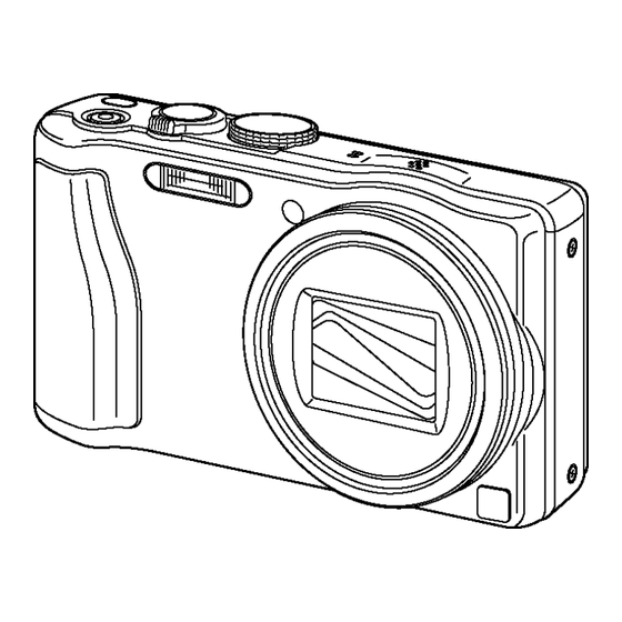
Page 14: Location Of Controls And Components
5 Location of Controls and Components The following description is for DMC-ZS25PC. Some description may differ depending on model suffix. -
Page 15: Service Mode
6 Service Mode 6.1. Error Code Memory Function 1. General description This unit is equipped with history of error code memory function, and can be memorized 16 error codes in sequence from the latest. When the error is occurred more than 16, the oldest error is overwritten in sequence. The error code is not memorized when the power supply is shut down forcibly (i.e.,when the unit is powered on by the battery, the battery is pulled out) The error code is memorized to Flash ROM when the unit has just before powered off. - Page 16 3. Error Code List The error code consists of 8 bits data and it shows the following information. Attribute Main item Sub item Error code Contents (Upper) Error Indication High Low 4 Check point (Lower) Detecting Part/Circuit 4bits bits device LENS Lens drive 18*0...
- Page 17 Attribute Main item Sub item Error code Contents (Upper) Error Indication High Low 4 Check point (Lower) Detecting Part/Circuit 4bits bits device Adj.History 19*0 2000 OIS adj. Yaw direction amplitude error (small) OIS ADJ OIS ADJ 3000 OIS adj. Pitch direction amplitude error (small) 4000 OIS adj.
- Page 18 Important notice about "Error Code List" 1) About "*" indication: The third digit from the left is different as follows. +.In case of 0 (example: 18 0 01000) When the third digit from the left shows "0", this error occurred under the condition of INITIAL SETTINGS has been completed. It means that this error is occurred basically at user side.
-
Page 19: Service Fixture & Tools
7 Service Fixture & Tools 7.1. Service Fixture and Tools The following Service Fixture and tools are used for checking and servicing this unit. 7.2. When Replacing the Main P.C.B. After replacing the Main P.C.B., be sure to achieve adjustment. -
Page 20: Service Position
7.3. Service Position This Service Position is used for checking and replacing parts. Use the following Extension cables for servicing. Parts No. Connection Form VFK1895 PP9006 (MAIN P.C.B.) - PS9201 (OPERATION P.C.B.) 40PIN B to B RFKZ0545 PP9901 (TOP P.C.B.) - PS9904 (Main P.C.B.) 34PIN B to B VFK1906 PP8001 (FLASH P.C.B.) - PS9903 (TOP P.C.B.) -
Page 21: Disassembly And Assembly Instructions
8 Disassembly and Assembly Instructions 8.1. Disassembly Flow Chart 8.2. P.C.B. Location... -
Page 22: Disassembly Procedure
8.3. Disassembly Procedure Item Fig. Removal Rear Case Unit Fig. D1-1 4 screws (A) 1 screw (B) Rear Case Unit Front Case Unit Fig. D2 1 screw (C) 1 Locking tab Front Case Unit Side Ornament (R), Side Fig. D3 3 Locking tabs Ornament (L) Unit Side Ornament (R), Side Ornament (L) Unit... - Page 23 8.3.1. Removal of the Rear Case Unit Protection sheet attaching procedure: 1. Remove the protection sheet from the base sheet and fold the flap of the separator to the two-sided tape side. Fig. D1-2 2. Slightly tilt the separator to prevent the two-sided tape's adhesion.
- Page 24 8.3.2. Removal of the Front Case Unit 3. Press the separator firmly and attach the two-sided tape. 4. Remove the separator slowly and carefully. Check if there is nothing sticking out from the rear case window frame. Fig. D1-4 Fig. D2 8.3.3.
- Page 25 8.3.4. Removal of the Operation P.C.B. 8.3.5. Removal of the LCD Unit Fig. D5 Fig. D4...
- Page 26 8.3.6. Removal of the Frame Plate Unit 8.3.7. Removal of the Lens Unit Fig. D6 Fig. D7...
- Page 27 8.3.8. Removal of the Main P.C.B. 8.3.9. Removal of the Top Case Unit Fig. D9 Fig. D8...
- Page 28 8.3.10. Removal of the Top P.C.B. 8.3.11. Removal of the Flash Unit, Flash P.C.B. Fig. D11 Fig. D10...
- Page 29 8.3.12. Removal of the Battery Case Fig. D12...
-
Page 30: Lens Disassembly Procedure
8.4. Lens Disassembly Procedure 2. Remove the Shutter FPC. 3. Remove the Lens FPC from the positioning boss. Precaution: 4. Remove the Master Flange Unit and Drive Gear. 1. Do not remove the MOS when disassembling or re- assembling the lens in order to maintain it clean. When remove it, refer to item "8.6". - Page 31 8.4.2. Removal of the Drive Frame Unit, 8.4.3. Removal of the Decorative Frame Decorative Frame Unit, Outside Unit, Outside Cam Frame, 1st Lens Cam Frame, 1st Lens Frame Unit, Frame Unit, 2nd Lens Frame Unit, 2nd Lens Frame Unit, 3rd Lens 3rd Lens Frame Unit, Straight Frame Unit, Straight Frame and Frame and Both Side Cam Frame...
- Page 32 8.4.4. Removal of the Outside Cam 8.4.5. Removal of the 1st Lens Frame Frame, 1st Lens Frame Unit, 2nd Unit, 2nd Lens Frame Unit, 3rd Lens Frame Unit, 3rd Lens Frame Lens Frame Unit, Straight Frame Unit, Straight Frame and Both Side and Both Side Cam Frame Cam Frame •...
- Page 33 8.4.7. Removal of the 2nd Lens Frame 8.4.8. Removal of the 3rd Lens Frame Unit Unit 1. Hold the Straight Frame and turn it in the arrow (1) so that • Push the 3rd Lens Frame Unit in the arrow direction from the mark (2nd Lens Frame Unit) meets the mark front of the Lens, and remove the 3rd Lens Frame Unit from...
-
Page 34: Assembly Procedure For Lens (Revised Version)
8.5. Assembly Procedure for Lens 3. Turn the Straight Frame about 90 degrees in the arrow direction so that the mark of Straight Frame comes (Revised Version) close to the mark of Both Side Cam Frame. *As the drawing below indicates, align the Grooves of 8.5.1. - Page 35 2. Insert the 2nd Lens Frame Unit as the drawing below 3. While pushing the 3rd Lens Frame Unit and the 2nd Lens indicated. Frame Unit, turn the Straight Frame Unit in the arrow *Align the mark of the 2nd Lens Frame Unit with the direction to the end.(about 30 degree) one of the Straight Frame Unit, then put the each Cam *Need to confirm that the two Lens Frames move...
- Page 36 8.5.3. Insert the 1st Lens Frame Unit and 2. Move the mark of the Both Side Cam Frame Unit closer to the mark of the Outside Cam Frame Unit, then turn the Outside Cam Frame Unit the 1st Lens Frame Unit just a bit in the arrow 1.
- Page 37 8.5.4. Insert the Decorative Frame Unit 4. Turn the Both Side Cam Frame Unit to the end in the arrow direction while holding the Outside Cam Frame 1. Hold the Straight Key (Both Side Cam Frame), turn it in Unit. (About 118.5 degrees) the arrow direction and align with the Straight Key *Confirm that 1st Lens Frame Unit does not rotate when (Outside Cam Frame).
- Page 38 8.5.5. Insert the Drive Frame Unit 3. Align the mark (Decorative Frame) with the Straight Key (Both Side Cam Frame), and install the Unit of • Align the mark (Drive Frame and Outside Cam Frame), Outside Cam Frame,1st Lens Frame Unit, 2nd Lens and install the Unit of Decorative Frame Unit, Outside Cam Frame Unite, 3rd Lens Frame Unite, Straight Frame and Frame, 1st Lens Frame Unit, 2nd Lens Frame Unite, 3rd...
- Page 39 8.5.6. Insert the Fix Frame Unit 8.5.7. Insert the Master Flange Unit 1. Install the Drive Gear to the Fix Cam Frame Unit. Note: (When Installing) Refer to "The Application of Grease Method" when installing 2. Align the mark (Outside Cam Frame and Drive Frame the Master Flange Unit.
-
Page 40: Removal Of The Mos Unit
8.6. Removal of the MOS Unit 5. Join the Zoom Motor Unit to the Boss, and install to the Fix Cam Frame. When remove the MOS Unit once (the Torx screw (A) is loosened even a little), the optical tilt adjustment is required. -
Page 41: Measurements And Adjustments
9 Measurements and Adjustments 9.1. Introduction When servicing this unit, make sure to perform the adjustments necessary based on the part(s) replaced. When trouble occurs, it is recommended to backup the Flash-rom data before disassembling the unit. NOTE: (When replacing the Lens unit, Master flange unit and MOS unit) •... - Page 42 9.2.2. Flash-Rom Data Backup Number of necessary adjustment items decreases by copying the backup data to new Main P.C.B. when adjustment data in old Main P.C.B. can be read by ROM_BACKUP "DSC→SD". It is recommended to backup the Flash-rom data as the way of return when trouble occurs before disassembling the unit depending on each case.
-
Page 43: Details Of Electrical Adjustment
9.3. Details of Electrical Adjustment 9.3.1. How to execute the Electrical Adjustment It is not necessary to connect the camera to a PC to perform adjustments. "Flag reset operation" and "Initial setting operation" are required when carrying out the alignment, follow the procedure below. 9.3.1.1. - Page 44 9.3.1.3. Execute Adjustment 1. Perform step "9.3.1.1." to "9.3.1.2.", to reset the OIS flag status "F" (Set) to "0" (Reset). 2. Press DISPLAY button after Flag reset. OIS Adjustment screen is displayed on the LCD panel. (Refer to Fig.3-4) 3. Press the shutter button. The adjustment will start automatically.
- Page 45 9.3.2. Adjustment Specifications The following matrix table shows the relation between the replaced part and the Necessary Adjustment. When a part is replaced, make sure to perform the necessary adjustment(s) in the order indicated. The table below shows all the information necessary to perform each adjustment.
- Page 46 IMPORTANT NOTICE (After replacing the Main P.C.B.) After replacing the Main P.C.B., make sure to perform the "INITIAL SETTINGS" first, then release the "INITIAL SETTINGS" in order to proceed the electrical adjustment. Note: 1. If electrical adjustment or data re-writing is executed before "INITIAL SETTINGS", suffix code list is never displayed, and it cannot be chosen suitable suffix code.
-
Page 47: After Adjustment
9.4. After Adjustment 9.4.1. Initial Setting Since the initial setting has been released to execute the built-in adjustment software, it should be set up again before shipping the camera to the customer. Refer to the procedure described in "3.4.2. INITIAL SETTINGS" for details. [IMPORTANT] 1. -
Page 48: Maintenance
10 Maintenance 10.1. Cleaning Lens, Viewfinder and LCD Panel Do not touch the surface of lens, Viewfinder and LCD Panel with your hand. When cleaning the lens, use air-Blower to blow off the dust. When cleaning the LCD Panel, dampen the lens cleaning paper with lens cleaner, and the gently wipe the their surface. Note: The Lens Cleaning KIT;... -
Page 49: Block Diagram
11 Block Diagram 11.1. Overall Block Diagram (24mm - 480mm) IC6002 IC3101 FLASH ROM /1Gbit 1/2.33" 17.5 MEGA PIX (27MHz) ZOOM IRIS SHUTTER OIS UNIT FOCUS CARD HDMI TERMINAL IC9101 MOTOR DRIVE, OIS DRIVE & PRE PROCESS MICROPHONE IC9101 IC7101 VIDEO OUT &... -
Page 50: System Control Block Diagram
11.2. System Control Block Diagram IC6001 (VENUS ENGINE) OPERATION P.C.B. PP9006 PS9201 CROSS KEY IN AB18 RIGHT DOWN LEFT S9203 S9202 S9201 S9204 PP9006 PS9201 REAR KEY IN AC20 DELETE DISPLAY MENU PLAY EXPOSURE D9102 S9208 S9207 S9206 S9205 S9210 PP9006 PS9201 PLAY... -
Page 51: Audio/Video Process/ Hdmi Block Diagram
11.3. Audio/Video Process/ HDMI Block Diagram IC6002 LCD UNIT (FLASH ROM/ SDRAM) (Type of LCD Drive inclusion) MAIN OPERATION PP9006 PS9201 FP9202 512Mbit(4Mx32bitx4pcs) DCLK X-BUFFERS 512M + 16M Bits A9-A25 LATCHES PP9006 PS9201 FP9202 NAND FLASH & DECODERS BANK0 BANK2 ARRAY PP9006 PS9201... -
Page 52: Lens Drive Block Diagram
11.4. Lens Drive Block Diagram IC6001 IC7101 FOCUS ENC FP9005 (VENUS ENGINE) (GYRO SENSOR) FHP LED FZHP ABS G FHP GYRO SCK 9 SCLK CD BARREL ENC GYRO DI MISO G ZHP ZOOM ENC GYRO DO MOSI ZENC1 LED GYRO CS J23 8 CSB ZENC2 LED ZENC1 ABS... -
Page 53: Power Block Diagram
11.5. Power Block Diagram CL1010 CL1501 CL1001 PW +5.2V FLASH MAIN F8002 PP8001 PS9903 PP9901 PS9904 28-34 28-34 CL1002 IC1110 CL1110 (REGULATOR) IC1001 PW HDMI D+5V (SWITCHING REGULATOR) BATTERY PP8001 PS9903 PP9901 PS9904 4 VIN VOUT PW HDMI D +5V TERMINAL 13-20 13-20... -
Page 54: Wiring Connection Diagram
12 Wiring Connection Diagram 12.1. Interconnection Schematic Diagram TOP P.C.B. (COMPONENT SIDE ) : (FOIL SIDE) ET9901 ET9902 BATTERY MICROPHONE SPEAKER FLASH P.C.B. ( CONPONENT SIDE ) : (FOIL SIDE) FP9202 NC(RESET) FP9003 SDATA LCD UNIT SCLK VDDIO DVDD DCLK AVDD AVDD AVDD...
Need help?
Do you have a question about the Lumix DMC-TZ35EB and is the answer not in the manual?
Questions and answers