Toyota Supra User Booklet
Toyota supra
Hide thumbs
Also See for Supra:
- Owner's manual (275 pages) ,
- Manual (192 pages) ,
- Repair manual (80 pages)
Table of Contents
Advertisement
Advertisement
Table of Contents

Related Manuals for Toyota Supra


Summary of Contents for Toyota Supra
- Page 1 1. Introduction...
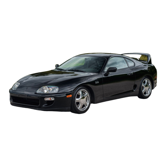
- Page 2 As Toyota’s high–performance flagship car, the Toyota Supra continues to make full use of available advanced technology. In its fourth full model change, the Toyota Supra has been reborn, making great strides in becoming recognized as a full–fledged, world class sports car.
- Page 3 EXTERIOR APPEARANCE...
- Page 4 FOREWORD To assist you in your service activities, this manual explains the main characteristics of the new Toyota Supra, in particular providing a technical explanation of the construction and operation of new mechanisms and new technology used. Applicable models: JZA80 series This manual is divided into 4 sections.
-
Page 5: Model Code
L : Left–Hand Drive V : — ENGINE SPECIFICATION MODEL NAME (7) F : SFI* [EFI] and DOHC A : Toyota Supra Z : SFI [EFI] and DOHC with Turbocharger BODY TYPE DESTINATION (4) L : Liftback (8) A : U.S.A. - Page 6 2. New Model Outline...
- Page 7 MAJOR COMPONENTS The basic components of the new Toyota Supra are as follows. Model Previous Previous Item FR (Front Engine, Drive System Rear Wheel Drive) Type 2JZ–GE: In–line 6, 3.0–Liter 7M–GE: In–Line 6, 3.0–Liter Displacement cm (cu. in.) 2997 (182.9) 2954 (180.3)
- Page 8 DATA LINK CONNECTOR 2 [TOYOTA DIAGNOSTIC COMMUNICATION LINK] The new Toyota Supra has the same DLC2* [TDCL: Toyota Diagnostic Communication Link] as the Camry. The DLC2 has been provided inside the cabin as a connector exclusively for diagnosis of the Engine Control, Transmission Control, ABS, Cruise Control and SRS Airbag to improve serviceability.
- Page 9 ENGINE ENGINE LINE–UP The following are the two newly developed engines that are available for the new Toyota Supra: Engine Max. Output Max. Torque Displace- Features ment Type [SAE–NET] [SAE–NET] An in–line 6, 3.0–liter DOHC engine, adopting ACIS* and dual exhaust man-...
- Page 10 CHASSIS By combining the basic functions of a vehicle, “ to run, to turn, and stop”, at high level, the chassis of the new Toyota Supra aims to realize a ride that is worthy of the world–class sports car. MAJOR COMPONENTS...
-
Page 11: Manual Transmission
CHASSIS . CLUTCH 1. Flywheel Damper The six–speed manual transmission model uses super–long travel flywheel damper made by LUK GmbH (Germany) to reduce the noise and vibration of the drivetrain. A–A Cross Section . MANUAL TRANSMISSION 1. V160 Manual Transmission The 2JZ–GTE engine model adopts a newly developed transmission with six–speed forward gears and a one–speed reverse gear made by GETRAG GmbH (Germany) to ideally match the performance of the engine. - Page 12 BODY By optimally locating the frame components and redesigning their joint structures, the body shell of the new Toyota Supra achieves an ideal rigidity. Also, all panel areas are made seamless by using a single steel sheet, and a newly developed sheet aluminum alloy is adopted for the engine hood and the roof (sports roof model only) for weight reduction.
- Page 13 EXTERIOR STYLING The styling objective of the new Toyota Supra is to produce a high–performance, genuine world–class sports car with an individuality that sets it apart from other sports cars. The styling has the following features: A dynamic composite dimension reminiscent of the firm musculature and physique of a speeding beast.
-
Page 14: Exterior Equipment
EXTERIOR EXTERIOR EQUIPMENT BUMPERS Large, lightweight bumpers that are integrated flush against the body, are used in the front and rear. A front spoiler, integrated with the front bumper, is provided as a standard equipment. A large, lightweight rear spoiler is available as an option for the 2JZ–GTE model. Front Rear LIGHTS... -
Page 15: Rear Lights
EXTERIOR 2. Rear Lights The sporty looking rear combination lights consist of four lenses arranged in–line, each having a separated function. A high–mounted stoplight with Light Emitting Diodes (LED) is embedded in the rear door panel. WIPERS The front wipers consist of the wiper motor and the linkage integrated in its full–floating type pipe frame structure, designed to reduce the noise and irregular wiping angle. - Page 16 Type B NOTICE Your Supra has been fitted with specially developed tires which provide exceptional dynamic performance under general road conditions. However, (on vehicles equipped with the 2JZ–GTE engine,) you may also notice that your tires wear more rapidly than standard tires as a result of their superior performance.
- Page 17 INTERIOR The new Toyota Supra pursues an interior design concept to provide a magnificent space in which a powerful sports–minded form and a superb maneuverability worthy of a high–performance vehicle are incorporated. CABIN The instrument panel and door trim are configured to provide a down–force form to look as if the vehicle is flush against the road surface.
-
Page 18: Front Seat
INTERIOR . SEATS 1. General The bucket type sport seats, with excellent holding capability, are provided for all models. The rear seat is an integrated foldable type. Genuine leather seats are available as an option for all models. The vehicles destined for Canada are also available with seat heaters on their genuine leather seats. -
Page 19: Rear Seat
INTERIOR The seatpad of the seatback is constructed of two layers as illustrated below. The soft surface comes in contact with the occupant, while the hard chip–urethane inside supports the occupant when the vehicle makes a turn. Previous 3. Rear Seat A rear seat with an integrated folding seatback is used. -
Page 20: Seat Belts
INTERIOR . SEAT BELTS The front seats are provided with the 3–point ELR (Emergency Locking Retractor) seat belts with an electronically operated tension reduction mechanism as standard equipment. The passenger seat is additionally provided with an ALR ( Auto–Locking Retractor) mechanism. The front seat belt inner buckle is attached to the seat adjuster. - Page 21 INTERIOR 2. Ceiling Area A molded type roof headlining used. The front and rear roof side inner garnishes have been integrated for a more attractive appearance. A spring mechanism has been provided in the sun visor holder to improve its operability. The inner rear view mirror is attached to the inside of the front windshield.
-
Page 22: Tonneau Cover
INTERIOR . TONNEAU COVER A lightweight tonneau cover is used. . FLOOR CARPET The floor carpet is one piece from the front to the rear. The floor carpet is filled with urethane on the underside. This not only gives the surface a flat structure but also improves noise damping. A–A ’... - Page 23 INSTRUMENT PANEL, SWITCH LAYOUT AND EQUIPMENT The instrument panel of the new Toyota Supra maintains design continuity with the center console, and it wraps the driver with its large–curve cockpit design. All the instruments are enclosed in an instrument cluster featuring a new glare–proof and soft–to–the–touch finish.
-
Page 24: Combination Meter
INTERIOR . COMBINATION METER The three sporty looking, large instruments are arranged side by side for good visibility. A cableless, electric speedometer is used. In addition, an electronic odo/trip meter, which is separate from the speedometer, is used. A master warning lamp for the various warning lamps is newly equipped in the tachometer. A shift position indicator is provided in the tachometer for the automatic transmission model only. -
Page 25: Audio System
INTERIOR The defroster performance is enhanced through the adoption of radial–flow type front defroster nozzles that produce a smooth airflow, as well as the enlarged opening of the driver side defroster nozzle. Previous . AUDIO SYSTEM An AM–FM multiplex ETR (Electronic Tuning Radio) with cassette deck is standard, and a CD (Compact Disc) player is an option. - Page 26 INTERIOR Layout of SpeakersA . IGNITION KEY CYLINDER The ignition key cylinder has been relocated from the side of the steering column to the instrument panel for easier operation. Previous The previous button type ignition key cylinder has been replaced with a push–in type. The ignition key is simply pushed in first to turn it from the ACC to LOCK position.
-
Page 27: Safety And Environment
SAFETY AND ENVIRONMENT . STEERING WHEEL All models use a four–spoke type ϕ370mm steering wheel covered with genuine leather. . TILT STEERING A tilt steering is standard for all models. When the tilt lever is turned up, the steering wheel moves to the highest position to provide space for easier entry and exit. -
Page 28: Cruise Control System
INTERIOR AIRBAG In addition to the standard driver’s airbag in the steering pad, the new Toyota Supra offers a front passenger airbag located in the instrument panel above the glove box. . CRUISE CONTROL SYSTEM The cruise control system is standard equipment The main switch and control switch are on the one lever, which is installed on the steering column and can be operated easily. -
Page 29: Theft Deterrent System
INTERIOR . POWER WINDOW SYSTEM A power window system is standard equipment The power window system includes one–touch auto down. The one–touch auto down function automatically opens the driver’s side window fully. Driver Side . DOOR LOCK CONTROL SYSTEM The door lock control system with 2–step unlock function is standard equipmen. -
Page 30: Illuminated Entry System
An illuminated entry system is standard equipment in all models. This system makes it easy to enter and exit the new Toyota Supra at night, etc. The illuminated entry entry system turns on the dome light and the door key and ignition key illumination lights for 15 seconds after either door is closed when passengers are entering or leaving the vehicle. - Page 31 SAFETY AND WEIGHT REDUCTION A number of safety features are used in consideration of high performance engine and high speed driving capability. After due consideration for safety, a detailed weight reduction effort has been able to realize the vehicle’s full potential.
- Page 32 3. Technical Description...
- Page 33 ENGINE — 2JZ–GE ENGINE ENGINE 2JZ–GE ENGINE . DESCRIPTION The 2JZ–GE engine, which is newly–developed in place of the previous 7M–GE engine, is an in–line 6, 3.0 liter, 24–valve DOHC engine designed to run best at medium to high speeds. With such features as a higher compression ratio, ACIS* (Acoustic Control Induction System) and dual exhaust manifolds, all contributing to a higher intake and exhaust efficiency, this engine provides both high power output and high fuel efficiency at high levels.
- Page 34 ENGINE — 2JZ–GE ENGINE . ENGINE SPECIFICATIONS AND PERFORMANCE CURVE Engine 2JZ GE 2JZ–GE 7M GE 7M–GE Item No. of Cyls. & Arrangement 6–Cylinder, In–Line 24–Valve DOHC, Valve Mechanism Belt Drive Combustion Chamber Pentroof Type Manifold Cross–Flow Fuel System SFI* [EFI] MFI* [EFI]...
- Page 35 ENGINE — 2JZ–GE ENGINE . FEATURES OF 2JZ–GE ENGINE Features of the 2JZ–GE engine are listed below. Features Contents A pentroof type combustion chamber plus high compression ratio. A valve angle carefully determined to ensure best results in medium and high speeds. A large valve diameter plus a high valve lift.
-
Page 36: Cylinder Head Cover
ENGINE — 2JZ–GE ENGINE ENGINE PROPER 1. Cylinder Head Cover A 3–part type cylinder head cover is used. No. 1 and No. 2 cylinder head covers are made of magnesium to reduce weight. The cylinder head cover gaskets used are made of acrylic rubber with a superior heat resistance capacity. -
Page 37: Cylinder Head
ENGINE — 2JZ–GE ENGINE 2. Cylinder Head The cylinder head is made of an aluminum alloy having good thermal conductivity. The combustion chamber is a 4–valve pentroof type with the valve angle at 45 degrees. The spark plugs are located at the near center of the combustion chamber to increase anti–knocking performance and combustion efficiency. -
Page 38: Cylinder Head Gasket
ENGINE — 2JZ–GE ENGINE 3. Cylinder Head Gasket A single–layered metal gasket provides good sealing performance and durability. A—A’ Cross Section 4. Cylinder Block The cylinder block is made of cast iron having a skeleton structure consisting of 11 oil return and blow–by gas passages and 2 main oil holes. - Page 39 ENGINE — 2JZ–GE ENGINE 5. Piston Pistons are made of aluminum alloy having outstanding high–temperature strength. Slotless type oil return holes are provided in the oil ring grooves to lower the temperature in the top ring groove, thereby enhancing the engine’s reliability. The piston skirt area has been coated with resin for decreased friction characteristics.
-
Page 40: Crankshaft Pulley
ENGINE — 2JZ–GE ENGINE 7. Crankshaft The crankshaft has seven journals and twelve counterweights. The pins and journals are induction–hardened to increase rigidity thereby reducing vibration and noise. Aluminum alloy bearings are used to improve wear resistance; and to reduce noise, no oil groove is provided in the cap side bearings. - Page 41 ENGINE — 2JZ–GE ENGINE . VALVE MECHANISM 1. General Each cylinder is equipped with two intake valves and two exhaust valves. Intake and exhaust efficiency has been increased due to the larger total port areas. The valves are directly opened and closed by two belt–driven camshafts. 2.
- Page 42 ENGINE — 2JZ–GE ENGINE 3. Intake and Exhaust Valves The intake and exhaust valves are made of heat resistant steel. Also, through the application of the soft nitriding process to the valve stem, and cobalt alloy binding to the valve face, as shown, valves have been...
-
Page 43: Timing Belt
ENGINE — 2JZ–GE ENGINE 5. Timing Belt The timing belt has high heat resistance and durability. The tooth profile of the timing belt is shown in the illustration below. This design ensures a quiet operation and high–load transmission. The automatic tensioner is made up of a spring and oil damper, and maintains proper timing belt tension at all times. - Page 44 ENGINE — 2JZ–GE ENGINE LUBRICATION SYSTEM 1. General The lubrication is fully pressurized and all oil passes through an oil filter The oil pump is a trochoid gear type and is directly driven by the crankshaft.
-
Page 45: Oil Pan
ENGINE — 2JZ–GE ENGINE 2. Oil Pan The oil pan is made up of two pieces. No. 1 oil pan is made of aluminum alloy and No. 2 oil pan is made of steel. The No. 1 oil pan section is secured to the cylinder block and transmission housing, increasing rigidity. Partitions in the form of ribs have been provided in the No 1 oil pan to improve strength of the oil pan and to provide smoother flow of oil returning from the cylinder block. -
Page 46: Cooling System
ENGINE — 2JZ–GE ENGINE COOLING SYSTEM 1. General The cooling system is of the pressurized, forced–circulation type. A thermostat with a bypass valve is located on the water pump inlet side of the cooling circuit. As the coolant temperature rises, the thermostat opens and the bypass valve closes, so the system maintains suitable temperature distribution in the cylinder head. -
Page 47: Water Pump
The automatic transmission model is equipped with an automatic transmission fluid oil cooler in the lower tank, as in the previous model. However, as the Toyota Supra with 7M–GTE engine from the ’90 model year did, the new 2JZ–GE engine model uses twin–tube type oil cooler with inner fins in place of the four–stage multiplate type oil cooler used in the previous 7M–GE engine model. -
Page 48: Air Cleaner
ENGINE — 2JZ–GE ENGINE . INTAKE AND EXHAUST SYSTEM 1. Air Cleaner The large–capacity air cleaner is used in the new Toyota Supra. An element cap is attached to the air cleaner case to increase ease of servicing. 2. Throttle Body... - Page 49 The construction and operation of the IAC* valve [ISC* valve] in the 2JZ–GE engine are basically the same as those of the 7M–GE engine on the previous Toyota Supra. However, the California specification models use their own IAC* valve [ISC* valve] in conjunction with the adoption of the Air Assist System.
-
Page 50: Exhaust Manifold
ENGINE — 2JZ–GE ENGINE 5. Exhaust Manifold The exhaust manifold is made up of 2 parts, No. 1 and No. 2, to reduce exhaust gas interference and thereby improve the engine performance. They are fitted via a stainless steel gaskets having a laminated structure to increase sealing performance. -
Page 51: Exhaust Pipe
ENGINE — 2JZ–GE ENGINE 6. Exhaust Pipe The exhaust pipes are made of stainless steel. The catalytic converters are monolithic type three–way catalytic converters. The center exhaust pipe separates into a “Y” in the middle, and each pipe after the “Y” is provided with its own muffler. -
Page 52: Fuel System
1. General The fuel system of the 2JZ–GE engine is basically the same as that of the 7M–GE engine used on the previous Toyota Supra. However, it has undergone the changes listed below, including a plastic fuel tank, and, for the California specification models, the adoption of the Air Assist System. -
Page 53: Fuel Injector
2. Air Assist System This system was adopted to the 3VZ–FE engine for the ’92 Camry, but it has also been adopted for the new Toyota Supra to reduce HC emissions. This system directs part of the air which bypasses the throttle valve to the injection port of the fuel injector. -
Page 54: Fuel Tank
The serviceability of the fuel tank, fuel pump, and fuel sender gauge has been improved by providing a service hole in the luggage compartment. IGNITION SYSTEM The ignition system in the 2JZ–GE engine is basically the same as that in the 7M–GE engine for the previous Toyota Supra. -
Page 55: Automatic Tensioner
ENGINE — 2JZ–GE ENGINE . SERPENTINE BELT DRIVE SYSTEM 1. General Accessory components are driven by a ser– pentine belt consisting of a single V–ribbed belt. It reduces the overall engine length, weight and number of engine parts. An automatic tensioner eliminates the need for tension adjustment. -
Page 56: Engine Mounting
. ENGINE MOUNTING In the new Toyota Supra, the engine is supported by liquid filled compound mounts fitted on both sides of the engine to reduce vibration and noise at all speeds as same as the previous model. Aluminum engine brackets also reduce engine vibration and noise while minimizing the total engine weight. - Page 57 1. General The engine control system of the 2JZ–GE engine is basically the same in construction and operation as that of the 7M–GE engine for the previous Toyota Supra. However, in automatic transmission models, the ECM* [engine ECU] and PCM*...
- Page 58 ENGINE — 2JZ–GE ENGINE System Outline 2JZ–GE 7M–GE Fuel Pump Control Under light engine loads, pump speed is low to reduce . Page 67 electric power loss. Fuel Pressure Control In hot engine conditions, the fuel pressure is increased to —...
- Page 59 ENGINE — 2JZ–GE ENGINE 2. Construction The configuration of the engine control system which can be broadly divided into three groups: the ECM [engine ECU], the sensors and the actuators is shown in the following chart. Shaded portions are different from the 7M–GE engine for the previous models.
- Page 60 The following list summarizes each system and control item of the 2JZ–GE engine, including related sensors, ECM [ECU] and others. Shaded portions are different from the 7M–GE engine for the previous Toyota Supra. : Applicable only to California specification models.
- Page 61 ENGINE — 2JZ–GE ENGINE 4. Engine Control System Diagram : ’Main Heated Oxygen Sensor” for California specification models. : Applicable only to California specification models. : Applicable only to automatic transmission models.
- Page 62 ENGINE — 2JZ–GE ENGINE 5. Layout of Components...
- Page 63 This is basically the same as that used in the 7M–GTE engine for the previous Toyota Supra. For details, see page 85 in 1987 model New Car Features (Pub. No. NCF013U).
- Page 64 L–type MFI (Multiport Fuel Injection) [EFI] system with a vane type volume air flow meter used in the 7M–GE engine of the pervious Toyota Supra. The following are the main differences of the fuel injection system in the new 2JZ–GE engine, as compared to the previous 7M–GE engine:...
- Page 65 ENGINE — 2JZ–GE ENGINE 8. ESA (Electronic Spark Advance) General The ESA system of the 2JZ–GE engine differs from the system of the 7M–GE engine in the following areas: In the 2JZ–GE engine, 2 knock sensors are used to further improve knock detection. In addition, torque control correction has been added to ignition timing control in automatic transmission models.
- Page 66 ENGINE — 2JZ–GE ENGINE Igniter Control In the 2JZ–GE engine, the ECM [engine ECU] outputs the IGT signal based on the primary current energizing time it has calculated. 1) Calculation of Primary Current Energizing Time In order to control primary current energizing start time via the IGT signal, the ECM of the 2JZ–GE engine calculates the primary current energizing time according to the following formula: Energizing Time = Energizing Time for Battery Voltage * Correction for Engine Speed...
- Page 67 ENGINE — 2JZ–GE ENGINE 2) Ignition Timing Signal (IGT Signal) When the ignition timing is set 10° BTDC (initial ignition timing; IDL signal ON, terminals TE and E in DLC1 or 2* connected), the OFF point of the subsequent NE signal after the G2 (or G1) signal falls on 5° BTDC for the No.
- Page 68 ENGINE — 2JZ–GE ENGINE 9. IAC (Idle Air Control) [ISC] In the IAC [ISC] system of the 2JZ–GE engine, as same as the previous 7M–GE engine, the step motor type IAC [ISC] valve is used, and the ECM* [engine ECU] controls the idle speed at a target speed based on the signals from the various sensors by adjusting the volume of air bypassing the throttle valve.
- Page 69 This increases the power output in all ranges from low to high speeds. This system is basically the same as the Intake Air Control System of the 7M–GE engine for the previous Toyota Supra.
- Page 70 ENGINE — 2JZ–GE ENGINE 12.Fuel Pressure Control When starting engine at high temperature, the ECM [ECU] turns on a VSV to draw atmospheric pressure into the diaphragm chamber of the pressure regulator. There by the fuel pressure is increased to prevent fuel vapor lock in order to help engine start.
- Page 71 ENGINE — 2JZ–GE ENGINE 14.Air Conditioning Control General To maintain drivability and prevent idle speed from dropping, the 2JZ–GE engine adopted a function which temporarily retards or cuts off the air conditioning operation according to the engine condition. Air Conditioning Compressor Delay Control When the ECM [engine ECU] detects a signal (A/C) from the air conditioning ECU that the air conditioning switch is turned on, the ECM outputs a magnet clutch signal (ACMG) to the magnet clutch relay and turns it on.
- Page 72 ENGINE — 2JZ–GE ENGINE 15.Evaporative Emission Control General The evaporative emission control is a system which utilizes the intake manifold vacuum to draw the evaporative emissions into the intake air chamber and mix them in with the intake air. The 2JZ–GE engine has adopted a duty–cycle type VSV (Vacuum Switching Valve) controlled by the ECM [engine ECU] to purge the evaporative emissions from the charcoal canister.
- Page 73 The 2JZ–GE engine adopts two mode functions, the normal and test modes, in its diagnostic system. While the normal mode offers the same detecting functions as those of the 7M–GE engine of the previous Toyota Supra, the test mode can detect malfunctions, such as poor contact between terminals or a momentary wire disconnection, two symptoms that are difficult to detect in the normal mode.
- Page 74 ENGINE — 2JZ–GE ENGINE Malfunction Malfunction Indicator Lamp* Code Code Item Item Diagnosis Diagnosis Stored in Stored in Normal Test Memory Mode Mode (1) Main oxygen sensor voltage is 0.45 V or less (lean) for 90 sec. under conditions (a) and (b). (a) Coolant temp: 70°C (158°F) or more.
- Page 75 ENGINE — 2JZ–GE ENGINE Malfunction Malfunction Indicator Lamp* Code Code Item Item Diagnosis Diagnosis Stored in Stored in Normal Test Memory Mode Mode All conditions below are detected continuously for 8 sec. or more. No. 1 Vehicle (a) Vehicle speed signal: 0 pulses Speed Sensor (b) Engine speed: 3000 rpm or more Signal...
-
Page 76: Fail Safe
ENGINE — 2JZ–GE ENGINE 17.Fail Safe As in the 7M–GE engine for the previous Toyota Supra, the 2JZ–GE engine has a fail–safe function and back–up function. The basical function and operation are the same as in the 7M–GE engines. Fail–Safe Function The following table compares the fail safe function of the 2JZ–GE and 7M–GE engines. - Page 77 ENGINE — 2JZ–GE ENGINE EMISSION CONTROL SYSTEM 1. System Purpose System Abbreviation Purpose Positive crankcase ventilation Reduces blow–by gas (HC) Evaporative emission control EVAP Reduces evaporative HC Exhaust gas recirculation Reduces NOx Three–way catalytic converter Reduces HC, CO and NOx Sequential multiport fuel injection SFI [EFI] Regulates all engine conditions for...
- Page 78 ENGINE — 2JZ–GTE ENGINE 2JZ–GTE ENGINE DESCRIPTION An inline 6–cylinder, 3.0–liter, 24–valve DOHC engine with twin turbochargers and charge air cooler [intercooler], the 2JZ–GTE engine is a newly developed engine which replaces the previous 7M–GTE engine. By using two turbochargers, this Two–Way Twin Turbo System offers both superior power output and responsiveness. Furthermore, this engine adopts the DIS (Direct Ignition System) which discontinues the use of distributor and high–tension cords for an efficient secondary current delivery to the spark plugs.
- Page 79 ENGINE — 2JZ–GTE ENGINE ENGINE SPECIFICATIONS AND PERFORMANCE CURVE Engine 2JZ GTE 2JZ–GTE 7M GTE 7M–GTE Item No. of Cyls. & Arrangement 6–Cylinder, In–Line 24–Valve DOHC, Valve Mechanism Belt Drive Combustion Chamber Pentroof Type Manifold Cross–Flow Fuel System SFI* [EFI] MFI* [EFI] Displacement...
- Page 80 ENGINE — 2JZ–GTE ENGINE FEATURES OF 2JZ–GTE ENGINE Features of the 2JZ–GTE engine are as listed below. Features Contents The Two–Way Twin–Turbo System, in which two small turbochargers are used, offers high power output and response. The DIS (Direct Ignition System) contributes to the high powerful output by providing a powerful spark to the engine.
- Page 81 ENGINE — 2JZ–GTE ENGINE ENGINE PROPER 1. Cylinder Head Cover A 2–part type aluminum cylinder head cover is used. The cylinder head cover gaskets are made of acrylic rubber with superior heat resistance. The floating rubber washers used in fastening the cylinder head covers to the cylinder head allow the covers to float and helps to reduce noise.
- Page 82 ENGINE — 2JZ–GTE ENGINE 3. Cylinder Head Gasket A 4–layer metal gasket with a superior durability is used for the cylinder head gasket. In addition, formed beads are applied onto the two outer stainless steel plates to improve the gasket’s sealing ability. A—A’...
- Page 83 ENGINE — 2JZ–GTE ENGINE . VALVE MECHANISM 1. General The valve mechanism of the 2JZ–GTE engine is basically the same as that of the 2JZ–GE engine. However, the valve timing and valve lift specifications have been revised to best suit the 2JZ–GTE engine. In conjunction with the use of the DIS (Direct Ignition System), the intake camshaft is provided with timing rotors to trigger the camshaft position sensors.
-
Page 84: Lubrication System
ENGINE — 2JZ–GTE ENGINE LUBRICATION SYSTEM 1. General The lubrication system in the 2JZ–GTE engine is basically the same as that of the 2JZ–GE engine. However, a water–cooled oil cooler is equipped in the 2JZ–GTE engine to cool the engine oil, and oil jets are provided in the cylinder block to cool the pistons. -
Page 85: Oil Cooler
ENGINE — 2JZ–GTE ENGINE 2. Oil Cooler The 2JZ–GTE engine is equipped with a water–cooled, multi–plate, full–flow type oil cooler between the oil filter and oil filter bracket, to cool the engine oil. The oil filter bracket is made of a lightweight magnesium alloy. Oil Cooler Cross Section 3. - Page 86 ENGINE — 2JZ–GTE ENGINE COOLING SYSTEM 1. General The 2JZ–GTE engine cooling system is the same pressurized, forced–circulation type as that used in the 2JZ–GE engine. In order to optimally match the high performance of the 2JZ–GTE engine with its Two–Way Twin Turbo System, a cooling circuit has been provided for the turbochargers as well as for the engine oil cooler.
- Page 87 ENGINE — 2JZ–GTE ENGINE . INTAKE AND EXHAUST SYSTEM 1. Air Cleaner The 2JZ–GTE engine is equipped with the same large–capacity air cleaner adopted in the 2JZ–GE engine, with a filter element cap provided on the air cleaner case for ease of servicing. 2.
- Page 88 ENGINE — 2JZ–GTE ENGINE 4. Exhaust Manifold The exhaust manifolds are made of heat–resistant cast steel with superior heat–resisting and acid–resisting capacities. The exhaust manifolds are separated into two parts, each part handling three cylinders grouped 1, 2, 3, and 4, 5, 6. The exhaust pressure transmission efficiency is improved in this manner by having each exhaust manifold direct the exhaust gas flow to each of the turbochargers.
- Page 89 ENGINE — 2JZ–GTE ENGINE 5. Exhaust Pipe The exhaust pipe for the 2JZ–GTE engine is the same stainless steel type used for the 2JZ–GE engine. Also, monolithic type, three–way catalytic converters containing metallic substrate are used in this exhaust system. The exhaust pipe outputs an exhaust sound to match the vehicle’s sporty image.
-
Page 90: Turbocharger System
ENGINE — 2JZ–GTE ENGINE . TURBOCHARGER SYSTEM 1. General In the place of the single turbocharger system used in the 7M–GTE engine, the 2JZ–GTE engine adopts the Two–Way Twin Turbo System which uses two turbochargers. Under this system, the two compact turbochargers provide separate functions according to the engine running condition. - Page 91 ENGINE — 2JZ–GTE ENGINE 2. Components of Turbocharger System Twin Turbochargers As illustrated below, the 2JZ–GTE engine is equipped with two lightweight and compact turbochargers placed parallel to the line of flow from the intake to exhaust. The twin–turbocharger assembly consists of the No. 1 turbocharger, No. 2 turbocharger, and turbine outlet elbow, as illustrated below.
- Page 92 ENGINE — 2JZ–GTE ENGINE 1) Turbocharger Housing Each of the turbochargers can be broadly divided in the following three housings: compressor, bearing and turbine housings. The compressor housing is made of cast aluminum alloy, and the turbine housing of highly heat–resistant steel. The bearing housing is made of gray cast steel, in which compact and lightweight impeller and turbine wheels are enclosed.
- Page 93 ENGINE — 2JZ–GTE ENGINE Charge Air Cooler [Intercooler] This turbocharger system adopts an air–cooled, tube type charge air cooler [intercooler] located in the front part of the right front wheel housing. Large–diameter air tubes and hoses are used to accommodate large airflow and reduce its pressure loss. The charge air cooler [intercooler] tank and air tubes are made lightweight using plastic.
- Page 94 ENGINE — 2JZ–GTE ENGINE Control Valves There is a total of six control valves used in the Two–Way Twin Turbo System. The details of these valves are as follows. Valve Operation Intake Air Located downstream of the No. 2 turbocharger intake airflow, during No. 2 turbocharger start/ Control Valve stop operation it permits or stops the flow of intake air through the No.
- Page 95 ENGINE — 2JZ–GTE ENGINE Operation of Single Turbocharging Since the actuators for the intake air control valve and exhaust gas control valve are inactive during low engine rpm operation, these valves remain closed. The waste gate valve is also closed, and only the No. 1 turbocharger will provide the boost pressure. When the intake air turbocharging pressure downstream from the No.
- Page 96 ENGINE — 2JZ–GTE ENGINE Single Turbocharging and Twin Turbocharging Operations When the engine operation passes from the low–rpm to the high–rpm region, at first the exhaust gas control valve opens, and this is followed by the opening of the intake air control valve. When the exhaust gas control valve opens, it causes the No.
- Page 97 ENGINE — 2JZ–GTE ENGINE Operation of Twin Turbocharging The exhaust gas control valve and intake air control valve are open, allowing the No. 1 and No. 2 turbochargers to boost. At this time, even if the exhaust bypass valve operates, it cannot effect any boost pressure control, since it is located downstream of the No.
- Page 98 ENGINE — 2JZ–GTE ENGINE 3. Jet Pump System After the fuel pressurized by the fuel pump reaches the injectors, any unused fuel returns to the fuel tank. The fuel tank is provided with a sub–tank which prevents the fuel from sloshing. This is to prevent the fuel supply from being disrupted, or the fuel tank from generating a noise during sudden brake applications or rough–road driving.
-
Page 99: Ignition System
ENGINE — 2JZ–GTE ENGINE IGNITION SYSTEM 1. General In place of the DLI (Distributor–Less Ignition) system used in the 7M–GTE engine, the DIS (Direct Ignition System) is newly adopted in the 2JZ–GTE engine. While both systems do not use a distributor, the DIS differs from the DLI in the following areas: There are six ignition coils provided, and each of the coils fits over each spark plug. -
Page 100: Ignition Coils
ENGINE — 2JZ–GTE ENGINE 2. Igniter The internal system diagram of the igniter is shown below. A characteristic of this igniter is that it contains the 6 power transistors as illustrated. Based on the IGT signals input for each cylinder, the drive circuit activates the respective power transistors to control the primary ignition signals (IGC) for all cylinder. - Page 101 ENGINE — 2JZ–GTE ENGINE . SERPENTINE BELT DRIVE SYSTEM The serpentine belt drive system of the 2JZ–GTE engine is basically the same as that of the 2JZ–GE engine. However, along with the adoption of the flywheel damper, the 2JZ–GTE engine with the manual transmission is provided with a belt tensioner absorber which prevents the belt from vibrating or whining during a sudden engine rpm...
- Page 102 The engine control system of the 2JZ–GTE engine is basically the same in construction and operation as that of the 7M–GTE engine for the previous Toyota Supra. However, as in the 2JZ–GE engine, the sequential multiport fuel injection system is adopted, and the ECM*...
- Page 103 ENGINE — 2JZ–GTE ENGINE System Outline 2JZ–GTE 7M–GTE Fuel Pressure In hot engine conditions, the fuel pressure is increased to Control improve restartability. . Page 115 Oxygen Sensor Maintains the temperature of the oxygen sensor at an Heater Control appropriate level to increase accuracy of detection of the oxygen concentration in the exhaust gas.
- Page 104 ENGINE — 2JZ–GTE ENGINE 2. Construction The configuration of the engine control system which can be broadly divided into three groups: the ECM* [engine ECU], the sensors and the actuators is shown in the following chart. Shaded portions are different from the 7M–GTE engine for the previous models. * : ECM (Engine Control Module)
- Page 105 ENGINE — 2JZ–GTE ENGINE 3. Summary of Engine Control System The following list summarizes each system and control item of the 2JZ–GTE engine, including related sensors, ECM [engine ECU] and others. Shaded portions are different from the 7M–GTE engine.
- Page 106 ENGINE — 2JZ–GTE ENGINE 4. Engine Control System Diagram...
- Page 107 ENGINE — 2JZ–GTE ENGINE 5. Layout of Components...
- Page 108 ENGINE — 2JZ–GTE ENGINE 6. Main Components of Engine Control System General The following table compares the main components of the 2JZ–GTE engine and 7M–GTE engine. Engine 2JZ GTE 2JZ–GTE 7M GTE 7M–GTE Components Mass Air Flow Meter Hot–Wire Type —...
- Page 109 ENGINE — 2JZ–GTE ENGINE 2) Principle When the hot wire is placed in a constant gaseous current, the hot wire temperature varies in accordance with the amount of the air mass flow. If the temperature difference between the hot wire and air mass at the time is “...
- Page 110 ENGINE — 2JZ–GTE ENGINE Camshaft Position Sensors (G and G Signals) The camshaft position sensors consist of a magnet, coil and iron core, and are mounted onto the intake side of the cylinder head. The timing rotor is integrated with the intake side camshaft. Each time the camshaft rotates, the air gap between the pickup coil and the protrusion integrated onto the camshaft is varied.
- Page 111 ENGINE — 2JZ–GTE ENGINE Crankshaft Position Sensor (NE Signal) The crankshaft position sensor consists of a magnet, coil and iron core, and is mounted onto the right side of the oil pump body as illustrated below. The timing rotor is installed on the guide area of the crankshaft timing pulley. The timing rotor attached to the crankshaft has 12 teeth, enabling the pickup coil to produce 12 pulses per each revolution of the crankshaft.
- Page 112 ENGINE — 2JZ–GTE ENGINE 7. SFI (Sequential Multiport Fuel Injection) [EFI] In place of the L–type MFI (Multiport Fuel Injection) [EFI] system with an optical Karman–Vortex type volume air flow meter used in the 7M–GTE engine, the 2JZ–GTE engine uses the L–type SFI [EFI] system with a hot–wire type mass air flow meter.
- Page 113 ENGINE — 2JZ–GTE ENGINE 8. ESA (Electronic Spark Advance) The ESA system of the 2JZ–GTE engine is basically the same in construction and operation as that of the 2JZ–GE engine. However, in the 2JZ–GTE engine, the output method of the ignition trigger signal (IGT) from the ECM* [Engine ECU] to the igniter has been changed to reflect the adoption of the DIS (Direct Ignition System).
- Page 114 ENGINE — 2JZ–GTE ENGINE 9. IAC (Idler Air Control) [ISC] The IAC [ISC] system of the 2JZ–GTE engine is basically the same in construction and operation as that of the 2JZ–GE engine. See 2JZ–GE engine section on page 66. 10.Turbocharger Control The Two–Way Twin Turbo System is equipped with an ECM* [engine ECU] to control the start and stop operation of the No.
- Page 115 ENGINE — 2JZ–GTE ENGINE Control VSV In this system, there are four VSVs provided in the pressurized air circuit for the actuators which operate the valves. By controlling these VSVs, the ECM [engine ECU] can control the operation of the No. 2 turbocharger and the boost pressure of the entire system.
- Page 116 ENGINE — 2JZ–GTE ENGINE ECM [ECU] Function 1) Exhaust Gas Control Valve Control RELEVANT SIGNALS When the engine is accelerated from a speed of approximately 3,000 to 4,000 rpm, the ECM Engine speed (NE) [ECU] turns the VSV2 ON to open the exhaust gas control valve, in accordance with the Throttle position (VTA) degree of the acceleration.
- Page 117 The diagnostic items are basically the same as those on the 2JZ–GE engine. However, code numbers 34, 35, and 47 have been added in conjunction with the adoption of the Two–Way Twin Turbo and the TRAC (Traction Control) systems. For details on the diagnostic items, see ’93 Toyota Supra Repair Manual (Pub. No. RM343U1). 17.Fail–Safe The 2JZ–GTE engine also offers the same fail–safe and back–up functions as in the 2JZ–GE engine.
- Page 118 ENGINE — 2JZ–GTE ENGINE EMISSION CONTROL SYSTEM 1. System Purpose System Abbreviation Purpose Positive crankcase ventilation Reduces blow–by gas (HC) Evaporative emission control EVAP Reduces evaporative HC Exhaust gas Recirculation Reduces NOx Three–way catalytic converter Reduces HC, CO and NOx Sequential multiport fuel injection SFI [EFI] Regulates all engine conditions for...
-
Page 119: Clutch Pedal
CHASSIS—CLUTCH CLUTCH PEDAL . DESCRIPTION The new model’s hydraulic a single–plate clutch is the same as that used in the previous model. The 2JZ–GE engine model uses a push–type clutch cover with the same basic construction and operation as those of the previous 7M–GE engine model. -
Page 120: Clutch Cover
CHASSIS—CLUTCH . CLUTCH COVER The 2JZ–GE engine model uses the same push–type clutch cover as that used in the previous 7M–GE engine model. Although its basic construction and operation are the same as those of the previous model, the pull–type clutch cover for the 2JZ–GTE engine is now made of steel plate instead of cast iron. - Page 121 CHASSIS—CLUTCH . FLYWHEEL DAMPER 1. General The 2JZ–GTE engine model uses a super–long travel type flywheel damper. It contains a decoupling mechanism, consisting of springs, which divides the flywheel into the engine and transmission sections. decreasing fluctuation of torque transmitted from the engine to the transmission, these springs contribute in reducing drivetrain vibration and noise.
-
Page 122: Master Cylinder
For troubleshooting and diagnosis procedures, refer to the ’93 Toyota Supra Repair Manual (Pub. No. RM343U2). In case a defect or wear is found on the secondary flywheel clutch disc friction surface, replace the flywheel damper as a unit, instead of attempting to machine it. - Page 123 CHASSIS—CLUTCH . RELEASE CYLINDER The non–adjustable release cylinder used is the same type used in the previous model. Although its basic construction and operation are the same as those of the previous model, the body of the release cylinder for the 2JZ–GTE engine model is now made of aluminum to reduce weight.
- Page 124 CHASSIS—CLUTCH 2. Turnover Mechanism Construction The turnover mechanism consists of a clutch pedal, assist spring, initial assist spring, and a collar. The ends of the assist spring are attached to the clutch pedal and collar, respectively, and the spring applies constant outward pressure.
- Page 125 CHASSIS—CLUTCH 2) Initial Assist Spring Application When the clutch pedal is not being depressed, the force of the initial assist spring, by way of collar, applies a counterclockwise rotational force onto the front of the assist spring. In addition, the assist spring applies a clockwise rotational force onto the clutch pedal.
- Page 126 High–performance ATF Type T–II is used. — ECM (Engine Control Module) TCM (Transmission Control Module) In order to differentiate these 2 systems, at Toyota, the latter is called “Electronically Controlled Transmission with an Intelligent Sporty Control”. For 2JZ–GTE Engine Model...
- Page 127 CHASSIS — A340E AUTOMATIC TRANSMISSION SpecificationsA Model Previous Transmission Type A340E A340E A340E A340E Engine Type 2JZ GE 2JZ–GE 2JZ GTE 2JZ–GTE 7M GE 7M–GE 7M GTE 7M–GTE Item 2.804 1.531 1.000 Gear Ratio 4th (Overdrive) 0.705 Reverse 2.393 Fluid Capacity 7.2 (7.6, 6.3) 8.2 (8.7, 7.2) 7.2 (7.6, 6.3)
- Page 128 CHASSIS — A340E AUTOMATIC TRANSMISSION HYDRAULIC CONTROL SYSTEM Along with the adoption of the new electronically controlled transmission system, the valve body (which controls the hydraulic pressure) in the A340E automatic transmission for the 2JZ–GTE engine has been modified. However, the A340E automatic transmission for the 2JZ–GE engine remains basically the same as the A340E of the previous model.
- Page 129 CHASSIS — A340E AUTOMATIC TRANSMISSION 2) Construction The following illustration shows the valve layout in the upper and lower valve bodies: Upper Valve BodyA Lower Valve BodyA...
-
Page 130: Chassis — A340E Automatic Transmission
CHASSIS — A340E AUTOMATIC TRANSMISSION 3) Function The following are the functions of the valves used in the A340E automatic transmission of the 2JZ–GTE engine model and those used in the A340E of the 7M–GTE engine model. Transmission A340E A340E Component Function (For... - Page 131 CHASSIS — A340E AUTOMATIC TRANSMISSION Transmission A340E A340E Component Function (For (For (For (For 2JZ–GTE) 7M–GTE) Lock–Up Controls the pressure differential when the lock–up clutch is (14) — Control Valve switched on and off. No. 1 and No. 2 These valves are turned on or off by the ECM* [Engine ECU] (15) —...
- Page 132 CHASSIS — A340E AUTOMATIC TRANSMISSION . ELECTRONIC CONTROL SYSTEM The consolidation of the TCM* [Transmission ECU] with the ECM* [Engine ECU] has allowed for an integrated engine/transmission control. Within the ECM* [Engine ECU] under this system, engine operating conditions such as the engine speed and throttle valve opening angle, are constantly relayed from the engine control section to the transmission control section.
- Page 133 CHASSIS — A340E AUTOMATIC TRANSMISSION 1. Construction (For 2JZ–GE Engine) The electronic control system can be broadly divided into 3 groups: The sensors, ECM* [Engine ECU], and the actuators. The shaded sections which appear below, denote the areas in which the A340E automatic transmission for the 2JZ–GE engine model differs from the previous A340E.
- Page 134 CHASSIS — A340E AUTOMATIC TRANSMISSION 2. Construction (For 2JZ–GTE Engine) The electronic control system of the A340E for the 2JZ–GTE engine has the same 3 groups also found in the system of the 2JZ–GE engine model. The shaded sections denote the areas in which the new A340E differs from the previous A340E.
- Page 135 CHASSIS — A340E AUTOMATIC TRANSMISSION 3. Wiring Diagram For 2JZ–GTE Engine Model For 2JZ–GE Engine Model ECM (Engine Control Module)
- Page 136 CHASSIS — A340E AUTOMATIC TRANSMISSION 4. Layout of Components...
- Page 137 CHASSIS — A340E AUTOMATIC TRANSMISSION 5. Modification of Main Components General Both types of A340E transmissions, additionally equipped with a kick–down switch and a fluid temperature sensor, have modified versions of the No. 2 vehicle speed sensor and pattern select switch. Furthermore, the A340E for the 2JZ–GTE model has an additional OD direct clutch speed sensor, and a modification and addition of the solenoid valve, along with the adoption of the new electronically controlled transmission system.
- Page 138 CHASSIS — A340E AUTOMATIC TRANSMISSION Kick–down Switch 1) Function The kick–down switch is fitted to the floor panel directly under the accelerator pedal. When the accelerator pedal is depressed beyond the full–throttle opening, the pedal presses and thus turns on the kick–down switch. The accelerator pedal is designed in such a way that a greater pedal effort is necessary to activate the kick–down switch than to depress the pedal to the full–throttle position.
- Page 139 CHASSIS — A340E AUTOMATIC TRANSMISSION a. S Range (Throttle Valve Opening 85% or more, Kick–Down Switch OFF) When the vehicle is running in S range, the gear is shifted to the OD gear when the vehicle reaches the V up speed.
- Page 140 CHASSIS — A340E AUTOMATIC TRANSMISSION No. 2 Vehicle Speed Sensor (Main Sensor) The No. 2 vehicle speed sensor used in both types of the new A340E transmission has been changed from the previous lead–switch type to the pick–up coil type. This sensor consists of a permanent magnet, coil and yoke.
- Page 141 CHASSIS — A340E AUTOMATIC TRANSMISSION Function and Connections of Solenoid ValvesA Solenoid Valve Functions Connections Modulates solenoid pressure into lock–up (A) Solenoid Modulator Valve No. 3 control pressure, according to duty cycle sig- (B) Solenoid Relay Valve nals provided by ECM* [Engine ECU]. (C) Drain Modulates solenoid pressure into accumula- (A) Solenoid Modulator Valve...
- Page 142 CHASSIS — A340E AUTOMATIC TRANSMISSION Function of ECU 1) General The shift and lock–up timing has been changed in connection with the adoption of the manual mode. Moveover, an engine torque control has been added to provide a smooth gear shifting operation. On the 2JZ–GTE engine model, a lock–up pressure control, accumulator back pressure control, and line pressure control have been added to provide smooth shifting characteristics.
- Page 143 CHASSIS — A340E AUTOMATIC TRANSMISSION ii) During High Fluid Temperature Operation In order to prevent an abnormal rise in the fluid temperature, when fluid temperature reaches a high level with the shift lever in “D” and the pattern select switch in manual mode, the ECM* [Engine ECU] changes the shift program from manual to normal mode, even if the pattern select switch remains in the manual mode.
- Page 144 CHASSIS — A340E AUTOMATIC TRANSMISSION 4) Lock–Up Pressure Control Lock–up control is performed by electronically controlling the lock–up control valve which modulates the engagement pressure acting on the lock–up clutch, and lock–up pressure which activates the lock–up relay valve that switches engagement and disengagement of the clutch. As a result, these valves are activated gradually and smooth engagement and disengagement are performed.
- Page 145 CHASSIS — A340E AUTOMATIC TRANSMISSION 6) Line Pressure Control The throttle pressure that is applied to the primary regulator valve (which modulates line pressure) causes the No. 5 solenoid valve, under electronic control, to precisely and minutely modulate and generate line pressure according to the accelerator pedal effort, or engine power output detected.
- Page 146 CHASSIS — A340E AUTOMATIC TRANSMISSION 7) Self–Diagnosis The functions of the self–diagnosis are the same as those of the previous model. However, along with the increase in the number of sensors and solenoid valves, the diagnostic trouble codes have been increased as follows: Diagnosis Trouble CodeA New Added Code No.
- Page 147 The V160 is a newly developed 6–speed transmission of a lightweight and compact design. The reverse gear of this transmission is a constant mesh type, and all gears, including the reverse gear, use synchromesh mechanisms. The transmission oil used is the TOYOTA GEAR OIL V160 or ESSO ATF DEXRON D–21065. All these features contribute in making this transmission dynamic, quiet, and fuel–efficient.
- Page 148 CHASSIS—MANUAL TRANSMISSIONS W58 MANUAL TRANSMISSIONS 1. General The W58 manual transmission of the new model offers the same basic construction and operation as those of the W58 of the previous model. However, it has been made easier to operate by relocating the shift lever and shortening the shift and select strokes.
-
Page 149: Transmission Case
. V160 MANUAL TRANSMISSION 1. General The newly developed V160 is the first Toyota manual transmission with 6 forward speeds. Compact in design, the V160 offers a multi–cone type synchronizer ring in the synchromesh mechanisms of the 1st to 4th gears for improved operability. - Page 150 CHASSIS—MANUAL TRANSMISSIONS 3. Transmission Gear General The V160 manual transmission consists of 3 shaft; input, output, and counter shifts. Power is transmitted from the input shaft to the counter shaft, and then to the output shaft that is coaxially fitted to the input shaft. The input and output shafts mesh directly to each other in 5th gear.
- Page 151 CHASSIS—MANUAL TRANSMISSIONS Reverse A–A’ Cross Seciton...
- Page 152 CHASSIS—MANUAL TRANSMISSIONS 4. Shift and Select Mechanism General The direct control shift and select mechanisms used are similar to those used in the new W58 manual transmission. However, the V160 has 4 shift fork shafts instead of the 3 being used in the W58. The No. 3 shift fork are attached to the No.
- Page 153 CHASSIS—MANUAL TRANSMISSIONS Double–Meshing Prevention Mechanism Instead of preventing the shift lock movement by way of an interlock pin inserted between the shift fork shafts, as the conventional transmissions including the W58 does, the double–meshing prevention mechanism of the V160 prevents the movement of the shift fork shafts by way of the interlock plate attached to the intermediate case. A groove, into which the interlock plate engages, is provided around the circumference of the 3 shift fork shafts and the shift rail.
- Page 154 CHASSIS—MANUAL TRANSMISSIONS 5. Bearings Roller bearings, having a large load capacity, are used at the rear of the output shaft and on the counter shaft. Ball bearings are used at the front of the output shaft. Tapered roller bearings, having a large load capacity, are used at the center of the input and output shafts. The preload of the tapered roller bearings is adjusted by a shim between the ball bearings and the input shaft.
-
Page 155: Shift Lever
CHASSIS—MANUAL TRANSMISSIONS 7. Shift Lever Reverse Mis–Shift Prevention Mechanism The mechanism prevents shifting into reverse unless the shift lock release collar provided on the shift lever is raised. 1) Construction and Operation The reverse mis–shift prevention mechanism consists of a shift lock release collar, release cable, detent sleeve, and a cap. -
Page 156: Propeller Shaft
CHASSIS — PROPELLER SHAFT PROPELLER SHAFT . DESCRIPTION There are 2 separate types of propeller shafts used on the new model, according to the engine model used, either the 2JZ–GE or the 2JZ–GTE. Both of these propeller shafts are 2–part types, each part consisting of a strong tube offering high centering and dimensional precision and a small diameter. - Page 157 CHASSIS—PROPELLER SHAFT FLEXIBLE JOINT No. 3 joint of the propeller shaft is flexible coupling made of rubber having large vibration absorbing effects and good balancing quality.
- Page 158 CHASSIS—DIFFERENTIAL DIFFERENTIAL DESCRIPTION There are 2 types of differential used on the new model, which are also used on the previous model: the conventional, and the LSD (Limited Slip Differential) type. The conventional type differential, which is standard equipment on the 2JZ–GE engine model, is the same 2–pinion type used on the previous model.
- Page 159 CHASSIS—DIFFERENTIAL CONVENTIONAL TYPE DIFFERENTIAL Compared to the conventional differential used on the previous model, the new model offers the following low–noise and highly rigid characteristics: (1) For a quieter operation, the contact ratio of the hypoid gears (the set of drive pinion and ring gear) is increased by increasing the number to teeth and their facewidth.
- Page 160 CHASSIS—DIFFERENTIAL LSD (Limited Slip Differential) TYPE DIFFERENTIAL The LSD type differential has been changed from the previous multi–plate type to the torque sensing type. Its characteristics are as follows: Good traction of high–bias ratio design is obtained through the utilization of the worm gear surface friction and thrust washer friction.
- Page 161 CHASSIS—DIFFERENTIAL DIFFERENTIAL SUPPORT The differential is mounted to the rear sub–frame via 3 rubber mounts for the 2JZ–GE engine model, and via 4 rubber mounts for the 2JZ–GTE engine model. On the 2JZ–GTE engine the rear right mount is a liquid–filled to provide quiet operation.
-
Page 162: Drive Shaft
CHASSIS — DRIVE SHAFT DRIVE SHAFT DESCRIPTION The driveshaft of the previous model consisted of a tripod type CVJ (Constrant–Velocity Joint) used on the differential side, and a Rzeppa type CVJ on the wheel side. However, on the new model, a compact and lightweight cross–groove type CVJ is used on both sides of the drive shaft. - Page 163 CHASSIS—DRIVE SHAFTS CROSS–GROOVE TYPE CONSTANT–VELOCITY JOINT 1. Construction The joint consists of outer and inner races, each with ball grooves, a cage that retains balls, and 6 balls. Ball grooves on the outer race intersect on the inner race. 2. Operation The cross–groove type constant–velocity joint has ball grooves in the outer and inner races and a cage in which six balls are positioned in a plane that...
- Page 164 CHASSIS—AXLES AXLES DESCRIPTION Maintenance–free double–row angular ball bearings with low rolling resistance are used on the front and rear axles in the same way as the previous model. Front AxleA Rear AxleA...
- Page 165 CHASSIS—BRAKES BRAKES DESCRIPTION Both the front and rear brakes of the new model use ventilated discs that offer superior cooling performance. The ABS (Anti–Lock Brake System), which comes as standard equipment, is designed to help prevent wheel lock–up in instances of panic braking, and thus maintain vehicle directional stability and control. A TRAC (Traction Control) system, which is standard equipment in the 2JZ–GTE engine model, maintains optimal rear wheel driving force according to road conditions and driving requirements during takeoff, acceleration, and turning, by executing total control over the engine torque and rear brakes.
- Page 166 CHASSIS — BRAKES ASpecifications. Previous Model Engine Type 2JZ GE 2JZ–GE 2JZ GTE 2JZ–GTE 7M GE 7M–GE 7M GTE 7M–GTE Item Type Tandem Master Master Cylinder Diameter mm (in.) 25.4 (1.00) Type Tandem Brake Brake Booster Size 8” + 9” Type Ventilated Disc Pad Area...
- Page 167 CHASSIS — BRAKES R MASTER CYLINDER WITH BRAKE CONTROL VALVE 1. General The master cylinder is made of aluminum, and has a a built–in brake control valve. It uses a portless type piston in the front, and conventional type in the rear, in the same way the previous model equipped with ABS did.
- Page 168 CHASSIS — BRAKES Construction The brake control valve consists of the following: a proportioning valve, valve seal, and piston guide, which, altogether effect a pressure–reduction control of the hydraulic pressure applied to the rear brake cylinder; a bypass piston that maintains hydraulic pressure of the rear brake cylinder in case of a leak in the front brake cylinder; and a plate retainer that regulates the movement of the proportioning valve piston and piston guide.
- Page 169 CHASSIS—BRAKES 2) When Front Brake Fluid Pressure is Leaking When the brake pedal is depressed in the absence of brake fluid pressure leaks in the front and rear brakes, rear master cylinder pressure is applied to the rear of the bypass piston shown in the illustration, and front master cylinder pressure is applied to the front of the same piston.
-
Page 170: Brake Booster
CHASSIS—BRAKES R Brake Booster The new model uses the same lightweight and compact 8” + 9” tandem type brake booster used in the previous model, offering high boosting performance. Also, the diaphragm plate of the new model, which moves according to the pressure difference, is made lightweight using aluminum. - Page 171 CHASSIS—BRAKES REAR DISC BRAKE The rear brakes of the 2JZ–GE engine model are single–piston ventilated disc brakes which include internal parking brakes. The rear brakes of the 2JZ–GTE engine model offer the same internal parking brakes found on the 2JZ–GE model; however, they use opposed–cylinder, 2–piston type ventilated disc brakes.
-
Page 172: Parking Brake
CHASSIS—BRAKES R PARKING BRAKE The same dual–servo type parking brake used in the previous model is enclosed in the rear disc rotors of the new model. For 2JZ–GTE Engine Model... -
Page 173: System Diagram
CHASSIS—BRAKES R ABS (Anti–Lock Brake System) 1. General The ABS (Anti–Lock Brake System) used in the previous model is also used in the new model, with the following modifications: Previous, there were two 3–position solenoid valves in the ABS actuator for the front brakes, and one 3–position solenoid valve for the rear brakes. - Page 174 CHASSIS—BRAKES 3. Wiring Diagram...
- Page 175 CHASSIS—BRAKES 4. Layout of Components 5. Function of Components Components Function Lights up to alert the driver when malfunction has occurred in the ABS ABS Warning Light system. Based on the wheel speed signals from each sensor, it calculates accel- ABS ECU eration, deceleration and slip values and sends signals to the actuator and relay to control brake fluid pressure.
- Page 176 CHASSIS — BRAKES 6. Construction and Operation of Components Front and Rear Speed Sensors The front speed sensor attached to the steering knuckle detects the wheel speed by the rotation of the sensor rotor installed on the front axle hub. The sensor rotor, which was integrated with the axle hub in the previous model, is now fastened to the axle hub using nuts, and the number of serration has changed from 96 to 48.
- Page 177 CHASSIS—BRAKES Lateral Acceleration Sensor The lateral acceleration sensor consists of 2 sets of LED (light–emitting diodes), photo transistor, slit plate, and signal conversion circuit. When lateral acceleration is generated during a turn, the slit plate rotates, and allows the LED lights to be cast onto the photo transistor, or arrests their projection.
- Page 178 CHASSIS—BRAKES 2) Hydraulic Circuit...
- Page 179 CHASSIS—BRAKES 7. Function of ECU General The previous model used 3 speed sensors to control the 2 front wheel speeds independently, and the rear wheel speeds collectively. The new model uses 4 speed sensors to execute speed control of all 4 wheels. In conjunction with the adoption of the four 3–position solenoid valves in the ABS actuator, a check pattern for one additional 3–position solenoid valve is added to the initial check functions.
- Page 180 For details about this check method, refer to the ’93 Toyota Supra Repair Manual (Pub. No. RM343U2). The result of each check is indicated by the blinking pattern of the ABS warning light located in the telltail light.
- Page 181 CHASSIS—BRAKES ADiagnostic Trouble Codes of Self Diagnosis (Excluding the 2JZ–GTE Engine Model). Model Code No Code No. Diagnosis Diagnosis Previous Open circuit in solenoid relay circuit. Short circuit in solenoid relay circuit. Open circuit in pump motor relay circuit. Short circuit in pump motor relay circuit. Open or short circuit in 3–position solenoid of front right wheel.
- Page 182 CHASSIS—BRAKES R TRAC (Traction Control) 1. General The TRAC (Traction Control) system totally controls the engine torque and the braking of the driving wheels (rear wheels), it helps avoid slippage of the driving wheels that tends to happen during starting and acceleration and to maintain an optimal driving force according to the road surface conditions.
- Page 183 CHASSIS—BRAKES 3. Wiring Diagram...
- Page 184 CHASSIS—BRAKES 4. Layout of Components...
- Page 185 CHASSIS—BRAKES 5. Function of Components Components Function TRAC OFF Indicator Light Informs the driver that the TRAC system is inoperative. Brake Fluid Level Detects the fluid level of the brake master cylinder reservoir. Warning Switch TRAC OFF Switch Turns the TRAC system inoperative. Controls the ABS and TRAC actuators according to the signals received ABS ECU ABS ECU...
- Page 186 CHASSIS — BRAKES 6. Construction and Operation of Components TRAC OFF Switch and Indicator Lights 1) TRAC OFF Switch When pressed, this switch turns the TRAC system inoperative. Pressing it again changes it to operative. It is always operative right after the engine is restarted. 2) TRAC OFF Indicator Light This light goes on when the TRAC system is set inoperative by the TRAC OFF switch, and informs the driver accordingly.
- Page 187 CHASSIS—BRAKES 1) Construction The sub–throttle valve motor consists of a permanent magnet, coil and rotor shaft. It is a step motor that rotates by a signal from the TRAC ECU. A pinion gear is fitted at the rotor shaft end and rotates the cam gear fitted to the sub–throttle valve shaft end, thereby controls the sub–throttle valve operation.
- Page 188 CHASSIS—BRAKES Sub–throttle Position Sensor This sensor is fitted to the sub–throttle valve shaft. It converts the sub–throttle valve opening angle to a voltage signal and sends the signal to the TRAC ECU via the ECM* [Engine ECU]. The sub–throttle position sensor is built and operates in the same way as the main throttle valve.
- Page 189 CHASSIS—BRAKES TRAC Brake Actuator 1) General The TRAC brake actuator regulates the brake fluid pressure in the disc brake cylinders of the right and left rear wheels separately via the ABS actuator according to signals from the ABS ECU, controlling the rear wheels. The TRAC brake actuator consists of the following 5 components: Components Function...
- Page 190 CHASSIS—BRAKES 2) Hydraulic Circuit...
- Page 191 CHASSIS—BRAKES 3) Operation NOTE: The TRAC system effects and independent brake fluid pressure control of the right and left rear wheels. Although the explanation below deals with the right rear wheel, the operation of the left rear wheel is identical. a.
- Page 192 CHASSIS—BRAKES ACondition of Each Component. Components Operation TRAC Pump Port “A” Open Master Cylinder Cut Master Cylinder Cut Solenoid Valve Port “B” Close TRAC Brake Actuator Reservoir Cut Solenoid Open Valve Port “D” Open 3–Position Solenoid 3 Position Solenoid ABS Actuator ABS Actuator Valve Port “E”...
- Page 193 CHASSIS—BRAKES 7. Function of ECU Wheel Speed Control The TRAC ECU constantly receives signals from the 4 speed sensors and calculates the speed of each wheel. At the same time, it estimates the vehicle speed based on the speeds of the 2 front wheels and sets a target control speed.
- Page 194 CHASSIS — BRAKES 2) Sub–Throttle Valve Motor When all conditions below are met simultaneously, the TRAC ECU drives the sub–throttle valve motor to fully close the sub–throttle valve. It performs an electric check once immediately after the ignition switch is changed from ACC to ON position.
- Page 195 CHASSIS—BRAKES NOTE: Diagnostic trouble codes in the TRAC ECU can be cleared after repairs are completed by depressing the brake pedal 8 or more times within 3 seconds with the ignition switch turned on and Tc and E terminals in the data link connector 1 or 2 [check connector or TDCL] connected. ADiagnostic Items of ABS ECU.
- Page 196 CHASSIS—BRAKES ADiagnostic Items of TRAC ECU. Indicator Lights Code Code Code No at Code No. at Diagnosis TRAC TRAC ECU* TRAC — — — Open or short circuit in step motor circuit of sub–throttle actuator. — — — Step motor does not move to a position decided by TRAC ECU. —...
- Page 197 CHASSIS—BRAKES Fail–Safe When a malfunction occurs while the TRAC system is inoperative, the TRAC ECU immediately turns off the TRAC motor relay and TRAC solenoid relay, and stops the TRAC system operation. When the TRAC system is operative, the TRAC ECU continues control, stops the control, or fully opens the sub–throttle valve depending on the types of malfunction.
- Page 198 CHASSIS — SUSPENSION SUSPENSION . DESCRIPTION The suspension is double wishbone type at both the front and the rear. Optimal suspension geometry and wheel alignment are achieved through analysis of the component design, material and characteristics to provide a high level of controllability and riding comfort.
-
Page 199: Front Suspension
CHASSIS — SUSPENSION . FRONT SUSPENSION 1. General A double wishbone type independent suspension is used. It permits a greater design freedom and ideal wheel alignment selection. The result is outstanding directional stability at high speeds, and cornering and braking stability. Suspension friction is also reduced in each portion of the suspension components for good vehicle controllability, stability and riding comfort. - Page 200 CHASSIS — SUSPENSION A small kingpin offset is used and the moment which occurs around the kingpin axis is made small in order to ensure vehicle stability and reduce steering effort when braking or riding over bumps. By using the most appropriate steering knuckle shape and position of the upper arm, the kingpin angle has been reduced and the distance between A and B in the diagrams below is...
- Page 201 CHASSIS — SUSPENSION Anti–drive geometry Optimal positioning of the upper arm and lower arm limits the changes of the vehicle body in the front and rear direction during braking. Since suspension movements occur in a stroke centered around the virtual center, the position of the virtual center is important.
- Page 202 CHASSIS — SUSPENSION 3. Upper Arm The upper arms have an A–shaped design with high lateral rigidity. They are made of forged aluminum to reduce the unsprung weight. A retainer is used at the front of each bushing, both on the front and rear bushings, to make them rigid in the forward direction, and soft in the rearward direction.
-
Page 203: Shock Absorber
CHASSIS — SUSPENSION 6. Shock Absorber To provide good damping characteristics, the front shock absorbers of the 2JZ–GE engine model contain low pressure nitrogen gas and the 2JZ–GTE engine model uses high pressure nitrogen gas. The piston rod guide bushing has been given a teflon coating to reduce friction. -
Page 204: Rear Suspension
CHASSIS — SUSPENSION . REAR SUSPENSION 1. General The rear suspension is the same double wishbone type as the front. The A–shaped aluminum upper arm is combined with two unequal–length, non–parallel lower arms and a strut rod. 2. Geometry The combination of long lower arm and short upper arm provides optimal camber and tread changes during bound and rebound. - Page 205 CHASSIS — SUSPENSION During cornering, the tire on the outer curve has larger negative camber for excellent cornering performance. By lengthening the lower arm, tread change is kept small, and excellent straight–line stability and riding comfort are achieved. Through a combination of a long lower arm and a comparatively short upper arm with a sweep back angle, the change in the toe–in in the normal use range is controlled.
- Page 206 CHASSIS — SUSPENSION Optimal length and positioning of the arms and optimal bushing characteristics limit the toe–in change due to cornering and braking force to give good compliance steer characteristics. When Longitudinal Force is AppliedA The No. 1 lower arm is shorter than the No. 2 lower arm.
- Page 207 CHASSIS — SUSPENSION Anti–Lift and anti–squat geometry Optimal positioning of the upper arm and strut rod limits the changes of the vehicle body in the front and rear direction during braking, starting off and acceleration, etc. Since suspension movements occur in a stroke centered around the virtual center, the position of the virtual center is important.
- Page 208 CHASSIS — SUSPENSION Anti–SquatA Due to load shifting by the drive force generated during starting off and acceleration, opposite to the load shifting which occurs during braking, the load on the front wheels decreases and the load on the rear wheels increases. If we think of the vehicle posture as being constant, the amount of change ( W) in the load on the axle center causes the front tires to push downward away from the body and causes the rear tires to push up toward the body, resulting...
- Page 209 CHASSIS — SUSPENSION 4. Lower Arms No. 1 lower arm is a hollow bar and No. 2 lower arm is made of a forged steel, maintaining lateral rigidity and reducing weight. Both No. 1 and No. 2 lower arms on the body side use bushings with a steel inter–ring. The other end (wheel side) of the No.
- Page 210 CHASSIS — SUSPENSION 7. Shock Absorber The basic construction and operation are the same as those of the front shock absorbers. The bottom side of shock absorbers is mounted on the No. 2 lower arm. The mount includes the same bushing with inter–ring as is used in the front shock absorbers, but the bushing is mounted on the No .2 lower arm.
- Page 211 CHASSIS — SUSPENSION . SUB–FRAMES 1. Front Sub–Frame The new model adopts a front sub–frame which ensures body rigidity, in the same way as the previous model. The suspension arms are mounted onto the sub–frame, and the sub–frame onto the body. The front sub–frame has been modified from the previous 1–piece to a 2–piece configuration, consisting of front and rear sections.
- Page 212 CHASSIS – STEERING STEERING . Description A lightweight and compact rack and pinion type steering gear with excellent steering response has been adopted. Having the same construction and operation as that of the previous model, it is a vehicle–speed sensing, hydraulic reaction type, electronically–controlled PPS (Progressive Power Steering).
- Page 213 CHASSIS—STEERING . HYDRAULIC REACTION TYPE PROGRESSIVE POWER STEERING 1. General Hydraulic reaction type electronically controlled Steering Effort CharacteristicA PPS (Progressive Power Steering) is standard equipment. The PPS controls hydraulic pressure acting on the hydraulic reaction chamber, changing the power steering characteristics according to the vehicle speed.
-
Page 214: Steering Column
CHASSIS – STEERING . STEERING GEAR HOUSING The steering gear housing is mounted on the sub–frame via a bushing. The accuracy of the installation position is further improved and the linearity of the movements of the steering gear housing to the left and right with respect to the housing is maintained by the bushings, providing an excellent steering feeling. - Page 215 CHASSIS—STEERING 2. Tilt Mechanism The construction of the tilt mechanism of the new model is as illustrated below, having the upper column tube secured through the engagement of the steering support by the pawl. This engagement is released by raising the tilt lever; the steering wheel can be adjusted to any of the 6–step positions.
-
Page 216: Intermediate Shaft
CHASSIS – STEERING 3. Energy Absorbing Mechanism The energy absorbing mechanism of the new model consists of a bracket which absorbs the energy by bending when an impact is applied onto the steering wheel. The bending bracket is welded onto the column tube, and the steering column is attached to the instrument panel reinforcement by way of the bending bracket and a break–away bracket. - Page 217 LIGHTWEIGHT AND HIGHLY RIGID BODY The body of the new Toyota Supra is made highly rigid through the adoption of seamless and unitized body panels such as the side member outer panel and roof side inner panel, and, through the use of high strength sheet steel.
-
Page 218: Body Shell
BODY — LIGHTWEIGHT AND HIGHLY RIGID BODY . BODY SHELL The cross–section lateral body frame and direct panel–to–panel bonding contribute to reduced noise and vibration as well as improving rigidity. Cross–Section Lateral Body Frame StructureA... -
Page 219: Front Doors
BODY—LIGHTWEIGHT AND HIGHLY RIGID BODY Areas of Improved Panel BondingA . FRONT DOORS Pipe type side protection beams are mounted in the center space between the door panels to improve door rigidity. The front door window regulator has been changed from X–arm type to the cable type to provide smoother operation and reduce weight. -
Page 220: Back Door
BODY—LIGHTWEIGHT AND HIGHLY RIGID BODY . ENGINE HOOD AND ROOF PANEL The engine hood and roof panel (sport roof model only) are made lighter through the use of aluminum. Engine Hood Roof Panel . BACK DOOR The outer and inner panels of the back door are integrated, and the reinforcements are optimally located to increase the back door rigidity. - Page 221 BODY — RUST–RESISTANT BODY RUST–RESISTANT BODY Rust–resistant performance is increased by using anti–corrosion sheet steel and performing anti–corrosion treatment by applying wax, sealer, anti–chipping paint, etc. to easily corroded parts such as the engine hood, doors, rocker panels, etc. ANTI–CORROSION SHEET STEEL Two types of anti–corrosion sheet steel are used;...
- Page 222 BODY — RUST–RESISTANT BODY WAX AND SEALER Wax and sealer is applied to the hemmed portions of the door panels and back door to improve rust–resistant performance. UNDER COAT PVC (Polyvinyl Chloride) coating is applied to the under side of the body. The bottom side of the cowl panel, the fender apron and other parts which are subject to damage by flying gravel, etc.
- Page 223 BODY—LOW VIBRATION, LOW NOISE BODY LOW VIBRATION, LOW NOISE BODY An effective application of vibration damping and noise suppressant materials reduces engine and road noise. SOUND ABSORBING AND VIBRATION DAMPING MATERIALS The vibration damping steel sheet used in the dash panel and rear wheels housings, and the effectively located asphalt sheets reduce engine and road noise, thus improving the vehicle’s quietness.
-
Page 224: Outside Rear View Mirrors
BODY — LOW VIBRATION, LOW NOISE BODY OUTSIDE REAR VIEW MIRRORS The triangular patch base which was previously located at the front of the door, has been discontinued. In the new model, the outside rear view mirror is attached directly onto the door body. This results in a smooth flow of air over the window, and reduces wind noise. - Page 225 BODY — AERODYNAMICS AERODYNAMICS To improve aerodynamic performance, the following measures have been taken. (1) The front mask is designed without a grille, has headlights conforming to the body shape and also has a large integrated bumper so that the front mask does not have any differences in the level of adjacent surfaces.
- Page 226 BODY—ENHANCEMENT OF PRODUCT APPEAL ENHANCEMENT OF PRODUCT APPEAL ROOF Additional roof panel rain gutters reduce rain dripping from the roof side. On the sport roof model, double–seal type weatherstrips are used for the front and rear of the sport roof to ensure good sealing.
- Page 227 BODY—ENHANCEMENT OF PRODUCT APPEAL MOULDING The number of sections making up the windshield moulding has been reduced as much as possible to provide a more unified, elegant appearance. SIDE AIR INLET Side air inlets are provided at the front of the rear wheel housing, on both sides of the body.
- Page 228 BODY—ENHANCEMENT OF PRODUCT APPEAL ENGINE HOOD LOCKS The engine hood is provided with two locks which prevent the engine hood from lifting, and pitching when the vehicle is driven at high speeds. RADIATOR DUCT An air duct is used to effectively deliver air from an opening in the front bumper to the radiator.
- Page 229 This system is designed to automatically activate the headlights and taillights during the daytime to keep the car highly visible to other vehicles. Unlike the system in the previous Toyota Supra, the headlights are activated at half the nor- Daytime Running mal high–beam intensity when the headlights are manually turned on at high–...
- Page 230 BODY ELECTRICAL—LIGHTING . HEADLIGHTS 1. General The 4–bulb headlights are integrated with parking lights and fog lights. A newly developed projector light is adopted in the low–beam headlights and fog lights for enhanced visibility. 2. Projector Light There are 2 focal points in a projector light system, of which the light source is located at the primary focal point. The other is the secondary focal point, upon which the light reflected by an oval–shaped reflector is collected, and refracted through the front projector lens, onto the road.
- Page 231 BODY ELECTRICAL—LIGHTING . ILLUMINATED ENTRY SYSTEM 1. General Whenever the driver’s door outside handle is pulled and released, or the driver’s or passenger’s door is opened, the illuminated entry system turns on the illuminations around the driver’s door key cylinder, ignition key cylinder and dome light (only when the control switch is at DOOR position) simultaneously.
- Page 232 BODY ELECTRICAL—LIGHTING 2. Layout of Components 3. Wiring Diagram NOTE: When input to the timer circuit changes from “1” to “0”, “1” is output for about 15 seconds.
-
Page 233: System Operation
BODY ELECTRICAL—LIGHTING 4. System Operation When the Driver’s Door Outside Handle is Pulled and Released The driver’s door outside handle switch engages when the driver’s door outside handle is pulled and released. Then the voltage at terminal (3) of the integration relay drops from 0 V to 12 V. This activates the power transistor, which causes the voltage at terminal (2) to drop from 12 V to 0 V and the illuminations to turn on. - Page 234 BODY ELECTRICAL — METER METER . COMBINATION METER 1. General The triple–eye type analog meters are used for the combination meter, which consists of a speedometer, tachometer, and, fuel and temperature gauges. The improvements listed below are also designed to increase their visibility. The electrical analog type speedometer, previously introduced on other models, is used.
- Page 235 BODY ELECTRICAL — METER 2. Electronic Display Odometer Function The odometer is an electronic type which functions both as a trip meter and an odometer display. Pressing the mode select switch changes its operation from “ODO” to “TRIPA”, then to “TRIP B”...
-
Page 236: Master Warning Light
BODY ELECTRICAL — METER 3. Master Warning Light The master warning light is connected to the ECUs and sensors for all of the systems on the vehicle, as are the rest of the warning lights. In case any malfunction occurs, signals are output from any of these systems to turn on the corresponding warning light and the master warning light. - Page 237 System recharging and repair methods must be altered accordingly. For inspection and repair details, see ’94 Toyota Supra Repair Manual (Pub. No. RM343U2). PerformanceA...
- Page 238 BODY ELECTRICAL—AIR CONDITIONING 2. Layout of Components Unit, Ducts and Vents Functional Parts Part Name Part Name Heater Relay (13) Evaporator Magnetic Clutch (14) Air Inlet Servomotor Relay Compressor (15) Blower Motor Solar Sensor (16) Blower Controller Room Temperature Pressure Switch Sensor ( for Cooling Fan ( for Cooling Fan...
- Page 239 BODY ELECTRICAL—AIR CONDITIONING 3. Damper Position and Air Flow Relationship The size of the circle f indicates the proportion of air flow volume. * Foot I indicates the status during automatic control and Foot II indicates the status during manual control.
- Page 240 BODY ELECTRICAL—AIR CONDITIONING 4. Air Conditioning Switches In the same way as the previous model, a push–button type heater control panel is used, and the rear defogger switch is located in the panel for improved control. A manual control adjusts the blower speed over 5 steps for precise control. FunctionA Switch Function...
- Page 241 BODY ELECTRICAL—AIR CONDITIONING 1. Air Condition Unit The air conditioning unit incorporates a blower, heater and cooler units. This provides high rigidity and low ventilating resistance, and improve quietness and performance. Blower Fan The blower fan is large to ensure a large air flow volume (Diameter: 150mm [5.91 in.]). Heater Core Made of aluminum, lightweight, and with a large capacity, it offers good heat radiation efficiency.
- Page 242 BODY ELECTRICAL—AIR CONDITIONING Air Fan Control Dampers The air flow made and proportions of air flow volume are adjusted by 6 dampers. Blower Controller Signals from the air conditioning ECU are input into the blower controller. Then, the electrical current of the signals is modified by the signal–processing circuit of the blower controller, and the blower motor speed and rotation are regulated by the drive circuit.
- Page 243 BODY ELECTRICAL—AIR CONDITIONING 5. Air Conditioning ECU The air conditioning ECU, attached to the upper part of the audio unit in the instrument panel, has full automatic control over the air conditioning. This system automatically regulates the servomotors and blower motor to deliver the required outlet air temperature in accordance with the set temperature.
- Page 244 BODY ELECTRICAL—AIR CONDITIONING Blower Control System 1) Blower motor startup control When the blower motor is started up, the blower voltage in the auto mode (low speed) is output to the blower controller for 3 seconds. This is designed to protect the blower controller from a sudden startup voltage surge. 2) Manual Control Sets the blower speed according to operation of the blower switch (5–steps) 3) Automatic Control...
- Page 245 BODY ELECTRICAL—AIR CONDITIONING c. Time–Lagged Air Flow Control (For Cool–Down Only) As with the current Celica, 2 types of time–lagged air flow control (in accordance with the temperature detected by the evaporator temperature sensor) help prevent hot air from being emitted from the FACE or BI–LEVEL vent.
- Page 246 BODY ELECTRICAL—AIR CONDITIONING Air Outlet Control System 1) Manual Control Drives the air outlet servomotor in accordance with the operation of the mode select and front defroster switches and fixes the dampers in the “face”, “bi–level”, “foot”, “foot and def.” or “def.” position. 2) Automatic Control Controls the air outlet servomotor in response to the required outlet air temperature to...
- Page 247 Electric Fans Control The new Toyota Supra with the 2JZ–GTE engine is equipped with an electric fan which draws the air towards the engine, and the A/T model is equipped with an electric fan in front of the radiator that forces the air through the radiator.
- Page 248 2) Indicator, Sensor and Actuator Checking Procedure The check function can be started by the following procedure shown below: For details on the indicator check, sensor check and actuator check functions of this system, refer to the ’93 Toyota Supra Repair Manual (Pub. RM343U2).
- Page 249 BODY ELECTRICAL—ACCESSORIES ACCESSORIES R DESCRIPTION The new Toyota Supra includes the accessory systems shown in the following table. System Outline As in the previous model, “one–touch operation”, in which the drivers’s door window can Power Window be fully opened by pressing the power window switch once, is offered. The basic construction and operation are the same as in the previous model.
-
Page 250: Seat Heater
BODY ELECTRICAL—ACCESSORIES R SEAT HEATER 1. General As shown on the right, the seat heater has 2 separate heating element circuits, A and B. It also contains 2 thermostats which automatically direct the heat output to high or low. 2. Wiring Diagram and Operation When the seat heater switch is turned on, the seat heater relay is activated, and applies current to heating elements A and B to quickly (high operation) warm up the seat. -
Page 251: Srs Airbag
For details of construction and operation of the main components, except the front passenger airbag inflater and bag, see page 87 of NCF059U. The details of diagnostic functions are listed in the ’93 Toyota Supra Repair Manual (Pub. No. RM343U2). -
Page 252: Wiring Diagram
BODY ELECTRICAL—ACCESSORIES 3. Wiring Diagram Along with the adoption of the airbag for the front passenger side, an additional squib. 4. Construction and Operation Inflater and Bag for Front Passenger 1) Construction The inflater is comprised of a squib, igniter charge and gas generant. These components are completely sealed within a metal container. -
Page 253: Cruise Control
1. General The new Toyota Supra uses the same motor type actuator as that used in the GT–S and All–Trac/4WD grades of the current Celica. The basic construction and system operation are the same as in the Celica, but the functions of the cruise control ECU are changed follows: The cruise control ECU features tap–down and tap–up control in addition to the previous functions. - Page 254 BODY ELECTRICAL—ACCESSORIES 2. Cruise Control ECU Tap–Down Control Function When the difference between the actual vehicle speed and the set speed is less than 5 km/h (3 mph), the set speed can be lowered approximately 1.5 km/h (1 mph) each time by operating the SET/COAST switch quickly. Tap–Up Control Function When the difference between the actual vehicle speed and the set speed is less than 5 km/h (3mph), the set speed can be increased approximately 1.5 km/m (1 mph) each time by operating the RES/ACC switch quickly.
- Page 255 13, 14, 41 and 42), and Code Nos. 22 and 31 have been discontinued. The setting method of the input signal check mode has been changed. For details of inspection and repair procedures, see’93 Toyota Supra Repair Manual (Pub. No. RM343U2).
- Page 256 4. Appendix...
- Page 257 APPENDIX – SUPRA MAJOR TECHNICAL SPECIFICATIONS Item Area U.S.A. Body Type 2–Door Liftback (Standard Roof) 2–Door Liftback (Sport Roof) Vehicle Grade — Model Code JZA80L–ALMVFA JZA80L–ALPVFA JZA80L–AJMVFA JZA80L–AJPVFA Length mm (in.) 4515 (177.8) Width mm (in.) 1810 (71.3) Overall Overall Height mm (in.)
- Page 258 APPENDIX – SUPRA U.S.A. Canada 2–Door Liftback (Standard Roof) 2–Door Liftback (Sport Roof) — JZA80L–ALFVZA JZA80L–ALPVZA JZA80L–AJFVZA JZA80L–AJPVZA JZA80L–AJFVZK JZA80L–AJPVZK 953.2 (37.5) 946.8 (37.3) 841 (1885) 855 (1885) 708 (1560) 712 (1570) 721 (1590) 726 (1600) 721 (1590) 726 (1600)