Table of Contents
Advertisement
Advertisement
Table of Contents

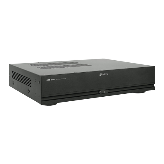
Summary of Contents for Niles MRC-6430
- Page 1 Multi Room Controller I N S T A l l A T I o N G u I d e MRC– English...
-
Page 2: Table Of Contents
CONGRATULATIONS! Thank you for trusting Niles to be the foundation of your home audio entertainment experience. The MRC-6430 has been designed to provide years of enjoyment and trouble free use. To protect your equipment from power surges and momentary power interruptions we strongly suggest you utilize a battery-backup power supply (UPS) with this equipment. - Page 3 “Mains Plug”) is used as the disconnect device and shall remain accessible and operable at all times. 18. Do not expose batteries to excessive heat such as sunshine, fire or the like. NILES AUDIO – 1-800-BUY-HIFI – 1-707-778-5733...
-
Page 4: Overview Mrc-6430
OVERVIEw mRC–6430 CHASSIS CONNECTIONS SOURCE 1-6 SERVICE ETHERNET PORT Analog source inputs Connect 10/100 with loop outputs For factory only Niles service only approved connection devices IR OUT 1-6 Page Assignable IR outputs Door bell or page input with loop output... - Page 5 AMPLIFIED OUTPUT ZONES 1- 4 Quick connect / disconnect speaker terminal for zones 1-4 AC Power Connection MAC ID PREAMP OUTPUT ZONE 1- 6 for chassis Analog stereo Preamp level programming Main Power outputs for each zone NILES AUDIO – 1-800-BUY-HIFI – 1-707-778-5733...
-
Page 6: What's Included - How To Begin
INCLUdEd: MRC-6430 1ea US Power Cord 1ea EU Power Cord 4ea Removable Speaker Connectors Quick Install Guide (this document) 2ea Rack Mount Ears 6430 WWW.NILESAUDIO.COM... -
Page 7: Mount In Cabinet Or Rack
Turn off the Main Power switch to the MRC-6430 before making connections. 1. mOUNT IN CABINET OR RACk Mount the MRC-6430 in a cabinet by setting it on a sturdy shelf. As with any electronic device the MRC-6430 generates heat at all times, but considerably more when all zones are playing. -
Page 8: Connect To Network
2. CONNECT TO NETwORk With a category 5 (or higher) cable make a connection between the Ethernet port on the MRC-6430 and an open Ethernet port on the local area network. The MRC-6430 is defaulted for DHCP addressing. Static addressing is required... -
Page 9: Connect Audio Sources
3. CONNECT AUdIO SOURCES B – LOOp OUTpUTS 1 THRU 6 CONNECTION Two MRC-6430’s may be used in a single system. This allows for 6 sources and up to 12 zones. The sources from chassis one are shared with chassis two by connecting the LOOP OUT from chassis one to the matching source AUDIO INPUT on chassis two. -
Page 10: Connect And Mount Ir Emitters
Make sure to use the included System Worksheet to note which IR port is being used for each device. When using an additional MRC-6430 chassis to add zones 7 thru 12, the six IR outputs on the 2nd chassis are available as additional unique IR outputs. -
Page 11: Connect Speakers
7. ZONE pRE-Amp OUTpUTS A – CONNECTING ZONE pRE-Amp OUTpUTS 1 THRU 6 Each zone of the MRC-6430 has a corresponding Zone Preamp Output to send signals to auxiliary amplifiers for powering more than 1 pair of speakers in a zone, powering speakers in zones 5 and 6, or adding additional power to a pair of speakers in a given zone. -
Page 12: Zone Pre-Amp Outputs
7. ZONE pRE-Amp OUTpUTS pRE-AmpS OUTpUTS 5 – 6 CONNECTION (optional use) The pre-amp zone outputs on the MRC-6430 may be used to connect to an audio/video receiver for sharing the whole-house audio system’s sources with a media room or home theater. -
Page 13: Power Up The Mrc-6430
Engage the Main Power switch on the rear and press the Standby Power Button on the front to turn the unit on. When the MRC-6430 is in Standby mode, the button dims and the internal amplification and controller are shut down. -
Page 14: Specifications
11. SpECIFICATIONS Dimensions 17 1/4”W x 4 15/16”H x 12 7/8”D with feet (437 x 100 x 328 mm) Rackmount dimensions: 17 1/4”W x 3 1/2”H (2U) x 12 7/8”D without feet (437 x 88 x 328 mm) Weight 18 lbs. (8,6 kg) Power Supply 100-120 / 220-240 V~, 50 / 60 Hz Fuse Rating... - Page 15 This warranty is not transferable to subsequent purchasers of the product. To obtain warranty service, contact the authorized dealer where you purchased your product or take the unit to the nearest authorized Niles dealer (with proof of purchase – claims made without proof of purchase will be denied) who will test the product and if necessary, forward it to Core Brands for service.
- Page 16 1 - 8 0 0 - B U Y - H I F I – w w w . n i l e s a u d i o . c o m ©2014 Core Brands, LLC. All rights reserved. Niles...
- Page 17 12. pROjECT dOCUmENTATION wORkSHEET Network DHCP-Range Unit 1 IP Address Unit 1 MAC Address Sub-Net Mask NOTES Gateway Wireless SSID Passkey Sources Name WWW.NILESAUDIO.COM...
- Page 18 Misc Network Device IP Address Misc Network Device IP Address Misc Network Device IP Address Misc Network Device IP Address PRIMARY CHASIS SECONDARY CHASIS (for expansion) IR Outputs Unit 1 Name IR Outputs Unit 2 Name NILES AUDIO – 1-800-BUY-HIFI – 1-707-778-5733...
- Page 19 12. pROjECT dOCUmENTATION wORkSHEET Zones Name Amplifier Channels WWW.NILESAUDIO.COM...
- Page 20 MAC Address IP Address MAC Address IP Address MAC Address IP Address MAC Address IP Address MAC Address IP Address MAC Address IP Address MAC Address IP Address MAC Address IP Address MAC Address NILES AUDIO – 1-800-BUY-HIFI – 1-707-778-5733...


Need help?
Do you have a question about the MRC-6430 and is the answer not in the manual?
Questions and answers