Table of Contents
Advertisement
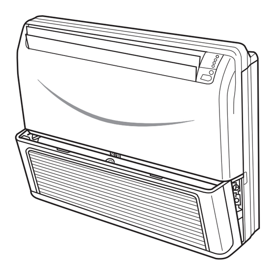
Convertible Type Low Ambient Cooling Series
HCFU-14CL03/R1
HCFU-18CL03/R1
HCFU-24CL03/R1
HCFU-28CM03/R1
HCFU-36CM03/R1
HCFU-42CM03/R1
Features
Super low outdoor ambient cooling at -15
Auto-restart function
Group control(with a group controller)
Auto-changeover
Compact design of indoor unit
Weekly timing(with a weekly timer)
With new environment friendly refrigerant R407C
MANUAL CODE: SYJS-006
Service Manual
Commercial Air Conditioning
(AC142ACNAC+AU142ABNAC)
(AC182ACNAC+AU182ABNAC)
(AC242ACNAC+AU242ABNAC)
(AC28NACNAC+AU28NABNAC)
(AC36NACNAC+AU36NABNAC)
(AC42NACNAC+AU42NABNAC)
Haier Group
EDITION:2002.12.31.
Advertisement
Table of Contents

Related Manuals for Haier AC142ACNAC


Summary of Contents for Haier AC142ACNAC
-
Page 1: Service Manual
Service Manual Commercial Air Conditioning Convertible Type Low Ambient Cooling Series HCFU-14CL03/R1 (AC142ACNAC+AU142ABNAC) HCFU-18CL03/R1 (AC182ACNAC+AU182ABNAC) HCFU-24CL03/R1 (AC242ACNAC+AU242ABNAC) HCFU-28CM03/R1 (AC28NACNAC+AU28NABNAC) HCFU-36CM03/R1 (AC36NACNAC+AU36NABNAC) HCFU-42CM03/R1 (AC42NACNAC+AU42NABNAC) Features Super low outdoor ambient cooling at -15 Auto-restart function Group control(with a group controller) Auto-changeover Compact design of indoor unit... -
Page 2: Table Of Contents
CONTENTS CONTENTS Contents……..........…...………...…….1 1. Description of Products & Features…………………...…….1 2. Specifications…………………………. ………………...……3 3. Safety precaution…………………………..………………….9 4. Net dimensions of indoor and outdoor unit………………...11 5. Installation instructions ……………………. ………………..17 6. Parts and functions …………………………..…… ..……….28 7. Remote controller functions………………………….………31 8. Refrigerant diagram…………………………..……………..43 9. -
Page 3: Description Of Products & Features
“H” refer to cooling and heating, ”C” refer to cooling only Nominal cooling capacity (BTU/h), 42=42000BTU/h Indoor and outdoor unit code: "CF" Convertible type; "U" Outdoor unit “H” means “Haier” New code A C 42 N A C N A C... - Page 4 DESCRIPTION OF PRODUCTS & FEATURES 1.4 Products characteristic (1).Low ambient temperature cooling technology The system can run the cooling operation at the low ambient temperature -15 (2).HFC refrigerant technology To protect the environment, we have adopted the HFC refrigerant. The HFC R407C is of zero ODP for the purpose of environmental protection.
-
Page 5: Specifications
EER or COP BTU/W Dehumidifying capacity 10‐³×m³/h 1PH, 220V-230V, 50HZ Power source PH-V-Hz Running current/Starting current 9.4/40.7 Power cable AC142ACNAC / WHITE Unit model (color) CENTRIFUGAL×2 Type × Number 1070/1000/940 Speed r/min Air-flow(H-M-L) m³/h TP2M/9.52 Heat exchanger Type / Diameter Flow 0.199... - Page 6 SPECIFICATIONS Item Model HCFU-18CL03/R1 Function Cooling Heating 18000 Capacity BTU/h Total power input 2000 9.00 EER or COP BTU/W Dehumidifying capacity 10‐³×m³/h 1PH, 220V-230V, 50HZ Power source PH-V-Hz 9.3/46.0 Running current/Starting current Power cable AC182ABNAC / WHITE Unit model (color) CENTRIFUGAL×2 Type ×...
- Page 7 SPECIFICATIONS Item Model HCFU-24CL03/R1 Function Cooling Heating 24000 Capacity BTU/h Total power input 2800 8.57 EER or COP BTU/W Dehumidifying capacity 10‐³×m³/h 1PH,220V~230V,50Hz Power source PH-V-Hz Running current/Starting current 12.5/60.1 Power cable AC242ACNAC / WHITE Unit model (color) CENTRIFUGAL×2 Type × Number 1300/1200/1000 Speed r/min...
- Page 8 SPECIFICATIONS Item Model HCFU-28CM03/R1 Function Cooling Heating 28000 Capacity BTU/h Total power input 2800 10.0 EER or COP BTU/W Dehumidifying capacity 10‐³×m³/h 3N,380V~400V,50Hz Power source PH-V-Hz Running current/Starting current 12.5/60.1 Power cable AC28NACNAC / WHITE Unit model (color) CENTRIFUGAL×2 Type × Number 1300/1200/1000 Speed r/min...
- Page 9 SPECIFICATIONS Item Model HCFU-36CM03/R1 Function Cooling Heating 36000 Capacity BTU/h Total power input 3600 10.0 EER or COP BTU/W Dehumidifying capacity 10‐³×m³/h 3N, 380V-400V, 50HZ Power source PH-V-Hz Running current/Starting current 6.4/32 Power cable AC36NACNAC / WHITE Unit model (color) CENTRIFUGAL×3 Type ×...
- Page 10 SPECIFICATIONS Item Model HCFU-42CM03/R1 Function Cooling Heating 42000 Capacity BTU/h Total power input 4600 EER or COP BTU/W Dehumidifying capacity 10‐³×m³/h 3N, 380V-400V, 50HZ Power source PH-V-Hz Running current/Starting current 9.3/32 Power cable AB42NACNAC / WHITE Unit model (color) CENTRIFUGAL×3 Type ×...
-
Page 11: Safety Precaution
SAFETY PRECAUTIONS 3 SAFETY PRECAUTIONS Please read these "Safety Precautions" first then accurately execute the installation work. Though the precautionary points indicated herein are divided under two headings, WARNING those points which are related to the strong possibility of an installation done in error CAUTION WARNING resulting in death or serious injury are listed in the... -
Page 12: Safety Precautions
SAFETY PRECAUTIONS WARNING When setting up or moving the location of the air conditioner, do not mix air etc. or anything other than the designated refrigerant (please see nameplate) within the refrigeration cycle. Rupture and injury caused by abnormal high pressure can result from such mixing. Always use accessory parts and authorized parts for installation construction. -
Page 13: Net Dimensions Of Indoor And Outdoor Unit
NET DIMENSIONS OF INDOOR AND OUTDOOR UNIT 4 NET DIMENSIONS OF INDOOR AND OUTDOOR UNIT Model: HCFU-14CL03/R1 HCFU-18CL03/R1 Indoor unit Model: HCFU-14CL03/R1 HCFU-18CL03/R1 Outdoor unit 100 100... - Page 14 NET DIMENSIONS OF INDOOR AND OUTDOOR UNIT Model: HCFU-24CL03/R1 HCFU-28CM03/R1 Indoor unit...
- Page 15 NET DIMENSIONS OF INDOOR AND OUTDOOR UNIT Model: HCFU-24CL03/R1 HCFU-28CM03/R1 Outdoor unit Screw Hole (M10) 1024 Power Wiring Terminal Power Wiring Distribution Hole Back Air-flow Hole Installation Servicing Space(at Least) Unit:mm Back Air- flow Hole Installation Outlet Air-flow Hole Repairing Space Dimension Leave space Leave space Note (1) Fix the parts with screws...
- Page 16 NET DIMENSIONS OF INDOOR AND OUTDOOR UNIT Model: HCFU-36CM03/R1 HCFU-42CM03/R1 Indoor unit drainage pipe 1920 1800...
- Page 17 NET DIMENSIONS OF INDOOR AND OUTDOOR UNIT Model: HCFU-36CM03/R1 HCFU-42CM03/R1 Outdoor unit Screw Hole (M10) Power wiring Terminal Back Air-flow Hole Installation Servicing Space(at Least) Unit:mm Back Air- Installation flow Hole Outlet Air-flow Hole Repairing Space Dimension Leave space Leave space Note : (1).
-
Page 18: Installation Instructions
INSTALLATION INSTRUCTIONS 5 INSTALLATION INSTRUCTIONS For authorized service personnel only WARNING (1) For the room air conditioner to operate satisfactorily, install it as outlined in this installation manual. (2) Connect the indoor unit and outdoor unit with the room air conditioner piping and cords available from our standard parts. - Page 19 INSTALLATION INSTRUCTIONS Fig. 1 Fig. 2 Floor console may be different 1.5m 30 cm or more 40 cm or more 30 cm Left or more Right 60 cm or more For series 14,18 30 cm 60 cm 30 cm 1.5m or more or more or more...
- Page 20 INSTALLATION INSTRUCTIONS STANDARD PARTS The following installation parts are furnished. Use them as required. ACCESSORIES Q'ty Application Name and shape Name and shape Q'ty Application Cover plate (left) For fixing the wall Tapping screw For series 24,28, 36,42 bracket. ( 4x20) the two cover plate are For series 24,28,36,42 not available...
-
Page 21: Connection Pipe Requirement
INSTALLATION INSTRUCTIONS CONNECTION PIPE REQUIREMENT Table 1 Wall (Fig. 6) Maximum height Diameter Maximum (between indoor Series length Liquid side Gas side and outdoor) Indoor unit outdoor unit 14,18 6.35 mm 15.88 mm 15 m For series 14,18 when installing set to wall, install the accessory wall bracket at the position shown in Fig.7, 30 m 15 m... - Page 22 INSTALLATION INSTRUCTIONS B. UNDER CEILING TYPE 3. INSTALLING BRACKETS Using the installation template, drill holes for piping and anchor bolts(for Install the brackets with nuts, washers and spring holes).(Fig.12) washers.(Fig. 17) Fig. 12 Fig. 17 900mm Drilling position for anchor bolt Installation template 200mm...
-
Page 23: Outdoor Unit Installation
INSTALLATION INSTRUCTIONS Fig. 22 5. INSTALL THE DRAIN HOSE Select whether the drain hose will be connected to the left or right Width across flats side.(Fig.5) L dimension Insert the drain hose into the drain pan, then secure the drain hose Liquid pipe with a nylon fastener.(Fig.8) 1.6 to 1.8mm(6.35mm dia) -
Page 24: Refrigerant Piping
INSTALLATION INSTRUCTIONS Fig. 25 Install the removed flare nuts (a) Concrete foundation (b) Foundation anchor to the pipes to be connected, 90 •0.5 Unit then flare the pipes. Unit Anchor bolt Concrete foundation (3) Limitations for one way piping length and vertical height difference. - Page 25 INSTALLATION INSTRUCTIONS Open the handle at low in gaugemanifold, operate Open vacuum pump. If the scale-moves of gause (low) reach vacuum condition in a moment, check 1 again. Vacuumize for over 15min. And check the level gauge which should read -0.1 MPa (-76 cm Hg) at low pressure side.
-
Page 26: How To Connect Wiring To The Terminals
INSTALLATION INSTRUCTIONS If needing to remove the refrigerant gas when installation or repair , please refer to the following procedures: 1. Cut off the power 2. (After confirming the power is cut off) pull the power cable plug terminals of the low-pressure pressure-switch out. - Page 27 INSTALLATION INSTRUCTIONS (2) Pull out the electric component box. ELECTRICAL REQUIREMENT Fig. 32 Electric wire size and fuse capacity: Table 5 Series 14,18 24,28 36,42 Connection cord Electric component box Fuse capacity(A) (3) Remove the electric component box cover. ELECTRICAL WIRING Fig.
-
Page 28: Electrical Wiring
INSTALLATION INSTRUCTIONS ELECTRICAL WIRING WARNING Cover plate (Right) Fig. 35 (1) Always use a special branch circuit and install a special receptacle to supply power to the room air conditioner. (2) Use a circuit breaker and receptacle matched to the capacity of the room air conditioner. -
Page 29: Parts And Functions
PARTS AND FUNCTIONS 6 PARTS AND FUNCTIONS 6.1 Drawings POWER OPER TIMER COMP EMER Fig.2 Fig.1 For series 14,18 Fig.3 EMER POWER OPER TIMER For series 36,42 Fig.1 Indoor Unit Fig.3 1 Operating Control Panel (Fig.2) 2 Emergency switch 3 Remote Control Signal Receiver 4 Power Indicator Lamp (Red) 5 OPERATION Indicator Lamp (Green) 6 TIMER Indicator Lamp (Yellow) -
Page 30: Remote Controller Functions
REMOTE CONTROLLER FUNCTIONS 7 REMOTE CONTROLLER FUNCTIONS INTRODUCTION TO SPARE PARTS Buttons and display of the remote controller. Power ON/OFF TEMP Used for unit start and Used to select your stop. desired temp. SWING Used to set auto fan AUTO direction. -
Page 31: Fan Speed
REMOTE CONTROLLER FUNCTIONS INTRODUCTION TO SPARE PARTS Buttons and display of the remote controller. HEAT FAN OPERATION COOL AUTO SIGNAL SENDING AUTO TEMP. SWING TEMP SWING CLOCK FAN SPEED MODE LOCK CLOCK TIMER SLEEP AUTO TIMER OFF LOCK RESET AUTO TIMER ON SLEEP Clock set... -
Page 32: Remote Controller Operation
REMOTE CONTROLLER FUNCTIONS REMOTE CONTROLLER OPERATION Remote controller's operation When in use, put the signal transmission head directly to the receiver hole on the indoor unit. The distance between the signal transmission head and the receiver hole should be within 7m without any obstacle as well. - Page 33 REMOTE CONTROLLER FUNCTIONS GUIDE TO OPERATION FAN operation (1) Unit start Press ON/OFF button, unit starts. Previous operation status appears on display. (Not Timer setting) Power indicator on indoor unit lights up. (2) Select operation mode Press MODE button. For each press, operation mode changes as follows: AUTO COOL HEAT...
-
Page 34: Guide To Operation
REMOTE CONTROLLER FUNCTIONS GUIDE TO OPERATION AUTO run, COOL,HEAT and DRY operation Use COOL in summer. Recommendations Use HEAT in winter. Use DRY in spring,autumn and in damp climate. (1) Unit start Press ON/OFF button, unit starts. Previous operation status appears on display.(Not Timer setting) Power indicator on indoor unit lights up. -
Page 35: Fan Speed Selection
REMOTE CONTROLLER FUNCTIONS GUIDE TO OPERATION (4) Fan speed selection Press FAN button. For each press, fan speed changes as follows: AUTO AUTO COOL operation starts when room Unit runs at the speed displayed on LCD. temp. is higher than temp. setting. Ultra-low air flow In HEAT mode, warm air will blow out after a short period Temp. -
Page 36: Timer Operation
REMOTE CONTROLLER FUNCTIONS GUIDE TO OPERATION TIMER operation Set Clock correctly before starting Timer operation(refer to page 6) You can let unit start or stop automatically at following times: Before you wake up in the morning, or get back from outside or after you fall asleep at night. TIMER ON/OFF (1)After unit start, select your desired operation mode. - Page 37 REMOTE CONTROLLER FUNCTIONS GUIDE TO OPERATION TIMER ON-OFF (1)After unit start, select your desired operation mode Operation mode will be displayed on LCD. Power indicator on indoor unit lights up. (2)Press TIMER button to change TIMER mode Every time the button is pressed, display changes as follows: blank TIMER ON TIMER OFF...
-
Page 38: Air Flow Direction Adjustment Procedure
REMOTE CONTROLLER FUNCTIONS AIR FLOW DIRECTION ADJUSTMENT PROCEDURE Adjusting up/down air flow direction Up/down direction can be adjusted by using the SWING button on the remote c ontroller. Each time pressing this button, the mode changes in the following sequence. No indication SWING (louver stopped) - Page 39 REMOTE CONTROLLER FUNCTIONS Comfortable Sleep At night, before going to bed you can press down the SLEEP button on the controller and the air-conditioner will run by the comfortable sleeping mode to make you sleep more comfortable. Press SLEEP button once to make the air conditioner have the previous-set sleep time (first power-on is "1h"), the sleep symbol will appear.
- Page 40 REMOTE CONTROLLER FUNCTIONS Remote Control: There is a telecommunication interface for remote control on the control panel of the indoor unit. After the peripheral equipment have been installed in accordance with the instruction manual of the selected remote control detector, the air conditioner will be computerized and controlled from a far-away place.
-
Page 41: Refrigerant Diagram
REMOTE CONTROLLER FUNCTIONS & REFRIGERANT DIAGRAM 7.2 Dimensions of the controller REMOTE CONTROL UINT MODEL YR-D23 1.DO NOT MIX OLD WITH NEW BATTE RIES AND DO NOT USE BATTERIES OF DIFFERENT TYPES TOGETHER 2.INSERT CORRECTLY 2 TWO R-03 BATTERIES IN THE POLARITY TEMP 3.PLEASE REMOVE THE BATTERIES... -
Page 42: Electrical Control Functions
ELECTRICAL CONTROL FUNCTIONS 9 ELECTRICAL CONTROL FUNCTIONS 9.1 Control Features The brief introduction includes those for each item of various types of air conditioners and The brief introduction includes those for each item of various types of air conditioners and their electric control functions. - Page 43 ELECTRICAL CONTROL FUNCTIONS (2) Auto Selection of Wind Speed In the following, Tr means room temperature while Ts means setting temperature. a. During cooling program conversion of wind speed from the low to high won’t work until the present speed has continued for 3 minutes while conversion from the high to low needs no time delay.
- Page 44 ELECTRICAL CONTROL FUNCTIONS blowing fan runs at setting wind speed. This working area is defined as area A. (2) Ts Tr Ts + 2 , the compressor and outdoor blowing fan run for 10 minutes then pause for 6 minutes, while indoor blowing fan runs at low wind speed. This working area is defined as area B.
- Page 45 ELECTRICAL CONTROL FUNCTIONS setting wind speed. (6) Afterheat blowing during heating program During heating program, the compressor will stop running (except overheat protection or frost removal) while the indoor blowing fan will firstly run for 50 seconds at low speed then stop.
-
Page 46: Electrical Control Functions
(12) Monitoring of remote network Through preset interface, the air conditioner is connected to remote control detector (made by Haier) with 2-core cables for wire communication, to execute instructions sent from computer or centralized controller via remote control detector and meanwhile send present running status and trouble information of the machine to remote control detector. - Page 47 ELECTRICAL CONTROL FUNCTIONS 9.2 Introduction to the fan speed controller 210V The low ambient temperature cooling system realizes starting normally at the temperature -15 by the method of: The sensor collects the coil temperature to change the voltage of the outdoor fan motor, thus to change the fan speed. As a result, the system pressure is restricted.
- Page 48 ELECTRICAL CONTROL FUNCTIONS 9.3 Defrost operation flow chart Come to defrost Compressor Open outdoor fun Compressor Condition off or 55s? E-Heat off for 30s? compress Return Operation indoor fun motor Return 4-way value Turn off compressor Return outdoor fun compressor Compressor ON ? Turn off for...
-
Page 49: Diagnostic Information(Trouble Shooting)
DIAGNOSTIC INFORMATION (TROUBLE SHOOTING) 10 DIAGNOSTIC INFORMATION (TROUBLE SHOOTING) 10.1 Fault codes Flash time of compressor Code Trouble contents (new) running indicate lamp drainage system trouble indoor temperature sensor broken indoor coil temperature sensor broken outdoor temperature sensor broken outdoor coil temperature sensor broken over current protect limit pressure protect three phase protect... - Page 50 DIAGNOSTIC INFORMATION (TROUBLE SHOOTING) 10.2 Trouble shooting - Detailed for engineer...
- Page 51 DIAGNOSTIC INFORMATION (TROUBLE SHOOTING)
- Page 52 DIAGNOSTIC INFORMATION (TROUBLE SHOOTING)
- Page 53 DIAGNOSTIC INFORMATION (TROUBLE SHOOTING)
-
Page 54: Electrical Data
ELECTRICAL DATA 11 ELECTRICAL DATA 11.1 Wiring Diagram HCFU-14CL03/R1 HCFU-18CL03/R1... - Page 55 ELECTRICAL DATA HCFU-24CL03/R1 INDOOR WIRING DIAGRAM SIGNAL RECEIVER PIPING BOARD TEMP. SENSOR AMBIENT TEMP. SENSOR LOUVER MOTOR INDOOR PCB FAN MOTOR REMOTE CONTROL DETECTOR 3.15A/250V FUSE CAPACITOR TRANSFORMER R: RED NOTE: B: BLACK W: WHITE THE PART IN THE DASHED FRAME IS TO OUTDOOR UNIT Y/G: YELLOW/GREEN OPTIONAL ELEMENT...
- Page 56 ELECTRICAL DATA HCFU-28CM03/R1 INDOOR WIRING DIAGRAM SIGNAL RECEIVER PIPING BOARD TEMP. SENSOR AMBIENT TEMP. SENSOR LOUVER MOTOR INDOOR PCB FAN MOTOR REMOTE CONTROL DETECTOR 3.15A/250V FUSE CAPACITOR TRANSFORMER R: RED NOTE: B: BLACK W: WHITE THE PART IN THE DASHED FRAME IS TO OUTDOOR UNIT Y/G: YELLOW/GREEN OPTIONAL ELEMENT...
- Page 57 ELECTRICAL DATA HCFU-36CM03/R1 HCFU-42CM03/R1 INDOOR WIRING DIAGRAM SIGNAL RECEIVER PIPING BOARD TEMP. SENSOR AMBIENT TEMP. SENSOR LOUVER MOTOR INDOOR PCB FAN MOTOR REMOTE CONTROL DETECTOR 3.15A/250V FUSE CAPACITOR FAN MOTOR CAPACITOR TRANSFORMER R: RED NOTE: B: BLACK THE PART IN THE DASHED FRAME IS W: WHITE TO OUTDOOR UNIT Y/G: YELLOW/GREEN...
- Page 58 ELECTRICAL DATA 11.2 Circuit Diagram 11.2.1 Indoor unit HCFU-14CL03/R1...
- Page 59 ELECTRICAL DATA HCFU-18CL03/R1 CN13 LM358 LM358 Y.S.J CN12 9014 9014 2803 0.01UF/275 W.F.J 5.6K H.X.F 9014 TEST RESET XOUT VREF TMP87C846 101K PUMP CN11 4148 EX TH H IGH PIN . COOLING 331K COOLING ONLY HEATING 600D 4.7UF/50V NO AUTO AUTO RESTART RESTART...
- Page 60 ELECTRICAL DATA HCFU-24CL03/R1 HCFU-28CM03/R1 HCFU-36CM03/R1 HCFU-42CM03/R1 R24 33K 10K/0.5W TM P87PH4 6N EEPROM 93C46 10K/0.5W 4007 TLP371 4007 2.2K 5.6K 5.6K 5.6K TLP521 2803 9014 PUMP CN12 TEST PUMP RESET 5.6K XOUT VREF 9014 9014 0.01UF/275 CN11 Pin. high low CHECK cooling cooling...
-
Page 61: Outdoor Unit
ELECTRICAL DATA 11.2.2 Outdoor unit T600D 4.7UF/50V ULN2003A TMP87P808N 8MHz RESET TEST 2PIN HEAT COOL 2PIN TEST VAREF TLP371 2.2K 5.6K EX HT 5.1K 10UF/16V 10K/0.5W 4007 TLP521-1 5.1K 10K/0.5W 10UF/16V TM TH Pin. high low 62K/1W*3 2 speed single speed 4148 standard 200K... - Page 62 ELECTRICAL DATA 11.3 Thermostat chart (Sensor resistance-temperature graph) Model: HCFU-14CL03/R1 HCFU-18CL03/R1 HCFU-24CL03/R1 HCFU-28CM03/R1 HCFU-36CM03/R1 HCFU-42CM03/R1 Ambient temperature sensor Coil temperature sensor Indoor Ambient temperature sensor Coil temperature sensor Fan speed controller sensor Outdoor...
- Page 63 ELECTRICAL DATA...
- Page 64 ELECTRICAL DATA...
- Page 65 ELECTRICAL DATA...
- Page 66 EXPLODED VIEWS & PARTS LISTS 12 EXPLODED VIEWS & PART LISTS 12.1 Model HCFU-14CL03/R1 HCFU-18CL03/R1 indoor unit...
-
Page 67: Exploded Views And Parts Lists
EXPLODED VIEWS & PARTS LISTS HCFU-14CL03/R1 HCFU-18CL03/R1 Part list of indoor unit Name of part specialized number QTY. Remark air filter 001A2400087 inlet grill assy 001A0100330 fixing plate 001A1301398 strengthen tendon 001A1301395 pinch plate 001A1301399 wiring assembly 001A4400509 Fan motor capacitor 2uf 001A3600009B transformer 001A3800141... - Page 68 EXPLODED VIEWS & PARTS LISTS Model HCFU-14CL03/R1 HCFU-18CL03/R1 outdoor unit...
- Page 69 EXPLODED VIEWS & PARTS LISTS HCFU-14CL03/R1 HCFU-18CL03/R1 Part list of outdoor unit Name of parts Part specialized code QTY. Remark Front guard assy. 001A0100122 Front panel 001A1101038 Axial fan 001A2331024 Fan mortor 001A3000026 Motor mounting plate 001A1301133 Condenser assy. 001A0400130 Slide plate(left) 001A0100356 handle...
- Page 70 EXPLODED VIEWS & PARTS LISTS 12.2 Model HCFU-24CL03/R1 HCFU-28CM03/R1 indoor unit...
- Page 71 EXPLODED VIEWS & PARTS LISTS Name of parts Part specialized code QTY. Remark inlet grill assy 001A1231278 air filter 001A2400108 front panel assy 001A1101174 001A17341062 Pipe temperature sensor 001A3900006 drain pan assy 001A1200185 mounting plate 001A1101179 left scroll case 001A1301574 motor holder 001A1301581 centrifugal fan...
- Page 72 EXPLODED VIEWS & PARTS LISTS Model HCFU-24CL03/R1 HCFU-28CM03/R1 outdoor unit...
- Page 73 EXPLODED VIEWS & PARTS LISTS HCFU-24CL03/R1 HCFU-28CM03/R1 Part list of outdoor unit Name of parts Part specialized code QTY. Remark Front grille 001A1236028 handle 001A1436160 Front panel 001A1101078 service panel assy 001A0100524 Axial fan 001A5402022 Fan motor 001A3000082 Bracket for fan motor 001A0100266 Condenser assy.
- Page 74 EXPLODED VIEWS & PARTS LISTS 12.3 Model HCFU-36CM03/R1 HCFU-42CM03/R1 indoor unit...
- Page 75 EXPLODED VIEWS & PARTS LISTS Part list of indoor unit HCFU-36CM03/R1 HCFU-42CM03/R1 Name of parts Part specialized code QTY. Remark inlet grill assy 001A1231278 air filter 001A2400108 front panel assy 001A1101167 001A17341009 Eletrical box 001A13011280 Eletrical box cover 001A1301379 0010400407 transformer 001A3800066 capacitor...
- Page 76 EXPLODED VIEWS & PARTS LISTS HBU-36CM03/R1 HBU-42CM03/R1 Outdoor Units...
- Page 77 EXPLODED VIEWS & PARTS LISTS HCFU-36CM03/R1 HCFU-42CM03/R1 Part list of indoor unit Name of parts Part specialized code QTY. Remark Front grille 001A1236028 Front panel 001A0100492 Axial fan 001A5402022 Fan motor 001A3000244 Bracket for fan motor 001A0100740 AC contactor 001A3900161 Capacitor for fan motor 001A3600018 Condenser assy.
- Page 78 PERFORMANCE CURVES 13 PERFORMANCE CURVES HCFU-14CL03/R1 Cooling capacity graph 6.50 6.00 5.50 5.00 4.50 4.00 3.50 3.00 2.50 Indoor 2.00 DB( ) 1.50 1.00 Outdoor temperatur( ) EER graph 5.00 4.50 4.00 3.50 3.00 2.50 2.00 1.50 Indoor 1.00 DB( ) 0.50 0.00 Outdoor temperature( )
- Page 79 PERFORMANCE CURVES HCFU-18CL03/R1 Cooling capacity graph 7.50 7.00 6.50 6.00 5.50 5.00 4.50 4.00 3.50 3.00 Indoor DB( ) 2.50 2.00 Outdoor temperature( ) EER graph 5.00 4.50 4.00 3.50 3.00 2.50 Indoor 2.00 DB( ) 1.50 1.00 Outdoor temperature( )
- Page 80 PERFORMANCE CURVES HCFU-24CL03/R1 Cooling capacity graph 10.00 9.00 8.00 7.00 6.00 5.00 4.00 3.00 2.00 Indoor 1.00 DB( ) 0.00 Outdoor temperature( ) EER graph 4.50 4.00 3.50 3.00 2.50 2.00 1.50 1.00 Indoor 0.50 DB( ) 0.00 Outdoor temperature( )
- Page 81 PERFORMANCE CURVES HCFU-28CM03/R1 Cooling capacity graph 12.00 11.00 10.00 9.00 8.00 7.00 6.00 5.00 4.00 3.00 2.00 Indoor 1.00 DB( ) 0.00 Outdoor temperature( ) EER graph 5.00 4.50 4.00 3.50 3.00 2.50 2.00 1.50 1.00 Indoor 0.50 DB( ) 0.00 Outdoor temperature( )
- Page 82 PERFORMANCE CURVES HCFU-36CM03/R1 Cooling capacity graph 18.00 16.50 15.00 13.50 12.00 10.50 9.00 7.50 6.00 4.50 3.00 Indoor 1.50 DB( ) 0.00 Outdoor temperature( ) EER graph 4.50 4.00 3.50 3.00 2.50 2.00 1.50 1.00 Indoor 0.50 DB( ) 0.00 Outdoor temperature( )
- Page 83 PERFORMANCE CURVES HCFU-42CM03/R1 Cooling capacity graph 20.0 17.5 15.0 12.5 10.0 Indoor DB( ) Outdoor DB( EER graph Indoor DB( ) Outdoor DB(...
- Page 84 NOISE LEVEL TEST CHART 14 NOISE LEVEL TEST CHART...
-
Page 85: Air Velocity Distribution
AIR VELOCITY DISTRIBUTION 15 AIR VELOCITY DISTRIBUTION 15.1 Floor type Model: HCFU-14CL03/R1 HCFU-18CL03/R1 a. Cooling / Air Velocity Distribution Cooling Blowy angle: 25 Air Velocity Distribution 0.5m/s 1.0m/s 1.5m/s b. Cooling / Temperature Distribution Cooling Blowy angle:25 Temperature Distribution... - Page 86 AIR VELOCITY DISTRIBUTION Model: HCFU-24CL03/R1 HCFU-28CM03/R1 a. Cooling / Air Velocity Distribution Cooling Blowy angle:25 Air Velocity Distribution 0.5m/s 1.0m/s 1.5m/s b. Cooling / Temperature Distribution Cooling Blowy angle:25 Temperature Distribution...
- Page 87 AIR VELOCITY DISTRIBUTION Model: HCFU-36CM03/R1 HCFU-42CM03/R1 a. Cooling / Air Velocity Distribution Cooling Blowy angle:25 Air Velocity Distribution 0.5m/s 1.0m/s 1.5m/s b. Cooling / Temperature Distribution Cooling Blowy angle:25 Temperature Distribution...
- Page 88 AIR VELOCITY DISTRIBUTION 15.2 Ceiling type Model: HCFU-14CL03/R1 HCFU-18CL03/R1 a. Cooling / Air Velocity Distribution Cooling Blowy angle: 25 Air Velocity Distribution 1.0m/s 0.5m/s b. Cooling / Temperature Distribution Cooling Blowy angle:25 Temperature Distribution...
- Page 89 AIR VELOCITY DISTRIBUTION Model: HCFU-24CL03/R1 HCFU-28CM03/R1 a. Cooling / Air Velocity Distribution Cooling Blowy angle:25 Air Velocity Distribution 1.0m/s 0.5m/s b. Cooling / Temperature Distribution Cooling Blowy angle:25 Temperature Distribution...
- Page 90 AIR VELOCITY DISTRIBUTION Model: HCFU-36CM03/R1 HCFU-42CM03/R1 a. Cooling / Air Velocity Distribution Cooling Blowy angle:25 Air Velocity Distribution 1.0m/s 0.5m/s b. Cooling / Temperature Distribution Cooling Blowy angle:25 Temperature Distribution...
- Page 91 Sincere Forever Tel: 86-532-8938356 Web site: http: //www.haier.com...
Need help?
Do you have a question about the AC142ACNAC and is the answer not in the manual?
Questions and answers