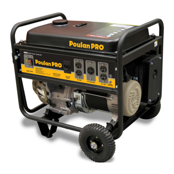
Poulan Pro PPG6000 Service Manual
Portable electric generator
Hide thumbs
Also See for PPG6000:
- Owner's manual (32 pages) ,
- Owner's manual (32 pages) ,
- Service manual (43 pages)
Table of Contents
Advertisement
Advertisement
Table of Contents
Troubleshooting

Related Manuals for Poulan Pro PPG6000


Summary of Contents for Poulan Pro PPG6000
- Page 1 Portable Electric Generator Service Manual Model: PPG6000...
-
Page 2: Table Of Contents
Contents Chapter 1 General Information…………………………………………….. 3-7 General Description of Generator…………………………………. 3 Safety Information…………………………………………………… 4 Model Parameters…………………………...………………………. 5 Maintenance and Adjusting Data……………..……………………. 5-7 Chapter 2 Maintenance of the Generator Set………………………………8 2.1 Maintenance of Starting System……………………………….. 8-10 2.2 Maintenance of Lubrication System…………………………… 10-11 2.3 Maintenance of Inlet System……………………………………... -
Page 3: Chapter 1 General Information
Chapter 1 General Information PPG6000 Generator is equipped with a single cylinder, 4 stroke, forced air-cooled, OHV 25° slant, internal combustion engine. It is equipped with an electronic ignition system and is tuned to meet all EPA and California Emissions Requirements. -
Page 4: Safety Information
Safety Information: This symbol is known as the safety alert symbol and points out safety instructions that can lead to injury or death. Attention: Please read and understand this manual and the safety information prior to starting the Generator. Danger: Indicates an imminently hazardous situation which, if not avoided, will result in death or serious injury. -
Page 5: Specifications
Specifications PPG6000 Dimension/Weight Engine Model PPG6000 26.8x20x21.3 LxHxW - Inches 185lb Net Weight, Box Incl. Gross Weight, Full of 220lb Fuel Model OHV13H Engine Type 4-stroke, overhead valve, cylinder tilt 25° Cylinder discharge 389 cc capacity Bore x Stroke 88x64 mm... -
Page 6: Maintenance And Adjusting Data
Generator Maintenance and Adjusting Data Tolerance Parameters Parts Item Standard Extreme Max/Min 3750+ 150, No Load Max Speed 588- 834KPa@600RPM Cylinder Pressure 85-120PSI@600PSI 88.00mm, 3.465" 88.17mm, 3.471" Cylinder Cylinder bore diameter .10mm, .004" Warpage 6.60mm, .260" 6.75mm, .2657" Valve bushing 87.985mm, 3.464"... - Page 7 Torque Values Torque Torque in*lbf *except where note Connecting rod bolt M8X1.25(special bolt) Cylinder head bolt M10X1.25 *83 ft*lbf Flywheel nut M16X1.5(special nut) Rocker shaft nut M6X.5 Rocker shaft bolt M8X1.25(special bolt) Fuel switch connecting nut M10X1.25 Exhaust pipe connecting M8X1.25 nut/bolt Air filter bolts...
- Page 8 Generator Information Area Item Standard Service Limit Main Winding Resistance .2 ohms Field Winding Resistance 52-62 ohms Exciter Winding Resistance 1.2 ohms Main Winding Resistance .4 ohms Carbon Brush length Length .9mm, .354" 5mm, .197" EPA and Engine Serial Number are located on the panel side of the generator in the location shown.
-
Page 9: Chapter 2 Maintenance Of The Generator Set
Chapter 2 Maintenance of the Generator Set 2.1 Maintenance of the Manual Starting System The integral configuration of the starting device is shown below. Check the condition of the starter. Replace if damaged. There is a spring inside the starter device that is under stress. Wear safety goggles and watch for flying debris when it is removed. - Page 10 1. Inspect the rope for abrasions. Replace as necessary. 2. Dismantle the starter pawl guide bolt with a socket. 3. Remove the pawls and pawl spring. 4. Visually inspect all parts. 5. Inspect the flute of the starting draw wheel. 6.
-
Page 11: Maintenance Of Lubrication System
2.2 Maintenance of the Lubrication System Chose the oil type according to the local temperature of operation. Use Four-stroke engine oil. SE, SF or equivalent to SG grade oil (SAE-30). When temp is below 50°F SAE 10W30 is recommended. SAE 5W-30 is recommended when temp is below 5°F. 1. - Page 12 Cleaning the element (foam pad) Dip the element in the detergent and wring it out. Apply motor oil and wring out excess oil. Install element. 3. Remove the plastic inner housing by removing the six nuts around the perimeter. 4. Remove the enclosure by removing the two nuts inside the enclosure and one on the backside.
-
Page 13: Maintenance Of Fuel System
2.4 Maintenance of Fuel System 1. Remove the bowl of the fuel cock. 2. Remove the screen inside the fuel cock. 3. Remove the fuel cock. 4. Pull out the screen inside the tank. 5. Clean or replace both screens and reassemble. -
Page 14: Maintenance Of Exhaust System
2.5 Maintenance of the Exhaust System 1. Remove the outer heat shield from the muffler. 2. Bend the anti-rotation tabs back around the engine exhaust bolts. 3. Remove the bolts from the engine side of the exhaust pipe. 4. Remove the two bolts from the muffler to the generator head to separate the muffler from the generator. -
Page 15: Maintenance Of Ignition System
2.6 Maintenance of the Ignition System 1. Check the gap between the ignition coil and the flywheel. The gap should be 0.4mm + 0.2mm, .016” + .007”. 2. Check the status of the spark from the ignition coil. It should be a blue spark and must be above 10,000 Volts. -
Page 16: Maintenance Of Generator
8. Remove the spark plug. Check the cylinder pressure. Is should fall in the values noted in section 1.1 of this manual. If the plug is brown in color the engine is working normally. 9. Check for carbon build up on the spark plug. Check the gap of the spark plug. The values for the gap are found in section 1.1 of this manual. - Page 17 3. Remove the screws on the outside of the generator head housing. 4. Remove the AVR (large plastic part with wires coming out) Automatic Voltage Regulator. 5. Remove the bolts in the brushes, and remove the brushes. 6. Remove the mounting nuts from the rubber engine and generator head mounts. There are four total, two under the engine and two under the generator head.
- Page 18 9. Remove the generator stator. 10. Check the stator and rotor for damage or burnt wires. If there are any contact marks or wires that have burnt or the insulation is melted, replace the parts. 11. To remove the rotor from the engine install the bolt that came out of the shaft center. Screw it in until only ¼”...
-
Page 19: Maintenance Of Cylinder Head And Valve
2.8 Maintenance of the Cylinder Head and Valve 1. Remove the spark plug. 2. Remove the valve cover head bolt located in the center of the valve cover. 3. Check the gasket of the cover. Check the condition of the valve cover gasket. 4. - Page 20 8. Remove the rocker arm bolts so you can remove the rocker arm guide plate and inspect the plastic inserts in the plate for damage. e. Torque of the rocker arm bolt is 24N*m, 210 in*lbf 9. Inspect the flute and the protruding parts of the rocker arm. 10.
- Page 21 13. Fill the inlet and exhaust with cleaning fluid from the parts washer and look for leaks around the valves. If there are leaks the valves will need to be lapped and inspected. 14. Clean the carbon deposits off the head. Do not gouge the head surface this will cause a hot spot and melt the head.
- Page 22 18. Inspect the valve spring free height. The values are found in section 1.1 tolerance parameters table. 19. Inspect the valve stem diameter. 20. Measure the distortion value of the valve stem end with a micrometer following the 1 and 2 position in the figure.
-
Page 23: Maintenance Of Crankcase, Crankshaft And Camshaft
2.9 Maintenance of the Crankcase, Crankshaft and Camshaft 1. Make sure all the oil is drained from the crankcase. 2. Remove the flange mounting bolts. See section 1.1 standard torque values. 3. Remove the crankcase cover. Slight tapping with a plastic hammer may be required. Never use a screwdriver between the cover and the crankcase or you will damage the sealing surface. - Page 24 7. Inspect the crankshaft and camshaft gears. Worn or damaged gears will need to be replaced. 8. Remove the locking pin from the governor shaft. 9. Remove the governor shaft. 10. Note the marks on the gears. They should line up with each other. Remember this for assembly.
- Page 25 16. Clean the crankcase and inspect for cracks and damage. The diameters can be found in section 1.1. 17. Remove the bolt in the governor gear center and remove the governor gear. Inspect for damage. 18. Inspect the tappet surface for scratches. Both the diameter and the surface the cam rides on. 19.
-
Page 26: Maintenance Of Connecting Rod, Piston And Cylinder
22. Inspect the crankshaft rod journal. d. Diameter should be a minimum of 32.92mm, 1.2960 2.10 Maintenance of the Connecting Rod, Piston and Cylinder 1. Remove the piston from the cylinder. Remove the carbon deposits from the top of the piston. 2. - Page 27 7. Remove the piston pin and inspect. 8. Remove the connecting rod. The limits can be found in section 1.1 table. 9. Measure the piston pin. 10. Inspect the rod end cap. 11. Burnish the piston top with 400 granular sandpaper. Remove the carbon deposits of the piston ring slots with a non-metal tool taking care not to scratch the piston.
- Page 28 13. Check whether the piston rings are scared or the elasticity is weak. Replace as necessary. 14. Measure the piston ring slot. Inspect for abrasion on the piston. Replace if the value is greater than the value found in section 1.1 table. 15.
-
Page 29: Electrical System
2.11 Electrical System 1. Remove the panel of the generator 2. Remove the screws in the plastic panel enclosure. 3. Push in at the clip location, not the screw location, to remove the plastic panel 4. Replace outlets or switches if there is any damage. Replace any wires that may be burnt. Burnt wires are usually from loose terminals. -
Page 30: Wiring Diagram
2.12 Wiring Diagram... -
Page 31: General
Chapter 3 Defect Analysis and Troubleshooting 3.1 General 3.2 Hard Starting 3.3 Ignition System Spark Test 1 Never hold the plug wire when wet. 2 There is no fuel present. 3 Do not test near the plug hole to avoid fire hazards. 1) Remove the plug and ground the electrode against the engine with the cap attached. -
Page 32: Generator Power Flow Chart
3.4 Generator Power Flow Chart 3.5 Electrical Troubleshooting Stator 12 Volt Battery Test of Stator Remove the AVR and connect a 12 volt battery to the brush terminals. Make sure the positive and negative terminals are correctly wired. Run the generator at full speed 3750 RPM no load. Follow the chart below: 12 Volt Batter Test for Stator Troubleshooting Point... -
Page 33: General Troubleshooting
3.6 General Troubleshooting Problem Cause Correction Defective ignition system Inspect the electrical parts of the ignition system Air cleaner is dirty Clean element Air leak from the engine Check hoses for leaks Air leakage from filter Check filter Carbon deposits on spark plug Clean or replace the plug Improper spark plug gap Check gap... -
Page 34: Chapter 4 Exploded View And Bill Of Materials (Bom)
Chapter 4 Exploded View and Bill of Materials (BOM) -
Page 35: Exploded Views
Exploded View of Engine Assembly... - Page 36 Exploded View of Frame Assembly...
- Page 37 PPG6000 BOM 8-28-06 Cylinder Head Assembly Part No. Quantity Description 91132-1060-06170B BOLT, HEAD COVER 91135-MB-0000 WASHER COMP., HEAD COVER COVER COMP., HEAD 11221-MB30-0700 90229-MB30-0200 PACKING,HEAD COVER B057890E10008070B BOLT, FLANGE, M10X80 11246-PB52-0000 GUIDE, IN. VALUE 11247-PB52-0000 GUIDE, EX. VALUE 11248-MB30-0000 CLIP,VALUE GUIDE...
- Page 38 Crankcase Cover Part No. Description Quantity TD2511-C01-0000 DUCT COVER B057890005001270B BOLT, FLANGE M5X12 B057890008003570B BOLT M8X35 14301-QB62-0300 OIL FILLER CAP 14303-PB52-0000 O-RING,26×2.7 12301-PB52-000 CRANKCASE COVER ASSY. 92102-00000006202 RADIAL BALL BEARING, 6202 T1105035005200800 OIL SEAL,35×52×8 92102-00000006207 RADIAL BALL BEARING, 6207 90208-PB52-0000 CASE COVER PACKING 91521-08001200000 DOWEL PIN ,8×12...
- Page 39 Recoil Starter Part No. Description Quantity 21500-PB52-4100 RECOIL STARTER ASSY. 21510-PB50-1100 CASE COMP.RECOIL STARTER 190-2 21520-PB52-0000 RECOIL STARTER PULLEY 190-3 190-4 21512-MB30-0000 STARTER RATCHET 190-5 21518-MB30-0000 FRICTION SPRING 190-6 21514-MB30-0000 STARTER RETURN SPRING 190-7 21515-MB30-0000 RATCHET SPRING 190-8 21513-MB30-0000 SPRING RETAINER 190-9 21516-MB30-0000 STARTER GRIP...
- Page 40 Control Arm Assembly Part No. Description Quantity 24607-PB52-0000 GOVERNOR ARM 24604-PB52-0000 24602-PB52-0000 GOVERNOR SPRING 24603-MB30-0000 THROTTLE RETURN SPRING 24610-PB52-0000 CONTROL ASSY 24611-PB52-0000 SHROUD 176-1 2461F-PB52-0000 ADJUSTING SPRING 176-2 B061770106000060B NUT,M6 B057890006001270B BOLT,M6X12 91121-1060-02120B GOVERNOR ARM BOLT Air Filter Assembly Part No. Description Quantity 12104-MB32-0000...
- Page 41 Fuel Tank Assembly Part No. Description Quantity TANK COMP. , FUEL TD6110-B98-0400 FUEL COCK ASSY. TD6040-B98-0400 METER ASSY.,FUEL TD6140-B93-0000 SCREW, FLAT, M5×10 B090740005001000B FUEL TANK SEAL TD6008-B98-0000 FUEL FILLER CAP COMP. TD6120-B98-0000 FUEL FILLER CAP PACKING(RUBBER) TD6121-B93-0100 FUEL FILLER CAP PACKING(PLASTIC) TD6122-B93-0100 FUEL FILTER TD6130-B93-0000...
- Page 42 Frame Assembly Part No. Description Quantity TD6007-B98-0000 FUEL TANK MOUNTING RUBBER TD4111-B98-0000 BOTTOM RUBBER,L TD4112-B98-0000 BOTTOM RUBBER,R B061770010000060B NUT M10 B061770008000060B NUT M8 TD4010-C03-1200 WHEEL AND HANDLE ASSY 226-1 TD4010-C03-2100 FRAME KIT 226-2 TD4013-C03-0200 LEFT GEMEL 226-2A TD4013-C03-0300 RIGHT GEMEL 226-3 B057890006004070B BOLT,M6×40...
Need help?
Do you have a question about the PPG6000 and is the answer not in the manual?
Questions and answers
on a poulan6000 stop /start switch there are 4 wires 2 green ,1 black 1 blue which 2 wires are for on and which two for off