Mackie FR Series M-1400 Service Manual
Fast recovery series
Hide thumbs
Also See for FR Series M-1400:
- Specifications (9 pages) ,
- Owner's manual (43 pages) ,
- Architects and engineers specifications (6 pages)

Related Manuals for Mackie FR Series M-1400


Summary of Contents for Mackie FR Series M-1400
-
Page 1: Service Manual
Go To Bulletins M•1400 / M•1400i / M•1200 SERVICE MANUAL ©1998 MACKIE DESIGNS, INC. Version 1.2 820-179-00 Page 3 is interactive... - Page 2 CAUTION AVIS CAUTION AVIS RISK OF ELECTRIC SHOCK DO NOT OPEN RISQUE DE CHOC ELECTRIQUE NE PAS OUVRIR CAUTION: TO REDUCE THE RISK OF ATTENTION: POUR EVITER LES ELECTRIC SHOCK DO NOT REMOVE RISQUES DE CHOC ELECTRIQUE, NE THE COVER PAS ENLEVER LE COUVERCLE.
-
Page 3: Table Of Contents
® TABLE OF CONTENTS INTRODUCTION............. 2 SYSTEM OVERVIEW ............3 SUMMARY OF FEATURES ..............4 SPECIFICATIONS...................6 CIRCUIT THEORY ............8 INPUT CIRCUITRY..................8 POWER AMPLIFIER CIRCUITRY ............8 PROTECTION CIRCUITS ...............9 THERMAL MANAGEMENT..............10 SERVICE PROCEDURES..........11 REQUIRED EQUIPMENT LIST ..............11 TROUBLESHOOTING TIPS - OUTPUT FAILURES ........12 TEST AND BIASING PROCEDURE............13 PARTS................ -
Page 4: Introduction
TECHNICAL SUPPORT Mackie Designs Technical Support Department is available 8AM - 5PM PST, Monday - Friday at 1-800-258-6883 (outside US call 011-425-487-4333) Please feel free to call with any questions (Better safe than sorry!). -
Page 5: System Overview
ARTIFACTS CAUSED BY LATCHING AND PARASITIC OSCILLATION Mackie’s Fast Recovery design recovers from clipping quickly without generating any undesirable artifacts. This performance is achieved by two unique design elements; the Full Symmetry Dual Differential front end provides excellent linearity while minimizing the need for negative feedback, and the Baker Clamp prevents output/driver device saturation. -
Page 6: Summary Of Features
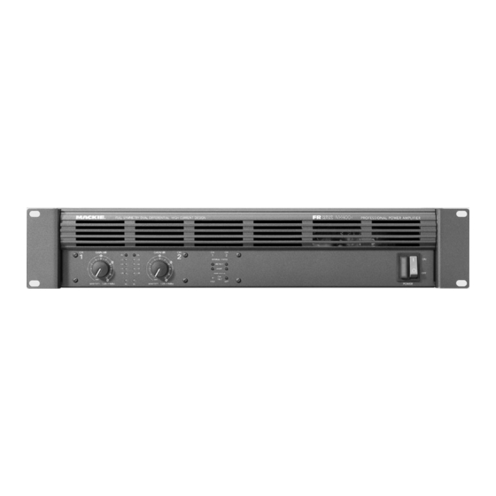
M•1200/M•1400 SERVICE MANUAL SUMMARY OF FEATURES FRONT PANEL 1. GAIN Detented gain controls adjust the level sent to each output section. The gain structure is designed so that a +4dBu (1.23V rms) input signal drives the amplifier to full rated power into 4Ω. - Page 7 VERSION 1.1 REAR PANEL 1. SPEAKER OUTPUTS ® The M•1400 has Speakon connectors where the M•1200 has ¼” speaker outputs. Both models have binding posts. For bridged mono operation, the + output comes from channel one’s positive terminal and - from channel two’s positive. 2.
-
Page 8: Specifications
M•1200/M•1400 SERVICE MANUAL SPECIFICATIONS Note: Power ratings specified CONTINUOUS AVERAGE OUTPUT 120VAC (U.S. and Canada) and 240VAC POWER, BOTH CHANNELS DRIVEN: (Export) line voltages. The M•1200/M•1400 power amplifiers draw M•1200 large amounts of current from the AC line with 225 watts per channel into 8 ohms from 20Hz to continuous sine wave testing. - Page 9 6 dB/octave high-frequency shelving filter, (shelving occurs at approximately 30kHz) Since we are always striving to make our stuff better at Mackie Designs by incorporating new and improved materials, components, and manufacturing methods, we reserve the right to change these specifications at any time without notice.
-
Page 10: Circuit Theory
“mirror image” front end circuits any distortion caused by non-linear transistor curves is effectively canceled out in the bias string, without feedback! Another design feature unique to Mackie FR Series Amplifiers is the Baker Clamp. The Baker Clamp has two functions; 1) Prevent output/driver transistors saturating, 2) Drive the LIMITER LDR. -
Page 11: Protection Circuits
VERSION 1.1 PROTECTION CIRCUITS Refer to schematics on pages 27-29. The M•1200/M•1400 has two output protection circuits in addition to the rail fuses. The first mutes the amp if the output devices are loaded beyond their safe operating area (SOA). The second is a crowbar circuit that ensures the rail fuses blow if there is DC on the output. -
Page 12: Thermal Management
M•1200/M•1400 SERVICE MANUAL THERMAL MANAGEMENT Refer to schematic on page 29. The M•1200/M•1400 T-Design Heatsink/Fan cools output devices evenly and does not collect dust on the circuitry. The fan operates at two speeds, controlled by the amplifier. An LM35DZ mounted in the center of the heatsink provides temperature information to the fan control and overtemp circuits. -
Page 13: Service Procedures
VERSION 1.1 SERVICE PROCEDURES MECHANICAL PROCEDURES The M•1200/M•1400 design allows easy removal of all components and assemblies. Disassembly and reassembly should be self evident. This manual has exploded diagrams in the parts section. Several important points concerning the assembly: • 4 of the screws that secure the top cover also hold the front extrusion (curved piece) in place. -
Page 14: Troubleshooting Tips - Output Failures
M•1200/M•1400 SERVICE MANUAL TROUBLESHOOTING TIPS - OUTPUT FAILURES After a catastrophic failure, it is likely that the four +/-80V supply fuses will be blown. Replace fuses and very slowly bring up the Variac while monitoring line consumption. It is likely that substantial line current will be pulled due to shorted output parts. At the same time, look for DC offset at the output. -
Page 15: Test And Biasing Procedure
VERSION 1.1 BIAS AND TEST PROCEDURE After the unit has been repaired, the following should be done to assure long term reliable operation. If a distortion analyzer is present, distortion specifications should be verified. 1. Adjusts bias in both channels (R1 & R51) for 8mV +/- 0.3mV at bias test points (J53 & J54) after unit has idled for a few minutes. - Page 16 M•1200/M•1400 SERVICE MANUAL (THIS PAGE UNINTENTIONALLY LEFT BLANK), THOSE RESPONSIBLE HAVE BEEN PUT TO THE SWORD SERVICE PROCEDURES...
-
Page 17: Parts
VERSION 1.1 PARTS QUICK PARTS FRONT PANEL FULL SYMMETRY DUAL DIFFERENTIAL HIGH CURRENT DESIGN PROFESSIONAL POWER AMPLIFIER GAIN /dB G AIN /dB INTERNALSTATUS PROTECT SHORT TEMP ST ATUS 1& 2 1.23v (+4dBu) POWER SENSITIVITY 1.23v (+4dBu) SENSITIVIT HANDLE ASSEMBLYS GAIN CONTROLS POWER SWITCH ALL LEDS RIGHT, 080-023-10... -
Page 18: Chassis Assembly
M•1200/M•1400 SERVICE MANUAL CHASSIS ASSEMBLY PARTS... - Page 19 VERSION 1.1 CHASSIS ASSEMBLY PARTS LIST ITEM # PART # DESCRIPTION NOTES 700-028-02 SEMS 6-32X3/8 PHP BLKZC ALL SIDE PANEL SCREWS 550-221-00 TOP COVER - M1200 700-041-04 MCH 6-32X3/8 FL 100DG BLK TOP COVER TO CHASSIS 551-029-00 EXTR SCRN DSPLY BZL-M1200 551-029-10 EXTR SCRN DSPLY BZL-M1400 700-041-04...
-
Page 20: Heatsink Assembly
M•1200/M•1400 SERVICE MANUAL HEATSINK ASSEMBLY PARTS... - Page 21 VERSION 1.1 HEATSINK ASSEMBLY PARTS LIST ITEM # PART # DESCRIPTION 551-032-00 EXTR FAB HEATSINK - M1200 410-003-00 INSL SILPAD K6 W/ADHESIVE 055-081-00 PCB ASSY MAIN - 1200 080-072-01 PCB ASSY MAIN - M1400 080-072-02 PCB ASSY MAIN - M1400i 550-255-00 PIGGYBACK CLIP 700-058-02...
-
Page 22: Complete Parts List
M•1200/M•1400 SERVICE MANUAL COMPLETE PARTS LIST 040- Cables 500- Switches 640- AC Line Cords 055- Finished PCB Assys 510- Fuses 700- Hardware 100- Pots and Resistors 550- Chassis Metal 760- Knobs/Plastic 200- Capacitors 600- Transformers 790- Misc./Packing 300- Semiconductors 601- Inductors 800- Printed Material 400- Jacks/Connectors 610- Wires and Cables... - Page 23 VERSION 1.1 PART # DESCRIPTION PART # DESCRIPTION 140-111-00 RES TF SM .1W 5% 36K OHM 300-003-00 DIO SW DL4148 100V SM 140-115-00 RES TF SM .1W 5% 51K OHM 300-007-00 DIO SW 1SS244-SUB 1SS245 140-123-00 RES TF SM .1W 5% 100K OHM 301-006-00 THY 2N6507 400V 140-124-00...
- Page 24 M•1200/M•1400 SERVICE MANUAL PART # DESCRIPTION PART # DESCRIPTION 400-172-00 TERM SOLDER-IN 18AWG 700-058-02 MCH 4-40X1/2 SKT CLRZC 400-173-00 TERM .25 QKDS PCMT STABLE 700-059-00 HEX 5/16-18X3IN GD-5 400-210-00 TERM QDISC .250 F 18-22GA 704-001-01 PEMNUT 6-32 .038 STL 400-214-00 JACK 1/4 V PCMNT 1MM WASH 704-001-02 PEMNUT 6-32 .054 STL...
-
Page 25: Schematics / Pcb Layouts
THE MIXER FIXER • MACKIE DESIGNS SERVICE THE MIXER FIXER • MACKIE DESIGNS SERVICE NEWS NEWS FR Series Fuse Upgrade Model: FR Series M1200/1400, 110V only Serial #: M1200 prior to SN# AF12626 Effective 4/28/97 M1400 prior to SN# AH12657 Problem: Original fuse (15A) rated too low. -
Page 26: Input Pcb Layout
THE MIXER FIXER • MACKIE DESIGNS SERVICE THE MIXER FIXER • MACKIE DESIGNS SERVICE NEWS NEWS FR Tywrap Mod Model: FR Series M1200/1400 Serial #: AFXXXXX to AFXXXXX Effective 5/8/97 Problem: The primary and secondary wires get pinched between the top cover and the fan shroud. -
Page 27: Display Pcb Schematic
FR series Amplifier ribbon replacement instructions (NEW! IMPROVED! July 2000) Models affected: FR series M1200, M1400, M1400i M1200: All models. M1400i: Before Serial # DA20889 and all models with “AM” prefix. M1400 and 230v versions: Before Serial # DB12700 and all models with “AH” prefix. Add this as part of your normal repair procedures. -
Page 28: Display Pcb Layout
THE MACKIE FIXER • MACKIE DESIGNS SERVICE NEWS Procedure continued. Input board work: If the two ribbon cables are soldered to the input board, follow steps 7 to 11. If not, then go to step 12. Remove the metal shield plate and insulator sheet from the back of the input board. -
Page 29: Main Pcb Schematics
M•1200/M•1400 INPUT PCB 055-079-00 REV-D... - Page 30 M•1200/M•1400 INPUT PCB 055-079-00 REV-D...
- Page 31 M•1200/M•1400 DISPLAY PCB 055-080-00 REV-A...
-
Page 32: Main Pcb Layout
M•1200/M•1400 DISPLAY PCB 055-080-00 REV-A... -
Page 33: Soft Start Pcb Schematic
M•1200/M•1400 MAIN PCB 055-081-00 REV-D... -
Page 34: Soft Start Pcb Layout
M•1200/M•1400 MAIN PCB 055-081-00 REV-D... - Page 35 M•1200/M•1400 MAIN PCB 055-081-00 REV-D...
- Page 36 M•1200/M•1400 MAIN PCB 055-081-00 REV-D...
- Page 37 M•1200/M•1400 SOFT START PCB 055-162-00 REV-A...
- Page 38 M•1200/M•1400 SOFT START PCB 055-162-00 REV-A...
Need help?
Do you have a question about the FR Series M-1400 and is the answer not in the manual?
Questions and answers