
Related Manuals for Mackie FAST RECOVERY M-1200


Summarization of Contents
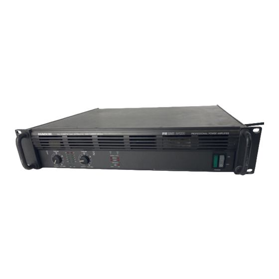
Mackie Amplifier Introduction
Service by Experienced Technicians Only
Warning that only qualified personnel should service the unit.
Surface Mount Component Usage
Highlights use of SMD components, requiring specialized repair skills.
Technical Support Information
Contact details and availability for Mackie technical support.
Document Disclaimer
States manual is proprietary and copyright protected.
Mackie FR Series System Overview
Model Differences: M1400, M1400i, M1200
Details key differences between M1400, M1400i, and M1200 amplifier models.
Fast Recovery Design Explained
Explains Mackie's patented Fast Recovery circuitry and its benefits.
Mackie FR Series Amplifier Features
Front Panel Controls and Indicators
Describes front panel gain controls, meters, and status LEDs.
Rear Panel Connectivity and Settings
Details rear panel inputs, outputs, and operational mode switches.
Mackie FR Series Technical Specifications
Power Output and Rating Notes
Lists continuous and maximum power ratings with AC line notes.
Frequency and Distortion Performance
Covers bandwidth, frequency response, and distortion metrics.
Electrical Performance Specifications
Details SNR, channel separation, input impedance, and sensitivity.
Dynamic Performance and Filtering
Covers rise time, slew rate, HF stability, and filter functions.
Mackie FR Series Circuit Theory
Input Circuitry Explained
Details the signal path from input to the main board.
Power Amplifier Circuitry
Explains Class AB output stage and unique frontend designs.
Protection Circuitry
Describes SOA and DC crowbar protection mechanisms.
Thermal Management System
Explains fan control and thermal shutdown features.
Mackie FR Series Service Procedures
Mechanical Disassembly and Reassembly
Provides guidance on physical disassembly and reassembly of the unit.
Required and Recommended Service Equipment
Lists essential tools and equipment for troubleshooting and verification.
Troubleshooting Output Failures
Offers guidance on diagnosing and resolving output stage problems.
Bias and Test Procedure
Outlines steps for setting bias and verifying performance post-repair.
Mackie FR Series Parts Identification
Quick Parts List - Front and Rear Panels
Provides a quick reference for common front and rear panel components.
Chassis Assembly Diagram and Parts List
Illustrates chassis components and lists parts for assembly.
Heatsink Assembly Diagram and Parts List
Shows heatsink components and lists parts for assembly.
Complete Parts List
An extensive list of all available replacement parts for the amplifier.
Mackie FR Series Service Bulletins
FR Series Fuse Upgrade
Details an important fuse replacement for reliability and safety.
FR Tywrap Wire Management Modification
Describes a modification to prevent wire pinching with tywraps.
Ribbon Cable Replacement Procedure
Instructions for replacing potentially defective ribbon cables.
Mackie FR Series Schematics and PCB Layouts
Input PCB Schematic and Layout
Detailed schematic and component layout for the input PCB.
Display PCB Schematic and Layout
Schematic and component layout for the display PCB.
Main PCB Schematics (Left and Right Amps)
Schematics for the main amplifier printed circuit board.
Main PCB Layout
Component layout diagram for the main printed circuit board.
Soft Start PCB Schematic and Layout
Schematic and component layout for the soft start circuit.
Need help?
Do you have a question about the FAST RECOVERY M-1200 and is the answer not in the manual?
Questions and answers